IgniteNet ICC-MMC-WW User manual

– 1 –
Quick Start Guide
1. Unpack and Check Contents
ICC-MMC-WW Media Converter
Grounding screw
2. Mount the Media Converter
a. Mounting on a Pole
Place the unit against the pole (diameter 20-200 mm).
Use up to 12 mm (1/2 in) strapping to secure the unit to the
pole.
b. Mounting on a Wall
In the required location, mark and drill three holes in the wall
for M4 wall anchors (not included).
Note:
For a wood wall, drilling holes and using wall anchors
is not required.
Mount the unit on the wall and secure it in place using three
M4 x20 tapping screws (not included).
2
1
1
2
2
1
1
2
3. Ground the Media Converter
Ensure the structure on which the unit is to be mounted is
properly grounded and in compliance with ETSI ETS 300 253.
Verify that there is a good electrical connection to a
grounding point (no paint or isolating surface treatment).
Use the included screw to attach a grounding wire (not
included) to the grounding point inside the unit, and then to
ground.
Caution:
The earth connection must not be removed
unless all supply connections have been disconnected.
4. Connect Power
The media converter can be powered by a 24 to 48 VDC passive PoE
injector or by connecting an external 24 to 48 VDC power source to
its DC terminal block.
a. PoE Power
Connect Category 5e or better cable to the PoE Out/In RJ-45
port.
Connecting Ethernet cable from an optional passive PoE
injector can power on the unit. (Does not require a DC power
connection.)
Note:
When powered by PoE, the DC terminal block
provides a DC power output. When powered by a DC power
input, the RJ-45 port functions as a PoE PSE (power source)
port.
In PoE PSE mode, the RJ-45 port pin definitions can be
modified by a switch on the panel:
◆IgniteNet: + (pins 1/2 & 4/5), - (pins 3/6 & 7/8)
◆Other: + (pins 4/5), - (pins 7/8)
In PoE input mode, the switch position has no function.
1
1
2
1
1
2-Port Media Converter
ICC-MMC-WW
www.ignitenet.com
Quick Start Guide
– 2 –
b. DC Power
Warning:
Before wiring the DC block or connecting power
to the device, ensure that power to the feed lines is turned
off at the supply circuit breaker or disconnected from the
power bus.
Connect the DC power feed wire to the DC block “+” pin.
Connect the ground/return wire to the DC block “-” pin.
5. Verify Switch Operation
Verify basic switch operation by checking the system LEDs.
When operating normally, the Power LED should be on
green, and the LAN and Fiber SFP port LEDs should be on or
blinking green.
6. Connect Fiber Cable
First install an SFP transceiver, and then connect fiber optic
cabling to the transceiver port.
The following transceivers are supported:
◆1000BASE-SX
◆1000BASE-LX
As the connection is made, check the Fiber SFP port status
LED to be sure the link is valid:
◆On Green — Port has a valid link.
◆Blinking Green — Indicates network activity.
12
1
2
1
1
2
1
1
2
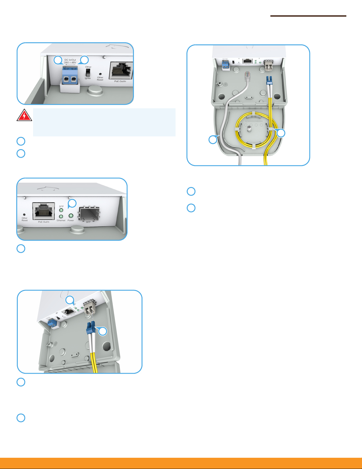
7. (Optional) Add Cable Strain-Relief Attachment
The optional attachment provides strain relief for the Ethernet,
fiber, and DC cables connected to the unit.
Route the Ethernet and DC cables through the left side of
the attachment.
Route the fiber cable through the right side of the
attachment and round the strain-relief feature at least once
before exit.
2
1
1
2

Quick Start Guide
– 3 –
Safety and Regulatory Information
FCC Class A
This equipment has been tested and found to comply with the limits for
a Class A digital device, pursuant to part 15 of the FCC Rules. These limits
are designed to provide reasonable protection against harmful
interference when the equipment is operated in a commercial
environment. This equipment generates, uses, and can radiate radio
frequency energy and, if not installed and used in accordance with the
instruction manual, may cause harmful interference to radio
communications. Operation of this equipment in a residential area is
likely to cause harmful interference in which case the user will be
required to correct the interference at his own expense.
You are cautioned that changes or modifications not expressly approved
by the party responsible for compliance could void your authority to
operate the equipment.
You may use unshielded twisted-pair (UTP) for RJ-45 connections -
Category 3 or better for 10 Mbps connections, Category 5 or better for
100 Mbps connections, Category 5, 5e, or 6 for 1000 Mbps connections.
For fiber optic connections, you may use 50/125 or 62.5/125 micron
multimode fiber or 9/125 micron single-mode fiber.
This device complies with Part 15 of the FCC Rules. Operation is subject
to the following two conditions:
(1) This device may not cause harmful interference, and
(2) this device must accept any interference received, including
interference that may cause undesired operation.
CE Mark
CE Mark Declaration of Conformance for EMI and Safety (EEC)
This information technology equipment complies with the requirements
of the Council Directive 2014/30/EC on the Approximation of the laws
of the Member States relating to Electromagnetic Compatibility and
2014/35/EC for electrical equipment used within certain voltage limits.
For the evaluation of the compliance with these Directives, the following
standards were applied:
RFI Emission:
◆Limit according to EN 55032:2012/AC:2013, Class A
◆Limit for harmonic current emission according to EN 61000-3-
2:2014, Class A
◆Limitation of voltage fluctuation and flicker in low-voltage supply
systems according to EN 61000-3-3:2013
Immunity:
◆
Product family standard according to EN 55024:2010, Class A
◆Electrostatic Discharge according to IEC 61000-4-2:2008 ED. 2.0
◆Radio-frequency electromagnetic field according to IEC 61000-4-
3:2010 ED. 3.2
◆Electrical fast transient/burst according to IEC 61000-4-4:2012
ED. 3.0
◆Surge immunity test according to IEC 61000-4-5:2014 ED. 3.0
◆Immunity to conducted disturbances, Induced by radio-frequency
fields: IEC 61000-4-6:2013 ED. 4.0
◆Power frequency magnetic field immunity test according to IEC
61000-4-8:2009 ED. 2.0
◆Voltage dips, short interruptions and voltage variations immunity
test according to IEC 61000-4-11:2004 ED. 2.0
LVD:
◆EN 60950-1:2006+A1:2010+A11:2009+A12:2011+A2:2013
The Declaration of Conformity (DoC) can be obtained from
www.ignitenet.com/support.
Laser Safety
Warning: Fiber Optic Port Safety:
Avertissment: Ports pour fibres optiques - sécurité sur le plan optique:
Warnhinweis: Faseroptikanschlüsse - Optische Sicherheit:
Warnings and Cautionary Messages
When using a fiber optic port, never look at the
transmit laser while it is powered on. Also, never look
directly at the fiber TX port and fiber cable ends when
they are powered on.
Ne regardez jamais le laser tant qu'il est sous tension.
Ne regardez jamais directement le port TX
(Transmission) à fibres optiques et les embouts de
câbles à fibres optiques tant qu'ils sont sous tension.
Niemals ein Übertragungslaser betrachten, während
dieses eingeschaltet ist. Niemals direkt auf den Faser-
TX-Anschluß und auf die Faserkabelenden schauen,
während diese eingeschaltet sind.
Warning:
This product does not contain any serviceable user
parts.
Warning:
Installation and removal of the unit must be carried
out by qualified personnel only.
Warning:
This product uses lasers to transmit signals over
fiber optic cable. The lasers are compliant with the
requirements of a Class 1 Laser Product and are inherently eye
safe in normal operation. However, you should never look
directly at a transmit port when it is powered on.
Warning:
When selecting a fiber SFP device, considering
safety, please make sure that it can function at a temperature
that is not less than the recommended maximum operational
temperature of the product. You must also use an approved
Laser Class 1 SFP transceiver.
Caution:
Wear an anti-static wrist strap or take other suitable
measures to prevent electrostatic discharge when handling this
equipment.
Caution:
Do not plug a phone jack connector in the RJ-45
port. This may damage this device.
Caution:
Use only twisted-pair cables with RJ-45 connectors
that conform to FCC standards.
CLASS 1
LASER DEVICE
DISPOSITIF LASER
DE CLASSE 1
LASERGER TÄ
DER KLASSE 1

Quick Start Guide
– 4 –
Hardware Specifications
Chassis
Size (WxDxH) 119 x 182.8 x 30 mm (4.69 x 7.2 x 1.18 in)
Weight 425 g (0.94 lb)
Temperature Operating: -20° C to 65° C (-4° F to 149° F)
Storage: -40° C to 70° C (-40° F to 158° F)
Humidity Operating: 5% to 90% (non-condensing)
Network Ports ◆One 1000BASE-T RJ-45 PoE port
◆One 1000BASE SFP port
Waterproof/
Dustproof IP55
Status LEDs Power, Ethernet, SFP
Power
DC Input Power 24 – 48 VDC, 1.0 A
PoE Input Power 24 – 48 VDC, 1.0 A
PoE Output Budget 20 W
Power Consumption 4 W maximum
Standards
Ethernet IEEE 802.3z 1000BASE-SX/LX
IEEE 802.3ab 1000BASE-T
Regulatory Compliance
Emissions EN 55032:2012/AC:2013, Class A
EN 61000-3-2:2014, Class A
EN 61000-3-3:2013
FCC Class A
Immunity EN 55024:2010
IEC 61000-4-2/3/4/5/6/8/11
E102016-CS-R02
150200001269X
Other IgniteNet Media Converter manuals

Popular Media Converter manuals by other brands


MuxLab
MuxLab 500701 Quick installation guide

GrandTec
GrandTec PC to Video Component GXP-2000 Specifications

Technica
Technica 100BASE-T1 MediaConverter NXP manual

Meanwell
Meanwell DDRH-120-12 Installation

Black Box
Black Box AC311A manual

Baumer Hübner
Baumer Hübner POG 10 Mounting and operating instructions


