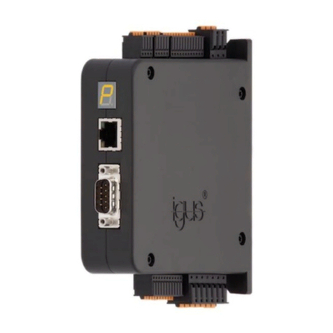
igus drylin dryve D3 User manual

Operating Instructions of the dryve D3 V0.0 1/15
dryve D3 DC motor control system
Manual V 0.0
Motion Plastics

Table of contents
Operating Instructions of the dryve D3 V0.0 2/15
Table of contents
1
Safety instructions, protective measures and guidelines............................ 3
1.1
Important instructions........................................................................ 3
1.2
Qualified personnel........................................................................... 3
1.3
Maintenance...................................................................................... 3
1.4
Safety instructions............................................................................. 4
1.4.1
Classification of information .............................................................. 4
1.5
Electromagnetic compatibility (EMC)................................................. 4
1.6
EC Declaration of Conformity............................................................ 4
2
Product overview ............................................................................................. 5
2.1
Technical data................................................................................... 5
2.1.1
Dimensions ....................................................................................... 5
2.1.2
Mechanical data................................................................................ 5
2.1.3
Electrical data.................................................................................... 5
2.1.4
Environmental conditions.................................................................. 5
3
Installation........................................................................................................ 6
3.1
Mechanical installation...................................................................... 6
3.2
Electrical installation.......................................................................... 6
3.2.1
General information about the electrical installation.......................... 7
3.2.2
Terminal assignment......................................................................... 7
4
Initial operation ................................................................................................ 8
4.1
Control elements............................................................................... 8
4.2
Motor rotation direction...................................................................... 9
4.3
Limit switch........................................................................................ 9
4.4
External directional switch................................................................10
4.5
Basic settings...................................................................................10
4.5.1
Operating modes..............................................................................10
4.5.2
Limit switch control...........................................................................11
4.5.3
Acceleration type and ramps............................................................11
4.5.4
Motor settings...................................................................................13
4.5.5
Table Basic Settings.........................................................................13
4.5.6
Speed...............................................................................................14
4.5.7
Force setting ....................................................................................14
5
Troubleshooting..............................................................................................15
6
Accessories.....................................................................................................15
7
Service .............................................................................................................15

Safety instructions, protective measures and guidelines
Operating Instructions of the dryve D3 V0.0 3/15
1 Safety instructions, protective measures and guidelines
1.1 Important instructions
Read this manual carefully before operating the dryve D3 motor control system. Familiarise yourself with the safety instructions
and ensure that the required safety measures are followed.
This manual was created according to the best of our knowledge and belief. It is used for technical documentation and for as-
sisting the user during the initial operation. The warnings, cautions and instructions issued by igus regarding the dryve D3 motor
control system must in any case be passed on to the end user if the dryve D3 motor control system is used as part of an overall
system.
The company igus undertakes guarantees only for igus products in accordance with the standards, norms and specifications
given in this manual. The guarantee covers only the replacement or repair of a defective dryve D3 motor control system. There
is no liability for consequential damage and consequential errors. The igus GmbH does not take any responsibility for the inte-
gration of the dryve D3 motor control system into the overall system. The responsibility for it lies with the plant designer or the
end user. Please observe the instructions under "Qualified Personnel". The company igus assumes no responsibility for per-
sonal injury or damage to property resulting from misuse or unauthorised technical modification of the dryve D3 motor control
system.
The igus GmbH reserves the right to make changes and improvements to the product or the technical documentation
at any time without prior notice.
The dryve D3 motor control system must only be used if:
- All information and safety instructions in this manual have been observed.
- No changes have been made to the dryve D3 motor control system and it is in a technically
flawless condition.
- The operating limits that are specified in Technical data are complied with.
- Necessary measures, if called for, have been taken for radio interference suppression depending on the operating
environment.
- All used connecting cables have been relieved of strain.
1.2 Qualified personnel
The operation of the product must only be carried out by qualified personnel.
Personnel must:
- Have read and understood this manual and documentation on the installed motor, axis and accessories.
- Be familiar with all relevant applicable standards, provisions and accident prevention regulations.
- Be able, due to their training, to anticipate or recognise any hazards that may arise when using the control system.
- Ensure the safety of persons and objects when using the motor control system in the overall
system.
1.3 Maintenance
The dryve D3 motor control system is maintenance-free.
Never open the housing of the dryve D3 motor control system independently, even in the event of a malfunction.
Opening the housing annuls the guarantee.

Safety instructions, protective measures and guidelines
Operating Instructions of the dryve D3 V0.0 4/15
1.4 Safety instructions
1.4.1 Classification of information
The degree and type of hazard are assigned to one of the following classes.
DANGER
!
Safety instructions marked with DANGER indicate an imminently hazardous situation.
A disregard of the notice
inevitably
leads to a
serious or even fatal accident
.
WARNING
!
Safety instructions marked with WARNING indicate a potential hazardous situation.
Failure to observe this notice is
likely
to result in a
serious or fatal accident
or
property damage
.
CAUTION
!
Safety instructions marked with CAUTION indicate potential danger.
Failure to comply with the notice may
possibly
result in an
accident
or
property damage
.
NOTE
Safety instructions marked with NOTE indicate a potential hazardous situation.
Disregard of the notice may
possibly
result in
property damage
.
1.5 Electromagnetic compatibility (EMC)
WARNING!
•Risk of injury due to interference with signals and devices
Disturbed signals can cause unforeseen device reactions.
Carry out the wiring in accordance with the EMC measures.
Failure to
follow these instructions can result in death, serious injury, or material damage
Measures for EMC Effect
Device assembly Use cable clamps for the shield support, con-
nect metal parts over a large area. Good conductivity due to surface contact.
Switching devices such as contactors, relays or
solenoid valves with interference suppression
units or spark suppressors (e.g. diodes, varis-
tors, RC elements)
Reduce mutual interference couplings.
Wiring Keep cables as short as possible. Avoid capacitive and inductive interference.
Connect the shield of all shielded cables to the
housing via cable clamps over a large
area.
Reduce emissions.
1.6 EC Declaration of Conformity
Hereby the igus GmbH declares
that the following device
dryve D3 DC motor control system
complies with the relevant provisions of the following directives:
EMC guideline 2014/30/EU
RoHS -2 guideline 2011/65/EU
Applied harmonized standards:
EN 61000-6-2 : 2005
EN 61000-6-3 : 2007 + A1: 2011
Cologne, March 2018

Product overview
Operating Instructions of the dryve D3 V0.0 5/15
2 Product overview
Ready to use immediately
Connect the voltage source and the motor: you are ready to start. No complicated software installation or complex wiring of vari-
ous additional switches and sensors.
Easy control
The intuitively operated rotary elements allow you to set the speed and force limit of the connected motor without prior
knowledge. A travel movement can be started by the two buttons on the front of the dryve D3.
2.1 Technical data
2.1.1 Dimensions
The shading indicates the distance for neighbouring components.
2.1.2 Mechanical data
D x W x H dryve D3 in mm
116 x 27 x 126
Weight
150 g
D x W x H angle adapter in mm
Weight
2.1.3 Electrical data
Voltage supply 24 V, ± 2 V
Motor types DC motor
Continuous motor current Max. 2.5 A
Motor output frequency Switch 4 off 8 kHz
Switch 4 on 1 KHz
Power output Max. 60 W
Cable lengths Max.3 m
Cable cross-sections 0.34 mm² to 1.5 mm²
Limit switch Voltage U
B
at X2.1
Current
Max. 10 mA
External travel movement Voltage 5 V
Current
5mA
2.1.4 Environmental conditions
Ambient temperature Operation -20 °C to +45 °C
Transport -40 °C to +60 °C
Bearing -40 °C to +60 °C
Relative humidity ≤90 %, non-condensating
Protection class IP 30
Degree of soiling according to EN 61010 1

Installation
Operating Instructions of the dryve D3 V0.0 6/15
3 Installation
3.1 Mechanical installation
WARNING!
•Danger of malfunction
•Fire hazard
•Explosion hazard
Never operate the dryve D3 motor control system in water or in an aggressive, flammable or explosive atmosphere. Always
pay attention to the
Environmental conditions
- Installation in a switch cabinet can be done on a TS 35 support rail (EN 50022) by mounting on the separately available
angle adapter.
- The installation site must be free of extreme vibrations or shocks.
- The dimensions for adjacent components can be found in the drawing at Dimensions
- The heated air flow of other devices and components must not be led through the area of the dryve D3.
- MTTF VALUE
3.2 Electrical installation
WARNING!
•Risk of injury
Make sure that an emergency shutdown can be
performed at all times.
CAUTION!
•Danger of electrical voltage
•Danger of electric arcs
Always turn off the power before disconnecting or making electrical connections in the system. Secure the power supply
against restart.
After switching off, wait at least 5 minutes until further work is carried out.
Check the absence of voltage before working on the system.
Danger of improperly mounted electrical connections.
Do not allow cables to be unmounted and ensure that all connections are secure.
CAUTION!
•Electromagnetic alternating fields
Electromagnetic fields around the live wires may cause interference. Lay the supply and motor cables separately from the
control cables. Use the shortest possible cable lengths. Follow the instructions for Electromagnetic compatibility
NOTE
An operating voltage above the voltage specified in the technical data, as well as the swapping of the connections will de-
stroy the dryve D3 motor control. system.
Select an operating voltage within the voltage range specified in the technical data.

Installation
Operating Instructions of the dryve D3 V0.0 7/15
3.2.1 General information about the electrical installation
The dryve D3 was designed for connection to DC voltages.
All voltage specifications listed in this operating manual should therefore be regarded as DC voltage.
WARNING!
•Danger from sudden movements
To ensure that the dryve D3 can be operated without interference, the voltage supply must not be executed as PELV (func-
tional extra-low voltage with safe insulation: Protection by extra low voltage, active conductor connected to ground or protec-
tive conductor). This can lead to unpredictable malfunctions of the D3 dryve.
3.2.2 Terminal assignment
Interconnect the connectors according to your application. Use the detailed illustrations for the individual terminals in the follow-
ing.
The terminals are connected as follows:
1. Insulate the cores over a length of 8 mm
2. Press the white spring of the core opening by hand
or with a screwdriver into the terminal block.
3. Push the core deep into the opening.
4. Remove the white spring out of the
connector again.
QR code video description

Initial operation
Operating Instructions of the dryve D3 V0.0 8/15
4 Initial operation
The following describes the initial operation, which makes the start easy.
You can find informative videos on the initial operation at igus.eu/D3
Interconnect the whole system according to EMC guideline
Minimum equipment
To control a motor with the D3 dryve, a minimum equipment has to be provided by the user:
1. Voltage source with 24 V and connecting cables
2. Motor with suitable cable
WARNING
!
•Fire hazard
Faulty settings of the dryve D3 motor control system can lead to extremely high motor temperatures.
NOTE
A faulty connection can
damage or destroy the dryve D3 or drive.
QR code video?
4.1 Control elements
DANGER
!
•Danger of falling load
Never work under unsecured vertical axes and loads.
Secure
the axis or load against falling by a mechanical safety device or other approved safety method.

Initial operation
Operating Instructions of the dryve D3 V0.0 9/15
4.2 Motor rotation direction
For proper operation, it is necessary that the motor rotates in a defined direction.
For determination, please use the following procedure:
1. View from the motor shaft to the motor
2. Actuation of the button S2 for clockwise rotation
3. Clockwise direction of rotation of the motor corresponds to a right-hand rotation
If the motor rotates counterclockwise, the polarity of the motor connecting cables must be changed.
4.3 Limit switch
Two different types of limit switches can be connected to the dryve D3.
•Passive mechanical switches with NC functionality (NC - Normally Closed)
•Active electronic proximity switches with NC functionality in PNP interconnection (NC - Normally Closed)
Connected limit switches are supplied via the supply voltage (X2.1) connected to the dryve D3
For both types, different connection options must be taken into account.
Mechanical switches
The switches are connected to a voltage output and the respective signal input.
The right limit switch is connected to X3.1 and X3.2, the left to X3.4 and X3.5.
Electronic switches
The switches must be connected to a voltage output, the signal input and 0 V respectively.
The supply voltage of the right limit switch is connected to X3.1, the output signal to X3.2 and 0 V to X3.3. The supply voltage of
the left limit switch is connected to X3.4, the output signal to X3.5 and 0 V to X3.6.
In order to guarantee a logical and safe function, the limit switches must be assigned correctly to the respective running direc-
tion. A functionally connected, non-activated limit switch is indicated by a green LED below the respective direction button.
If a limit switch becomes active, the LED 1 below the respective direction button goes out. Please check that the LED 1 below
the left S1 button at the left limit switch also turns off. A test can also be carried out without driving the motor. If the connected
logic is not correct, the positions of the limit switches must be interchanged.

Initial operation
Operating Instructions of the dryve D3 V0.0 10/15
4.4 External directional switch
Travel movements can be remotely controlled via an external wiring.
For this purpose, normally-open (NO) passive switching contacts are connected to X4.1 and X4.2 as well as X4.3 and X4.4.
These switching contacts can be push buttons, relays and also optocouplers. A higher-level control system can be used via po-
tential-free contacts. The function is identical to the function of the buttons S1 and S2.
If a button combination for left-hand/right-hand rotation with only 3 connecting cables is used, then X4.2 and X4.4 must be
bridged. The common cable of the button combination must be connected to these bridged connections.
The buttons for left and right are connected to X4.1 and X4.3 respectively
NOTE
No
external potential must be connected to X4 as this may destroy the dryve D3.
4.5 Basic settings
In its delivery condition, all switches are set to "off" (down position).
4.5.1 Operating modes
Tip mode
The motor is moved to the left or right when button S1 or S2 is pressed. If the button is not pressed, the motor stops.
Start to end mode
The motor is moved to the left or right after pressing button S1 or S2.
The motor stops only when:
1. One of the two buttons is pressed
2. The movement encounters a block whose resistance is greater than the Force which the motor is allowed.
3. The Limit switch is triggered at the end of the movement.

Initial operation
Operating Instructions of the dryve D3 V0.0 11/15
4.5.2 Limit switch control
Limit switch
A travel movement is automatically stopped if:
1. The limit switch is triggered in the direction in which the movement is executed.
2. The movement encounters a block whose resistance is greater than the Force which the motor is allowed.
Block travel
A travel movement is automatically stopped if:
1. The movement encounters a block whose resistance is greater than the Force which the motor is allowed.
NOTE
This operating mode is only suitable for drives/motors which, due to their own torque, cannot damage the mechanical struc-
ture of the axis! With strong drives with incorrectly adjusted force limitation, the mechanical structure can be damaged or
destroyed! The suitability can be resolved by checking the motor data sheet and the axis parameters.
In this mode, the motor travels until the set force is reached (P1 force limit) and then shuts off.
For this reason, it is important that the Force limitation is set correctly.
4.5.3 Acceleration type and ramps
The maximum achievable acceleration depends on the connected motor, a possibly existing gearbox and the connected linear
or rotary axis as well as the load to be moved.
Basically, the deceleration cannot be influenced by the settings of the dryve D3. This is determined by the mechanical proper-
ties of the combination of the motor, a possibly existing gearbox and the connected linear or rotary axis and the load to be
moved.
Maximum acceleration
The motor is maximally accelerated to the pre-set speed.
Acceleration ramps
The motor is accelerated according to the selected ramp.
It is possible to set 5 different accelerations.
In the delivery state, the acceleration ramp 3 is set.

Initial operation
Operating Instructions of the dryve D3 V0.0 12/15
Setting the acceleration:
1. Activation of the acceleration change mode by simultaneously pressing buttons S1 and S2 for at least 5 seconds
(LED 7 lights up red) -> LEDs 4 to 7 flash 5 times.
2. Release both buttons
3. LED 7 flashes at intervals -> number of flashes represents the set acceleration
4. Change the acceleration by pressing button S1 until LED 4 "Motor running" lights up
5. Release the button S1 -> The next acceleration is set and LED 7 flashes repeatedly corresponding to the selected
acceleration number
6. After acceleration 5, acceleration 1 follows again
7. To exit the acceleration change mode, press the S2 button for at least 3
seconds -> the LEDs 4 to 7 flash 5 times
For initial operation videos, see igus.eu/D3

Initial operation
Operating Instructions of the dryve D3 V0.0 13/15
4.5.4 Motor settings
DC motors with low inductances
If the operating mode for highly inductive motors is used with this type of motor, it can lead to an increased noise level as well
as not reaching the maximum speed.
DC motors with high inductances
If the operating mode for low inductive motors is used with this type of motor, it can lead to an increased noise level as well as
not reaching the maximum speed.
4.5.5 Table Basic Settings
Dip switch
Function
Operating
modes
Tip mode
Start to end mode
Limit switch
control
Limit switch
Block travel
Acceleration
Maximum acceleration
Acceleration
Motor
settings
Low inductances
High inductances

Initial operation
Operating Instructions of the dryve D3 V0.0 14/15
4.5.6 Speed
The speed can be adjusted continuously from 0% to 100% of the motor speed via the potentiometer P2. At 50% of the achieva-
ble speed, a lock is available for more precise setting.
The maximum achievable speed depends on the connected motor, a possibly existing gearbox and the connected linear or ro-
tary axis as well as the load to be moved.
4.5.7 Force setting
The maximum force of the drive, i.e. the maximum current output, should always be set correctly to suit the respective mechani-
cal structure. This also applies to the use in limit switch operation.
To determine and test the ideal setting for the limitation, select the operating mode Tip mode and the maximum.Acceleration.
Setting the optimal force limit:
1. Turn the potentiometer for force limit P1 and the setpoint speed P2 clockwise to the end stop.
2. Move the connected motor incl. load in a free direction.
3. Reduction of the permissible force by a counterclockwise rotation of the potentiometer P1
4. Restart the drive. The current limit LED 5 (yellow) becomes active and after approx. 3 - 5 seconds the dryve D3 exe-
cutes an overcurrent switch-off. This is manifested by a motor stop and a glowing of the LED 6 (red).
5. Increase the force limitation in small steps by turning the potentiometer P1 clockwise
6. Renewed drive of the motor
7. Complete the settings
a. The LED 5 (yellow) goes out after a maximum of 1 second -> correct adjustment of the force limitation
b. The LED 5 (yellow) remains active for more than 1 second and possibly a motor stop is executed -> re-
newed increase in the force limit

Service
Operating Instructions of the dryve D3 V0.0 15/15
5 Troubleshooting
Problem
Description
Remedy
The motor control system does not
carry out any more travel movements When the buttons S1 and S2 are actu-
ated, a colour change of the LED 3
from green (function OK) to red (defect)
is
to be observed
Please contact Customer service
6 Accessories
AK-DCCON-D3-0001 Top-hat rail mounting adapter kit
7 Service
Customer service
+49 (0) 2203-9649-845
Technical support for igus dryve motor control systems
Website dryve
http://www.igus.eu/D3
Download the dryve D3 firmware, manual and specifications
Ordering of further motor control systems
Website drylin E
www.igus.eu/drylinE
Download data sheets of the electric drive technology
Ordering of motors, limit switches and other accessories
Website drylin drive technology
www.igus.eu/drivetechnology
Download data sheets of the mechanical drive technology
Ordering of axes, linear robots and accessories
Contact
www.igus.eu
+49 (0) 2203-9649-0
Imprint
All rights reserved:
igus GmbH
Spicher Str. 1a
51147 Cologne, Germany
© 2018
Table of contents
Other igus Control System manuals
Popular Control System manuals by other brands
Siemens
Siemens SIMATIC BATCH operating manual
MANU ELECTRONICS
MANU ELECTRONICS ManuFlo ME3000-RPFS Information sheet
David Clark
David Clark u3800 Installation & operation instructions
WAREMA
WAREMA Wisotronic operating instructions
Distech Controls
Distech Controls EC-BOS-6AX Mounting and wiring instructions
Carrier
Carrier 3V VVT 33ZCVVTZC-01 Installation and start-up instructions
