Frico PLS Competent User manual

PLS Competent
Quick guide
PLSAC
GB

2
PLS Competent
Wiring diagram - units with water heat
PLSAC 2
PLSB1/B2
7 8 910 11 12 15 16 17 18 19 20
COM 1 COM 2 ROOM
C2
X5
C1
X4
ROOM
X3
Pot.
Unit ID ACTUATORSUPPLY
N L NL
PE
L
~
230V~
C2
X5
C1
X4
ROOM
X3
Pot.
Unit ID ACTUATORSUPPLY
N L NL
PE
L
~
230V~
C2
X5
C1
X4
ROOM
X3
Pot.
Unit ID ACTUATORSUPPLY
N L NL
PE
L
~
230V~
+-
CNC
SIReDC
SIReRTX
(optional)
SIReC1X
SIReCC6XX (max 10 m)
SIReB1/B2/B1EC
SIReB1/B2/B1EC
SIReB1/B2/B1EC
SIReCC6XX
(max 50 m)
SIReCC6XX
(max 50 m)
SIReCC6XX
(max 50 m)
SIReCC4XX
(max 20 m)
BUS
SD230
SD230
SD230
L=1,5m
L=2m
SIReUA1 SIReC1X
PLSB1/B2
PLSRTX
(optional)
CC6XX
CC6XX (max 10 m)
PLSUA1
PLSB1/B2
PLSB1/B2
CC6XX
PLSC1X
CC6XX CC4XX
PLSC1X
DC

3
PLS Competent
3 1
Wiring diagram - units without heat and units with electrical heat
PLSAC
7 8 910 11 12 15 16 17 18 19 20
COM 1 COM 2 ROOM
C2
X5
C1
X4
ROOM
X3
Pot.
Unit ID ACTUATORSUPPLY
N L NL
PE
L
~
230V~
C2
X5
C1
X4
ROOM
X3
Pot.
Unit ID ACTUATORSUPPLY
N L NL
PE
L
~
230V~
C2
X5
C1
X4
ROOM
X3
Pot.
Unit ID ACTUATORSUPPLY
N L NL
PE
L
~
230V~
+-
CNC
SIReUA1 SIReC1X
SIReDC
SIReRTX
(optional)
SIReC1X
SIReCC6XX (max 10 m)
SIReB1/B2/B1EC
SIReB1/B2/B1EC
SIReB1/B2/B1EC
SIReCC6XX
(max 50 m)
SIReCC6XX
(max 50 m)
SIReCC6XX
(max 50 m)
SIReCC4XX
(max 20 m)
BUS
L=2m
PLSB1/B2
PLSB1/B2
PLSRTX
(optional)
CC6XX
CC6XX (max 10 m)
PLSUA1
PLSB1/B2
PLSB1/B2
CC6XX
PLSC1X
CC6XX CC4XX
PLSC1X
DC

4
PLS Competent
1
SE
GB
Wiring diagram - Advanced
SIRe B1/B2/B1EC
2
PLSB1/B2

5
PLS Competent
!
=
=
OK OK
4
3a
Wiring diagram - Advanced
8
7
0
1
2
3456
9
!
3b
=
1
0
OK

6
PLS Competent
5
?
Svenska Polski
Norsk Русский
English English
Deutsch Čeština
Français Slovenčina
Italiano Türkçe
Español Deutsch
Nederlands Română
Suomi Magyar
Dansk Українська
UA1Y UA1Z

7
PLS Competent
Quick guide/Start up
1. Check that all constituent parts are
present (see section Constituent parts).
2. Mount and connect all units and
components and where applicable
accessories (e.g. actuator), see wiring
diagram. When several units are connected
set a unique ID for each unit (1-9) which is
set in the ID selector of the PLSB1/B2.
Each unit should have a unique ID on its
PLSB1/B2 card.
3. Power up all units.
4. The start-up wizard runs and basic settings
are made. The system check identifies
connected components in the system and
the function test shows if all units are
correctly connected.
To run the unit
temporarily without
external control
select mode 0.
0
1
2
3
45
6
7
8
9
Operation without control unit
0
1
2
345 6
7
8
9
X5
C2
X4
C1
X3
ROOM
PE N L
SUPPLY 230V
ACTUATOR
230V

8
PLS Competent
Constituent parts
PLSAC
Option
Type Description HxWxD
[mm]
L
[m]
PLSUA1 Control unit, with internal room sensor, wall unit cover 120x70x35
PLSC1X PC Board HUB Competent 202x139x50
DC Magnetic door contact
CC603 Modular cable RJ12 (6/6) 3
CC605 Modular cable RJ12 (6/6) 5
PLSUA1 CC
PLSRTX CJ4 CJ6 CC
Type Description HxWxD L
[m]
PLSRTX External room temperature sensor 70x33x23 10
CJ4 Joint piece for two pcs. RJ11 (4/4)
CJ6 Joint piece for two pcs. RJ12 (6/6)
CC603 Modular cable RJ12 (6/6) 3
CC605 Modular cable RJ12 (6/6) 5
CC610 Modular cable RJ12 (6/6) 10
CC615 Modular cable RJ12 (6/6) 15
CC640 Modular cable RJ12 (6/6) 40
CC403 Modular cable RJ11 (4/4) 3
CC405 Modular cable RJ11 (4/4) 5
CC410 Modular cable RJ11 (4/4) 10
CC415 Modular cable RJ11 (4/4) 15
PLSC1X DC

9
PLS Competent
Water control - valve kit
*) See separate manual.
Water control - valve system*
Type Description Connection
VKF15LF TAC15LF + AV15 DN15
VKF15NF TAC15NF + AV15 DN15
VKF20 TAC20 + AV20 DN20
VKF25 TAC25 + AV25 DN25
VKF32 TAC32 + AV32 DN32
SD230 Actuator on/off 230V
BPV10 By-pass valve DN10
VOT15 Three way valve and actuator on/off DN15
VOT20 Three way valve and actuator on/off DN20
VOT25 Three way valve and actuator on/off DN25
SD230
TAC
AV
BPV10
SD230BPV10
AVTAC
VKF
VLSP
SD230
TRVS
SD230TRVS
VOT

10
PLS Competent
OFF
Fan speed step
Back Forward/ Confirm
Alarm Red led
Run signal Green led
Heating step
Week program
Day
Week program
Night
Week program
Out of operation
Overview
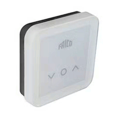
Control unit PLSUA1
Air curtains
19
IN
.0
°C
DOOR
CL

11
PLS Competent
Service menu
The service menu is password protected
and is used for support in contact with an
authorised installer.
General settings
Language, time, date, function test, manual
system check and factory reset.
Alarm and error codes
Current settings
Current set values.
Temperature settings
Day/night temperature. The night
temperature is only valid when the week
program is activated.
System on/off
Safety features are still active when the
system is switched off.
Installer menu
Password 1932
Installer status screen
Current settings and functions.
Week program
Activate week program, check, change, add or
erase program.
Fan settings
Fan control and over run functions.
Main menu
Reset alarm
Note! Before resetting, check that the fault is
rectified and there is nothing to prevent the
unit from being recommissioned.
Press and select reset alarm.
At the first start up alarm and error codes
can occur, these will usually be reset without
actions.
Power failure
Note! A power loss longer than 7 days may
require an adjustment of time and date.
The week program is affected if the clock is
not correctly set.
Fan control
Maximum fan speed and fan speed when the
door is closed. Fan speed when the door is
closed is only valid when using PLSAC.
Filter guard settings
Activate filter timer and set service interval.
External control (BMS)
External on/off, fan control 0-10V. See
"Connecting external control".
Heating settings
Set point difference open door, (calibrating
sensors).
Summer/Winter
Summer - heat off

12
PLS Competent
Table - Alarms
A1
A2
A3
A4
A5
Motor
alarm
Over
heating
alarm Check function of the contactors (E), Check function
of actuator and valve, flow temperature and bypass
settings (W).
Check internal temperature sensor,
measure resistance, 47kOhm at 25°C.
Frost
protection
alarm
The temperature in the unit
has fallen below the alarm
limit for frost protection
(only water heated units
with internal temperature
sensor).
Check the function of the actuator, valve
and bypass settings.
Check the temperature and flow of the hot water
supply.
In event of an alarm there is a risk that the coil is
damaged, check carefully for leakage and replace
the water heating coil if damaged.
Filter alarm Replace or clean the filter, if neccessary adjust the
fixed time based on how dirty the filter was and
reset the alarm.
Fixed run time before filter
alarm has been reached.
External alarm input
(terminal 9-10) on PLSC1X
has been activated
External
alarm
Check that nothing is obstructing the unit's air
intake and exhaust.
Check that nothing is obstructing the unit's air
intake and exhaust.
Check the external alarm.
Thermal contact has
deployed. One or more
motors are overheated.
When the overheated motor has cooled the
thermal switch shuts again and the alarm can
be reset. At repeated alarms, check the motors,
replace damaged motors.
Missing link on motor
protection on PLSB1/B2.
For units having built-in thermal protection but
without external connection, the motor protection
terminals must be linked.
Check motor and transformer connection
terminal on thePLSB1/B2-pc board.
The temperature in the unit
has exceeded the alarm
limit for overheating.
(Only units with internal
temperature sensor)
Unit only starts on high
speed.
For units having built-in thermal protection
but without external connection, the motor
protection terminals must be linked.
Cause ActionError code
Unit won't start.

13
PLS Competent
E1
E2
E3
E4
Communication
error
ID is set to 0 (Unit is running
continously).
Cables are not original.
Set an ID, run a Manual system check.
Make sure communication cables are correct
(the original cables has a circuit diagram
indicating how the contacts shall be crimped on
to the cable.)
In multiple unit system, check that you have
230VAC to all units.
In Installer menu - Installer status screen, check
that all units ID are listed and that no extra units
are listed. When all units are powered up run a
Manual system check.
Disconnect power, set ID=0 and reconnect
power to test the B1/B2 pc-board.
Hardware failure - replace the PLSB1/B2 pc-
board. Contact technical support.
Visual damage to PLSB1/B2.
Two or more PLSB1/B2 have
the same ID.
Try to reset the alarm. Make sure all units have
different ID-settings and perform a Manual
system check.
Program
error (No
program)
Try to reset the alarm. Disconnect power, set
ID=0 and reconnect power to test the B1/B2
pc-board - result? If the unit is running act as
if it was an E1 Communication error. If it is not
running, contact technical support.
Room sensor
error
Try to reset the alarm. Check connections and
cable. False errors can occur in conjunction
with communication error, check that all other
alarms have been reset. Measure resistance,
47kOhm at 25°C.
If the sensor intentionally has been removed,
run a Manual system check to exclude it from
the system.
PLSB1/B2 (internal pc-board)
do not communicate.
The unit won't start.
Perform a factory reset and reboot the system
(disconnect/ reconnect power).
One or more PLSB1/B2 do
not have program.
ID Error
Fault on or missing
external room sensor
PLSRTX connected to
PLSB1/B2.
Table - Error codes
Try to reset the alarm. Check connections,
modular cables and terminals, between all units
and components. Systematically shift position
of communication cables to identify a broken
terminal or cables.
Cause ActionError code

14
PLS Competent
E8
E10
E12
E20
E21
E22
E23
Fault on or missing internal
temperature sensor,PLSIT,
connected to PLSB1/B2.
Program error
(different
programs)
Two or more PLSB1/B2 in
the system have different
programs.
Fault on or missing external
room sensor, PLSRTX
connected to PLSC1X.
PLSC1X (external
pc-board) do not
communicate.
Try to reset the alarm. Check connections,
modular cables and terminals, between all units
and components. Systematically shift position
of communication cables to identify a broken
terminal or cables.
Fault on internal room
temperature sensor in
PLSUA1.
Try to reset the alarm. Check connections and
cable. False errors can occur in conjunction
with communication error, check that all other
alarms have been reset. If the error is not rectified
PLSUA1 must be replaced.
Multiple control
units connected
Try to reset the alarm.The system will only
support one control unit, disconnect and reset
alarm.
Firmware error Components of different
releases are used in the
system.
Make sure all units are from the same release,
contact technical support.
Internal sensor
Error
Room sensor
error
Room sensor
error
Communication
error
Cables are not original.
Logging tool or an extra
control unit PLSUA1 is
connected to the system.
Make sure communication cables are correct (the
original cables has a circuit diagram indicating
how the contacts shall be crimped on to the cable.)
Try to reset the alarm. Check connections and
cable. False errors can occur in conjunction with
communication error, check that all other alarms
have been reset. Measure resistance, 47kOhm at
25°C.
Try to reset the alarm. Check connections and
cable. False errors can occur in conjunction with
communication error, check that all other alarms
have been reset. Measure resistance, 47kOhm at
25°C.
Try to reset the alarm. PLS can control different
types of units, e.g. fan heaters or air curtains,
water or electrical units, but they cannot be
combined.The only exception is ambient air
curtains in combination with either electrical or
water heated units of the same model. Check the
datalabels of your units and contact technical
support.
Table - Error codes (continued)
Cause Action
Error code

15
PLS Competent
7 8 910 11 12 15 16 17 18 19 20
+-
COM 1COM 2 ROOM
PLSC1X
15 16
+-
17 18 19 20
7 8 109 11 12
+-
COM1
COM2
ROOM
External rpm
0-10V DC IN.
Control fan speed 0-100 %.
Set parameter: Installer menu > External
control > 0-10V Fan control = On
RJ12 (6/6) PLS internal communication
RJ11 (4/4) Pin 1+2 and 3+4, PLSRTX (accessory)
External alarm IN
External voltfree (dry) contact.
Closes to indicate an alarm. If used
for filter guard, set Parameter:
Installer menu > Filter guard >
External filter guard = On
Always active.
Setback temperature
External voltfree (dry) contact.
Close to activate night temperature.
Always active.
Door contact (Mandatory)
External voltfree (dry) contact. DC (included)
or other contact (e.g. in BMS or door
automatic).
Door open = Closed contact
Door closed = Open contact
BMS Alarm out
Internal voltfree (dry) contact, max 3A, 230V.
Always active. Indicates alarm.
Closed contact = Alarm
Open contact = No alarm
External on/off
External voltfree (dry) contact. Closes to
activate system.
Set parameter: Installer menu > External
control > External On/Off = On
Functions
Terminal
7
8
9
10
11
12
Connecting external control - including BMS functions
15
16
17
18
19
20
PLSC1X

Art no: 212001 2016-06-29 HH/CH
Technical Support - tel. +46 313368600
Table of contents
Other Frico Control System manuals
Popular Control System manuals by other brands

Beninca
Beninca VE.650 Operating instructions and spare parts catalogue

Trio
Trio MC6N-ECAT quick start guide

Universal Remote Control
Universal Remote Control HomeSet C100 Quick setup guide

rotork
rotork Paksan P3F Technical manual

WEIHONG ELECTRONIC
WEIHONG ELECTRONIC NcStudio V10 CCD System quick start

Carrier
Carrier 3V VVT 33ZCVVTZC-01 Installation and start-up instructions

Sargent
Sargent EC700 manual

Southwestern Industries
Southwestern Industries ProtoTRAK Plus Programming, Operating & Service Manual

AZZURRO
AZZURRO CONNEXT user manual

Centroid
Centroid Acorn CNC installation manual

STEPCRAFT
STEPCRAFT M Series installation manual

eqss
eqss OverWatch Dingli S03-ACE Series installation manual