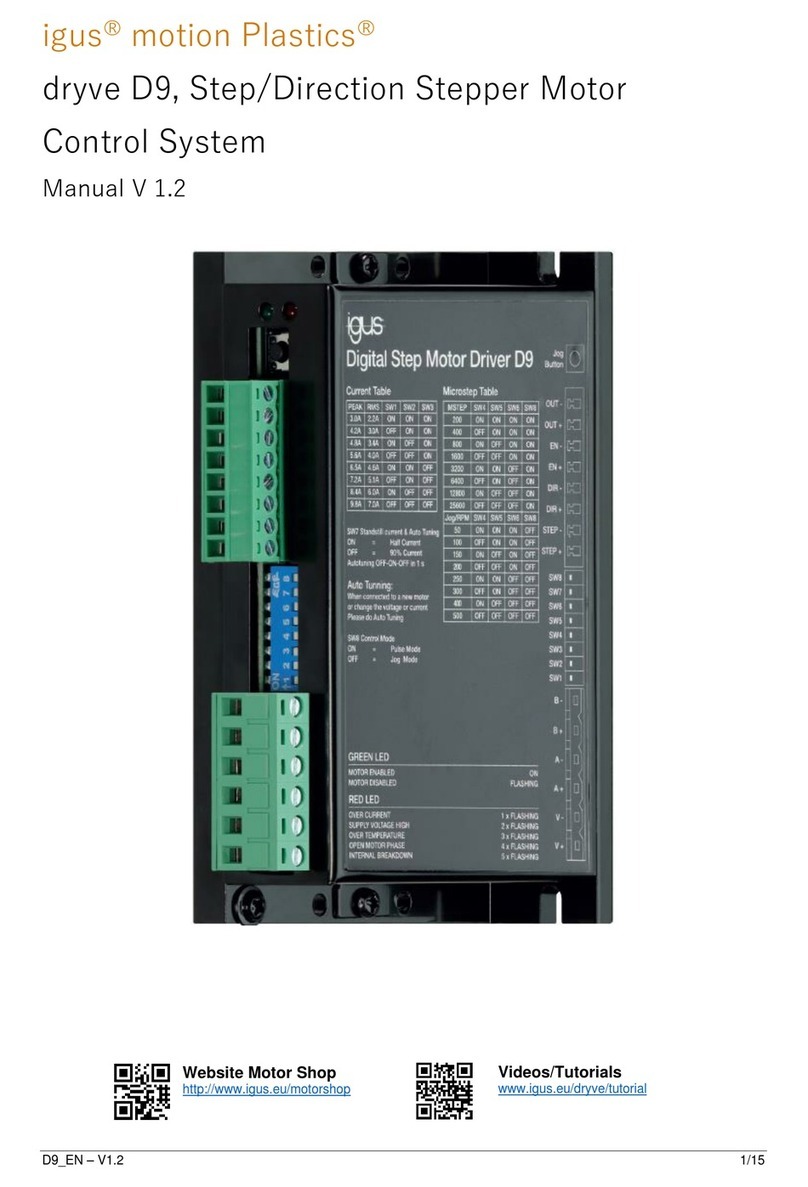
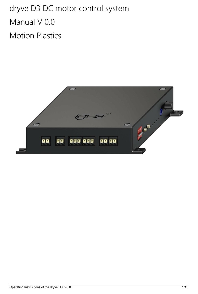
igus Motion Plastics dryve D1 User manual

Table of contents
2/121
Operating Manual dryve D1, ST-, DC-, EC/BLDC-Motor Control System - V2.4
Table of Contents
1Safety Instructions, Protective Measures and Guidelines............................ 5
1.1 Important Instructions........................................................................ 5
1.2 Qualified Personnel........................................................................... 5
1.3 Maintenance...................................................................................... 5
1.4 Safety Instructions............................................................................. 6
1.4.1 Information Classification.................................................................. 6
1.5 Electromagnetic Compatibility........................................................... 6
2Quick Setup...................................................................................................... 7
3Product Overview............................................................................................13
3.1 Operating Modes..............................................................................13
3.2 Technical Data .................................................................................14
4Installation.......................................................................................................16
4.1 Mechanical Installation.....................................................................16
4.2 Electrical Installation.........................................................................17
4.2.1 Power supply selection.....................................................................18
4.2.2 Pin Assignment ................................................................................21
4.2.3 Communication Interfaces................................................................26
5Initial Operation and User Interface...............................................................27
5.1 User Interface Connection Establishment........................................27
5.1.1 Connection Loss ..............................................................................28
5.2 User Interface Information................................................................29
5.2.1 Entering Parameters ........................................................................30
5.3 Start..................................................................................................31
5.3.1 Language.........................................................................................31
5.3.2 Measuring System............................................................................31
5.3.3 Movement Type ...............................................................................31
5.3.4 Time Units........................................................................................31
5.3.5 Configuration....................................................................................32
5.3.6 Firmware..........................................................................................32
5.3.7 Password .........................................................................................33
5.4 Motor configuration...........................................................................34
5.4.1 Motor................................................................................................35
5.4.2 User-Defined Motor..........................................................................36
5.4.3 Gear.................................................................................................37
5.4.4 Feedback .........................................................................................37
5.4.5 Closed-Loop.....................................................................................38
5.4.6 Self-Tuning.......................................................................................38
5.4.7 Brake................................................................................................39
5.4.8 Braking Resistor for EC/BLDC Motors .............................................40
5.4.8.1 Braking Resistor selection for igus motors.......................................40
5.4.8.2 Braking Resistor dimensioning for custom motors ...........................41
5.4.8.3 Braking Voltage Setting....................................................................44
5.5 Axis Configuration............................................................................45
5.5.1 Axis ..................................................................................................45
5.5.2 Motion Limits....................................................................................45
5.5.3 Limit Switch......................................................................................47

Table of contents
3/121
Operating Manual dryve D1, ST-, DC-, EC/BLDC-Motor Control System - V2.4
5.5.4 Homing.............................................................................................49
5.5.5 Analogue Absolute Feedback ..........................................................50
5.6 Communication ................................................................................51
5.6.1 Ethernet TCP/IP...............................................................................51
5.6.2 Transmission Protocol......................................................................52
5.6.3 Bus Systems....................................................................................53
5.6.4 Ethernet MAC address.....................................................................54
5.7 Inputs/Outputs..................................................................................55
5.7.1 Digital Inputs ....................................................................................55
5.7.2 Digital Outputs..................................................................................58
5.7.3 Digital Outputs Signal Characteristics..............................................58
5.7.4 Analogue Inputs ...............................................................................60
5.7.5 Digital Input Switch Characteristics..................................................60
5.8 Drive Profile......................................................................................61
5.8.1 Drive Mode Selection.......................................................................61
5.8.2 Test Function ...................................................................................62
5.8.3 Position Adoption .............................................................................62
5.8.4 Binary...............................................................................................63
5.8.5 Tipp/Teach.......................................................................................67
5.9 Oscilloscope and Controller Data.....................................................68
5.9.1 Oscilloscope Settings.......................................................................68
5.9.2 Controller Data.................................................................................69
5.9.3 Controller Data Fine-Tuning.............................................................70
5.10 Feed Rate Specification...................................................................71
5.11 Absolute Feedback...........................................................................73
5.12 Impulse check ..................................................................................73
5.12.1 Impulse Check with Physical Limitation............................................74
5.12.2 Impulse Check without Limit.............................................................74
5.13 Restore Factory Settings..................................................................74
6External Signal Exchange ..............................................................................75
6.1 Binary...............................................................................................75
6.1.1 Binary Mode Requirements..............................................................75
6.1.2 Binary Signal Sequence...................................................................76
6.2 Tipp/Teach.......................................................................................78
6.2.1 Tipp/Teach Requirements................................................................78
6.2.2 Tipp/Teach Signal Sequence...........................................................79
6.3 Step/Direction...................................................................................81
6.4 CANopen..........................................................................................82
6.4.1 Special Features of SDO/PDO Communication...............................82
6.4.2 Telegram Structure...........................................................................82
6.4.3 PDO mapping...................................................................................82
6.4.4 Network management......................................................................83
6.4.5 Necessary User Interface Settings...................................................84
6.4.6 State Machine Visualisation.............................................................85
6.4.7 Statusword.......................................................................................86
6.4.8 Controlword......................................................................................87
6.4.9 Parameter Entry...............................................................................87
6.4.10 Homing.............................................................................................88
6.4.11 Profile Position Mode .......................................................................89
6.4.12 Profile Velocity Mode........................................................................89

Table of contents
4/121
Operating Manual dryve D1, ST-, DC-, EC/BLDC-Motor Control System - V2.4
6.4.13 Cyclic Synchronous Position Mode..................................................90
6.4.14 Error.................................................................................................90
6.4.15 Object information............................................................................91
6.4.16 Overview of available objects...........................................................91
6.4.17 Detailed description of the objects for motion control.......................92
6.5 Modbus TCP Gateway...................................................................102
6.5.1 Necessary User Interface Settings.................................................102
6.5.2 Conversion of Integers into Double Word.......................................103
6.5.3 Communication Verification............................................................103
6.5.4 Byte Assignment Modbus TCP Gateway Telegram .......................104
6.5.5 RX/TX Telegram Example..............................................................105
6.5.6 Exception Codes Modbus TCP Gateway.......................................110
7Alerts and Errors...........................................................................................111
8Troubleshooting............................................................................................113
9FAQs ..............................................................................................................114
10 Accessories...................................................................................................115
11 Abbreviations................................................................................................116
12 Explanation of terminology..........................................................................116
13 Overview of input values..............................................................................118
14 Service ...........................................................................................................121

Safety Instructions, Protective Measures and Guidelines
5/121
Operating Manual dryve D1, ST-, DC-, EC/BLDC-Motor Control System - V2.4
1 Safety Instructions, Protective Measures and Guidelines
1.1 Important Instructions
Read this manual carefully before operating the dryve D1 motor control system. Familiarise with the safety instructions and
ensure that the required safety measures are followed.
This manual was created according to the best of our knowledge and belief. It is used for technical documentation and for
assisting the user during the initial operation. The warnings, cautions and instructions issued by igus® regarding the dryve D1
motor control system must in any case be passed on to the end user if the dryve D1 motor control system is used as part of an
overall system.
igus®undertakes warranties only for igus®products in accordance with the standards, norms and specifications given in this
manual. The guarantee covers only the replacement or repair of a defective dryve D1 motor control system. There is no liability
for consequential damage and consequential errors. The igus®GmbH does not take any responsibility for the integration of the
dryve D1 motor control system into the overall system. The responsibility for it lies with the plant designer or the end user.
Please observe the instructions under "Qualified Personnel". The company igus®assumes no liability for personal injury or
damage to property resulting from misuse or unauthorised technical modification of the dryve D1 motor control system.
The igus®GmbH reserves the right to make changes and improvements to the product or the technical documentation at any
time without prior notice.
The dryve D1 motor control system must only be used if:
- All information and safety instructions in this manual have been observed.
- The control system has been properly installed in a control cabinet in accordance with the instructions under Electrical
Installation (p.17)
- No changes have been made to the dryve D1 motor control system and it is in a technically flawless condition.
- The operating limits that are specified in Technical Data (p.14) are complied with.
1.2 Qualified Personnel
The operation of the product must only be carried out by qualified personnel.
- The personnel must have read and understood this manual and any other additional documentation that exists
- The personnel must be familiar with all relevant applicable standards, provisions and accident prevention regulations.
- The personnel must be able, due to their training, to anticipate or recognise any hazards that may arise when using the
control system.
- The personnel must ensure the safety of persons and objects when using the motor control system in the overall
system.
1.3 Maintenance
The dryve D1 is maintenance-free Apart from the connectors, the dryve D1 does not contain any components that the user can
replace from the outside. Never open the motor control system. If hardware problems occur, please get in touch with Customer
service (p.101).
Opening the housing will void the warranty.
Sebastian Probst

Safety Instructions, Protective Measures and Guidelines
6/121
Operating Manual dryve D1, ST-, DC-, EC/BLDC-Motor Control System - V2.4
1.4 Safety Instructions
1.4.1 Information Classification
The degree and type of hazard are marked unambiguously. All safety instructions are assigned to one of the following classes.
DANGER!
Safety instructions marked with DANGER indicate an imminently hazardous situation. A disregard of the notice inevitably
leads to a serious or even fatal accident.
WARNING!
Safety instructions marked with WARNING indicate a potential hazardous situation. Failure to observe the instruction can
possibly lead to a serious or even fatal accident or to equipment/property damage.
NOTE
Safety instructions marked with NOTE indicate a potential hazardous situation. Disregard of the notice may possibly result
in property damage.
1.5 Electromagnetic Compatibility
WARNING!
•Risk of injury due to interference with signals and devices
Disturbed signals can cause unforeseen device reactions.
Carry out the wiring in accordance with the EMC measures. Failure to follow these instructions can result in death, serious
injury, or material damage
Measures for EMC
Effect
Device assembly
Use cable clamps for the shield support,
connect metal parts over a large area.
Good conductivity due to surface contact.
Switching devices such as contactors, relays
or solenoid valves with interference
suppression units or spark suppressors (e.g.
diodes, varistors, RC elements).
Reduce mutual interference couplings.
Wiring
Keep cables as short as possible.
Avoid capacitive and inductive interference.
Do not place fieldbus cables and signal cables
for direct and alternating voltage over 60 V
together in a cable conduit.
Avoid reciprocal interference.
Earth the shields of digital signal cables at both
ends or by means of conductive connector
housings.
Avoid interference on control cables, reduce
emissions.
CAUTION!
Safety instructions marked with CAUTION indicate potential danger. Failure to comply with the notice may possibly result in
an accident or property damage.

Quick Setup
7/121
Operating Manual dryve D1, ST-, DC-, EC/BLDC-Motor Control System - V2.4
2 Quick Setup
Thank you very much,
for choosing the dryve D1 motor control system!
In the following, "quick initial operation" it is explained how to setup the dryve D1 and to control a stepper or DC-Motor with a
PC. The dryve D1 motor control system has been designed for operation with direct voltage. In this “quick initial operation” guide
a voltage of 24 V is being used.
Within just a few minutes, you will be able to operate your motor and even create your first fully automatic motion program.
Have fun!
Minimum requirements for initial operation of the dryve D1 with a PC
1. Voltage supply of 12 to 24 V with cables
2. Motor without feedback or
brake with appropriate cable
3. Ethernet cable
4. PC/Notebook

Quick Setup
8/121
Operating Manual dryve D1, ST-, DC-, EC/BLDC-Motor Control System - V2.4
Connect the components in accordance with the following diagrams and instructions. When connecting the cores, take note of
the following illustrations, which are intended to assist you.
1. Press the orange spring
into the connector by hand
or with pliers and hold
the spring down.
2. After removing the insulation, push
the cores (X1 and X5: 10 mm, X2: 8 mm)
deeply into the opening.
3. Release the orange spring
X1 Logic/Load Voltage Connector
1. Connect inputs X1.1 and X1.3 to the voltage supply
2. Connect input X1.2 to 0 V
X2 Digital Inputs Connector
1. Connect inputs X2.11 and X2.12 in accordance with the following diagram.

Quick Setup
9/121
Operating Manual dryve D1, ST-, DC-, EC/BLDC-Motor Control System - V2.4
X5 Motor Connector
For a Stepper Motor:
1. Connect inputs X5.1 - X5.4 in accordance with the following diagram.
For a DC-Motor:
1. Connect inputs X5.1 and X5.2 in accordance with the following diagram
IP address
The IP address which is assigned by the PC to the dryve D1 must be entered in the browser in order to establish a connection
to the dryve D1. If the dryve D1 is set to factory settings, this is done automatically.
Start an Internet browser (Google Chrome, Microsoft Edge etc.)
1. Connect the dryve D1 to the PC with an Ethernet cable.
2. Switch on the voltage supply the connected power supply.
3. The status display of the dryve shows the IP address
(e.g. 169.254.1.0). Type the address in the address bar
of your browser and press Enter.
4. You will be forwarded to the user interface.
5.
NOTE
The IP address is displayed anew after the ethernet connector is plugged out and in again
You can navigate using the tabs in the Navigation menu on the left-hand side
Help buttons display detailed descriptions of the individual settings.
Settings are changed via entering values, use of drop-down menus or sliders.

Quick Setup
10/121
Operating Manual dryve D1, ST-, DC-, EC/BLDC-Motor Control System - V2.4
After a connection has been established, the user is automatically transferred to the Start page of the dryve. All the necessary
settings for "quick initial operation" of the system have already been made ex works.
1. Specify the motor type
2. Select the igus®article number that is shown on the motor label
3. The parameters are set automatically
4. Leave the field by clicking in a free area
5. Click on "Apply"
If an customer motor is to be used, select "User Defined Article" at the "Article Number" dropdown menu and set the parameters
manually.

Quick Setup
11/121
Operating Manual dryve D1, ST-, DC-, EC/BLDC-Motor Control System - V2.4
1. Enter the Available Stroke and the Feed Rate. The Feed Rate defines the performed movement with each motor shaft
revolution. A possible value for the Available Stroke is for example 100 mm and 60 mm for the Feed Rate.
These values must be adopted to the used linear axis.
2. The "Movement Limits" must be specified to ensure a safe and reliable operation. If the user is operating the dryve D1
for the first time, choose low values such as:
Max. Velocity: 5 mm/s
Jog Velocity: 2 mm/s
Max. Acceleration: 100 mm/s²
Quick Stop: 1000 mm/s²
Following Error: 10 mm
Positioning Window: 0 mm
Positioning Time: 0 ms
3. In addition, the Reference Method must be set. Please select “SCP (Current Position)
All necessary communication settings for "quick initial operation" have been completed ex works.
1. Activate "DI 7 Enable" to enable the motor.
The set Motor Current will now be applied to the motor.
NOTE
As soon as the motor is supplied with electric current, it generates a holding torque. Make sure that the motor can move
freely.

Quick Setup
12/121
Operating Manual dryve D1, ST-, DC-, EC/BLDC-Motor Control System - V2.4
A first test run can be carried out to
test the wiring.
1. In the drop-down menu, select the "Binary" travel profile.
2. Use the "clockwise" and "counter-clockwise" buttons
under the table to move the motor.
4. Check to make sure that the "Clockwise" button
moves the motor shaft clockwise. If this
is not the case, disconnect the power supply and
check the wiring.
Now, an example of parameterisation can be carried out.
5. Using the buttons, move the carriage or rotation arm manually
to the middle of the distance available for travel.
6. Create the motion sequence shown in the table.
7. Select Row 1 by clicking in the number field of the row.
8. Start the program with the "Start" button.
The program can be stopped with the "Stop" button. If the program were to be started again,
it would continue from the marked row.
For igus®motors, the motor controller data have been set appropriately by default.
For user-defined motors, the controllers must be parameterised.
Use the help notes provided in the manual.
Congratulations!
You are now familiar with the basic functions of the dryve D1.

Product Overview
13/121
Operating Manual dryve D1, ST-, DC-, EC/BLDC-Motor Control System - V2.4
3 Product Overview
Ready to use instantly
The igus®dryve D1 uses standard commercially available Ethernet technology and therefore can communicate directly with
your network or a control unit (PC or PLC) via a standard Ethernet cable. The user interface is displayed in a browser of your
choice, without having to install any additional software. This makes it possible to parameterise the igus®dryve D1 motor
controller in an extremely short time.
Easy to control
You can use the simple intuitive user interface to parameterise positioning movements, accelerations and velocities of your
linear axis without the need of having any prior knowledge. Programs for continuously recurring movements can be created in
just a few seconds. A "Teach" function makes it possible to incorporate current actuator positions into the parameterisation with
just one click of the mouse.
Industry standards
The standard communication protocols CANopen and Modbus TCP Gateway make it very easy to connect the system to
industrial controllers such as the programmable logical controllers (PLC) as of Siemens or Beckhoff. The ten digital inputs, 5 of
which are binary coded for the preselection of 32 positioning movements, and five digital outputs enable extremely easy
communication with higher-level industrial controllers as well as with low-price open-source modules such as an Arduino or
Raspberry Pi.
Powerful technology
The igus® dryve D1 supports stepper, DC and EC/BLDC-Motors in Open-Loop as with Closed-Loop technology. With the
sinusoidally commutated Closed-Loop, a Stepper Motor can be operated as a servo motor. Due to the Closed-Loop, the Motor
Current is controlled according to the load case, because of which the operating temperature of the dryve D1 and the connected
motor can be lowered.
To optimally attune the igus®dryve D1 to a motor, current, velocity and position control parameters are able to be tuned. In
addition an automatic Step Mode selection is available.
The system can be set to the "zero point" by different external and internal homing methods. Position monitoring with automatic
Following Error correction and Closed-Loop control is available via different Feedback systems. The supported load voltage of
up to 48 V ensures high motor velocities, whereby the high rated current of 7 A and peak currents of up to 21 A (depending on
type of motor) enable powerful and dynamic movements.
I²T motor protection
To protect motors against thermal overload, the igus®dryve D1 is equipped with I²T protection for overload monitoring.
I²T protection makes it possible to safely operate the motor for a certain time even if used with overload conditions.
3.1 Operating Modes
In the following section, the different operating modes of the dryve D1 motor control system are described. Due to the different
operating modes, the arrangement of the electric wiring changes depending on the intended application.
Binary
The "Binary" operating mode offers up to 32 individual positioning movements parameterised with different motion types and
movement data such as accelerations and velocities. It is possible to generate a simple programme sequence executed via the
user interface or control it entirely with a higher-level control system via the Digital Inputs/Outputs
In addition, the target position of the command can be specified in the absolute reference system of the axis or relative to the
current position.
It is possible to execute manually controlled movements via the user interface.
Tipp/Teach
With the "Tipp/Teach" mode, positioning movements can be executed by external switches. The motor can be moved manually
with these external switches in the desired direction at a pre-set acceleration and velocity.
Up to 8 individual positioning movements can be pre-set via the user interface. The target positions can be altered with the
external switches without the user interface being used.
Step/Direction
In the "Step/Direction" mode, a step frequency and a direction signal are applied to the dryve D1 motor control system by a
master controller. The acceleration and the speed are fed to Digital Input 1 and the movement direction is fed to Digital Input 2.
BUS communication
The dryve D1 motor control system can be controlled by an external higher-level control system via the CANopen protocol or
the Modbus TCP Gateway protocol.

Product Overview
14/121
Operating Manual dryve D1, ST-, DC-, EC/BLDC-Motor Control System - V2.4
3.2 Technical Data
Mechanical Data
D x W x H in millimetres, incl. connectors & mounting elements
124 x 31 x 139
Weight in grams
200 g
Electrical Data
CAUTION!
•Risk of destruction
An operating voltage above the voltage indicated in the technical data will destroy the dryve D1
Select an operating voltage within the voltage range specified in the technical data.
Induced voltages from other electrical loads and/or motors may result in a function interference. Allow corresponding safety
reserves and countermeasures.
Make sure that your voltage supply is energy feedback protected if the logic voltage and load voltage are supplied from the
same power supply unit or from the same transformer.
CAUTION!
•Danger of burning
The housing of the dryve D1 motor control system as well as the driven motor may reach very high temperatures.
Revision
HW: RE, FW: G
Voltage Supply
Logic
12 to 24 V, max. 26 V
Load
12 to 48 V, max. 50 V
Digital I/O
5 to 24 V, max. 26 V
Current Drain Logic
Min. 75 mA to 225 mA
Current Drain Load
5 mA to 7 A, max 22 A (Boost)
Current Drain Digital I/O
35 mA to 1,1 A
Motor Types
ST
2 Phase Stepper Motor, bipolar
DC
DC Motor
EC/BLDC
Electronically Commutated Motor
Continuous Motor Current
7 A
Boost Current
Output Duration
Max. 2 s
ST
10.5 A
DC
14 A
EC/BLDC
21 A
Load Power Output
Max. 340 W
Peak Power Output
Max. 1000 W
Dissipation Loss
Min. 2,5 W (idle)
Max. 15 W (full load)
Max. Velocity
Stepper
25,000 steps/s
DC
Motor dependent
EC/BLDC
Min.14,000 rpm
Feedback
Permissible Feedback Types
5 V
Internal Voltage Source
5V ±10%
50 mA to 120 mA

Product Overview
15/121
Operating Manual dryve D1, ST-, DC-, EC/BLDC-Motor Control System - V2.4
Feedback
Internal Voltage Source
Short Circuit Protected
Resolution
1 –4096 increments
Encoder Input Frequency
Min. 300 kHz
Hall Sensor Input Frequency
5 kHz
Holding Brake
Voltage output
24 V
Current output
Max. 1 A
PWM at 48 V UBat X 1.1
312 kHz
Braking Resistor
External resistor between X5.4 and X5.5
24 V at X1.1
Min. 0,8 Ω
48 V at X1.1
Min. 1,7 Ω
Frequency
24 kHz
Overload protection shut off
After 1 s permanent trigger
Motor and encoder cable lengths
< 30m
Digital Inputs
10 Digital Inputs
Short-Circuit Protected
Galvanically Separated by Optocoupler
ULow 10% UBX2.11
UHigh 60% UBX2.11
PNP
Pull-Down, internal
NPN
Pull-Up, internal
Maximum Frequency DI 1 and DI 2
25 kHz
Maximum Frequency DI 3 to DI 10
100 Hz
Debounce Filter DI 1 to DI 10
(not at Step/Direction Mode)
10 ms
Current Drain
5 V at X2.11
5 mA
24 V at X2.11
8 mA
Digital Outputs
5 Digital Outputs
Short-Circuit Protected
Galvanically Separated by Optocoupler
PNP
Pull-Down, internal
Output Current
Max. 200mA
Output Voltage
UBat X2.11
Analogue Inputs
Voltage Interval
± 10V
Input Resistance
50 kΩ
Accuracy
± 0.1 V
Signal Filter
16 ms, level dependent
± 10 V Signal
12 Bit
0-10 V Signal
11 Bit
Internal Voltage Supply
10 V ±2%
Max. 15 mA
Regulated
Short Circuit Protected
External resistor between X4.1 and X4.4
700 Ω to 50 kΩ

Installation
16/121
Operating Manual dryve D1, ST-, DC-, EC/BLDC-Motor Control System - V2.4
Environmental Conditions
WARNING!
- Danger of malfunction
- Fire hazard
- Explosion hazard
- Danger of electric shock
Never operate the dryve D1 motor control system in water or in an aggressive, flammable or explosive atmosphere.
Ambient Temperature
Operation
-20 °C to +45 °C
Transport
-40 °C to +60 °C
Storage
-40 °C to +60 °C
Relative Humidity
≤ 90 %, non-condensing
Protection Class
IP 30
Degree of soiling according to EN 61010
1
MTTF value @ 25°C
64,72 Years
4 Installation
4.1 Mechanical Installation
- Installation in a control cabinet by mounting it on a TS 35 supporting rail (EN 50022) or by removing the mounting clip
and screwing the base of the housing directly onto a mounting plate.
- The device must be aligned vertically. For horizontal alignment, the maximum power must be reduced by 30% to
prevent overheating
- The installation site must be free of extreme vibrations or shocks.
- Minimum free space above and underneath the device: 50 mm
- The ventilation openings are to be kept free
- 35 mm of space for plug-in connectors and cables must be kept free in front of the device.
- If several dryve D1 devices are placed next to each other, a space of 10 mm must be kept in between (applies for
continuous operation)
- If several dryve D1 devices are placed without space in between, the maximum continuous current must be reduced to
5.5 A or an active cooling system must be used (applies for continuous operation)
- The heated air flow of other devices and components must not be led through the area of the dryve D1.

Installation
17/121
Operating Manual dryve D1, ST-, DC-, EC/BLDC-Motor Control System - V2.4
4.2 Electrical Installation
WARNING!
- Danger of electrical voltage
- Danger of electric arcs
Danger of injury and destruction of components.
Always turn off the power before disconnecting or making electrical connections in the system. Secure the power supply
against restart.
After switching the device off, wait at least 5 minutes. Check for the absence of voltage before working on the system.
Danger of electric arcs with improperly mounted electrical connections.
Wires connected to the dryve D1 must not have exposed wire ends without insulation. Check all connections for being
secured.
In the event of a fault, the motor housing can carry high currents. Connect the motor housing to the ground conductor via the
motor mounting components. In this regard, please observe the instructions in EN 60204-1.
CAUTION!
The maximum current of a Stepper Motor can be above the indicated rated current. The actual occurring current must be
considered for installation.
Any current setting are made at your own risk.

Installation
18/121
Operating Manual dryve D1, ST-, DC-, EC/BLDC-Motor Control System - V2.4
NOTE
Follow the instructions regarding PELV circuits (p.20) and use suitable components for earthing.
NOTE
The logic voltage does not supply the motor windings. If the logic voltage supply collapses, the motor will stop in an
uncontrolled manner or might even accelerate if build in in vertical or rotating applications.
4.2.1 Power supply selection
For the correct dimensioning of the power supplies to be used, various aspects must be considered
1. Number of used motor controller per power supply
2. Maximal current draw of each motor (consider the set Boost)
3. Maximal current draw of used peripheral devices (e.g. sensors and other devices)
4. Maximal current draw of the Logic
The current draw must be added voltage wise. This sum defines the minimal current supply capacity of the power supply.
NOTE
If different power supplies are used for the load and logic voltage, the grounds of both power supplies must be connected to
create a common potential.
CAUTION !
The connection terminals are designed for single wires.
A firm connection cannot be guaranteed due to improper multiple occupancy. There is a risk that wires may slip out of the
terminals and cause short circuits.
If several signals/wires have to be connected to one terminal, they must be brought together via an external terminal and
connected from there with a single wire.

Installation
19/121
Operating Manual dryve D1, ST-, DC-, EC/BLDC-Motor Control System - V2.4
The arrow marks pin 1

Installation
20/121
Operating Manual dryve D1, ST-, DC-, EC/BLDC-Motor Control System - V2.4
Connector
Pin
Assignment
Description
X1
Logic/Load-Voltage
1
12 - 48 V Load
Motor Voltage Supply (necessary for operation)
2
0 V Logic/Load
Common Ground (necessary for operation)
3
12 - 24 V Logic
Controller Voltage Supply (necessary for operation)
X2
Digital Inputs
Binary
Tipp/Teach
Step/Direction
1
Digital Input 1
Bit 0
Bit 0
Step
2
Digital Input 2
Bit 1
Bit 1
Direction
3
Digital Input 3
Bit 2
Bit 2
-
4
Digital Input 4
Bit 3
Jog left
-
5
Digital Input 5
Bit 4
Jog right
-
6
Digital Input 6
Start
Start/Teach
-
7
Digital Input 7
Enable
Enable
Enable
8
Digital Input 8
Limit Switch positive
Limit Switch positive
Limit Switch positive
9
Digital Input 9
Limit Switch negative
Limit Switch negative
Limit Switch negative
10
Digital Input 10
Stop/Reset
Stop/Reset
Reset
11
5 - 24 V
External I/O Supply necessary for operation)
12
0 V
External I/O Supply (necessary for operation)
X3
Digital Outputs
1
Digital Output 1
Ready
2
Digital Output 2
Active
3
Digital Output 3
Referenced
4
Digital Output 4
Alert
5
Digital Output 5
Error
X4
Analog Inputs
1
10 V
Supplied by controller
2
Signal 1
Velocity and position setpoint
3
Signal 2
Position feedback
4
0 V
Supplied by controller
X5
Motor/Brake/
Braking Resistor
1
A (ST), U (EC/BLDC), + (DC)
Motor connection
2
A/ (ST), V (EC/BLDC), - (DC)
Motor connection
3
B (ST), W (EC/BLDC)
Motor connection
4
B/ (ST), RBrake (EC/BLDC)
Motor and Braking Resistor connection
5
Ground, RBrake (EC/BLDC)
Ground and Braking Resistor connection
6
24 V Holding Brake
Holding Brake connection
7
0 V Holding Brake
Holding Brake connection
X6
Feedback
1
5 V
Feedback
2
0 V
Feedback
3
A
Feedback
4
A/
Feedback
5
B
Feedback
6
B/
Feedback
7
N
Feedback
8
N/
Feedback
9
H 1/U (EC/BLDC), 1 (DC)
Feedback
10
H 2/V (EC/BLDC), 2 (DC)
Feedback
11
H 3/W (EC/BLDC)
Feedback
X7
CANopen
1
-
NC
2
CAN_L
CAN Signal Low
3
CAN_GND
CAN Masse
4
-
NC
5
-
NC
6
-
NC
7
CAN_H
CAN Signal High
8
-
NC
8
-
NC
X8
Ethernet
Modbus TCP Gateway
Standard assignment according to
TIA-568A und TIA-568B
X9
Status Display
General electrical installation information
The dryve D1 is designed for DC voltages.
All voltage specifications listed in this operating manual therefore are to be considered as DC voltage.
This manual suits for next models
1
Table of contents
Other igus Control System manuals
Popular Control System manuals by other brands
Johnson Controls
Johnson Controls System 450 Series Technical bulletin

Inovance
Inovance Monarch NICE Series user guide
Maple Systems
Maple Systems HMC7030A-L installation guide
Tormatic
Tormatic HA MS 400V Assembly and operating instructions
RichAuto
RichAuto AutoNow F141 user manual
Badger Meter
Badger Meter MDS 2000 user manual

