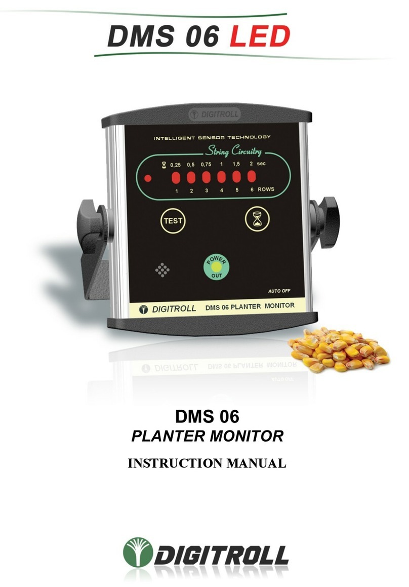
Digitroll DMS 08 LCD User manual

2019. 09. 10. – rev. C
DMS 08 LCD
(version 1.x)
DMS 08 LCD
seeding control system for
PLANTERS
USER’S MANUAL
DIGITROLL

SYSTEM DRAFT
2
SYSTEM DRAFT
Seeding control system for planters 1-8 rows with area counter
DS 1000 -custom designed for seeder type, placed in seed tube
DS 2000 - custom designed for seeder type, placed in coulter
RED
BLUE

3
CONTENT
SYSTEM DRAFT ........................................................................................................... 2
GENERAL DESCRIPTION ........................................................................................... 4
MOUNTING ................................................................................................................... 5
MONITOR FRONT ........................................................................................................ 6
SWITCH ON ................................................................................................................... 6
SYSTEM TEST .............................................................................................................. 7
MENU ............................................................................................................................. 8
SEEDING CONTROL .................................................................................................... 9
SETTING BASIC DATA ............................................................................................. 10
TROUBLESHOOTING ................................................................................................ 12
MAINTENANCE, STORAGE ..................................................................................... 15
WARRANTY PROVIDED .......................................................................................... 15
MISSING SEED TIME/SPEED/SEED SPACING TABLE ........................................ 16

GENERAL DESCRIPTION
4
GENERAL DESCRIPTION
DMS 08 LCD MONITOR
· illuminated LCD display
· massive aluminium housing
· audible and visual alarms
· 5 selectable languages
· nonvolatile memory for safe storage of measured and adjusted data
· auto off
SYSTEM CONSTRUCTION
· infrared sensation
· connected in linear string system up to 8 rows
· modules are exchangeable, their sequence is determined automatically
when connected
· harness-free network - easy cabling and mounting
SYSTEM TEST
Sensordiagnostics.
· automatic recognition and readiness test of photosensors
· dusty or blockaged sensor display
SEEDING CONTROL
· Simultaneously detected seeding continuity on all rows
· Selectable seed dize and shape
· Adjustable missing seed time interval for error signal
· Easy to use seeding blockage control mode. Unnecessary any settings.
HECTARE COUNTING
· Measure and store total and partial seeded area to 999,99 ha
· Start/stop measuring by signal of photosensors
SYMBOLS APPLIED
*
Seed
C
Recognized photosensor
O
Dusty photosensor
X
Fully endusted, clogged or defected photosensor

MOUNTING
5
MOUNTING
MONITOR
Place the monitor on a clearly visible place in the tractor cabine and fix it with
the U-bracket and bolts, up or bottom position to avoid direct sunlight on LCD.
The display is illuminated which enables nighttime use with superb visibility
• The monitor is connected optimally after a fuse (max. 3A) on 12 VDC,
taking care of the right polarity.
• Connect the extension cable of modules to the monitor.
• Do not connect in line with other disturbing signal emitter
devices.
• Welding works are allowed only when both power cables of
the monitor are disconnected from the tractor’s electronic
system.
SPEED SENSOR FOR HECTARE COUNT
Mount speed sensor in front of a non-slipping wheel.
The best is a freewheel which sized to give at lest 1
signal in a distance traveled between 0,2 – 0,99 m.
The speed sensor gives you information about the
distance traveled.
Speed sensors are inductive sensors, in proximity of an iron part e.g. bolt heads
give a signal. If distance between sensing bolt heads would be more than 1
meter, additional bolt signallers has to be mounted. This way, during calibration
the distance traveled in 100 bolt signals remains under 100 meters.
Checking operation:
• red LED at the end of speed sensor
• a symbol of speed sensor is blinking on monitor front
Important: when planning the placement of speed sensor regard the risk
of straw residues or pebbles, they may hurt the sensor.
4-6 mm
Útjeladó
Csavarfej
Very important to adjust speed
sensor within the sensing distance,
generally between 4-6 mm from bolt
head.

MONITOR FRONT
6
MONITOR FRONT
Spin up in settings options.
One touch: spin up
Pushed continuously: spin up in quick time
SWITCH ON
Following switch on appear the system test, which is followed by the display
of test results.
system test
settings
horn
wheel-LED
functions, modes
On, 12V out - light
Shorted cable - dark
Off - dark
backlighted LCD
display
Switch indicator
(red LED)

SYSTEM TEST
7
SYSTEM TEST
The system test is executed:
• every switch on,
• by pressed button on screen of seed control mode
• automatically by change settings of seed sensors.
During test process the monitor detects:
• which modules are connected to the system (seed sensors, speed
module),
• what is the readiness for operation of connected seed sensors
(operability, dust level check),
• Sends data to adjustable modules (DS2000).
Having the test finished, the ‘found’ modules are presented on display:
TEST ........
No photosensors!
Cx COCC
COperating sensor
Odusty sensor
x seeding blockage
unsuccessful test result
TEST function may be used when there is
no seeding in progress!

MENU
8
MENU
Control of Seedong
Blockage
Setting Missing Seed Time
Reset Hectare
Settings
Entry pf Distance Traveled in
100 Speed Signals
Entry of Working Width
100 Speed Signal Count
Setting Seed Size
Language Selection

SEEDING CONTROL
9
SEEDING CONTROL
The monitor simultaneously detects seeding continuity in all rows. Where seed
drop is missing for longer time than preset limit value, seed symbol of that row
(*) will disappear from display and alarm sounds in according length.
During the turnings at landmarks alarm is disabled automatically.
Example of display at a 6-row planter:
Missing seed time: 1.5 sec.
nnnnnnn 015.26
seed sensors
hectare
Rows 1,3,5 and 6 are continuously
seeding within preset limit value.
In rows 2 and 4 seeds are missing within
the 1.5 seconds preset limit value.
nCnCnn 018.48

SETTING BASIC DATA
10
SETTING BASIC DATA
MISSING TIME INTERVAL ADJUSTMENT
See also table on page 16.
CANCEL HECTARE DATA
OTHER SETTINGS
SELECTION OF SEED SIZE
Q*: 1.50 sec
You can set missing seed time interval between
0.25 – 2.00 seconds in 6 steps.
QReset area
push button for at least 2 seconds
2 sec.
QSettings
return to the seeding control mode
to next options
Q*: 6Ý9mm
change size
In order to reach more precise seed detection
when using DS 2000 seed sensors, main seed
characteristics like size shape must be entered.
It brings more efficiency in recognition of
double or triple seed drops.

SETTING BASIC DATA
11
100 SPEED SIGNAL COUNT
This is a side function to get information about distance traveled in 100 speed
signals.
Pull/tow seeding machine on field until 100 speed signals are counted, then
measure distance traveled between 0. and 100. signals with a measure tape
on the ground. Enter distance value in the monitor in centimeters.
Speed sensor is an inductive sensor which detects bolt heads of a driven wheel.
In case of individual installation the number of signalling bolt heads must be
enough to provide at least one signal at every 30-60 cms distance traveled and
it may not exceed 100 cms.
Readiness for operation is indicated by a flashing SPEED SENSOR LED
on the monitor. Accurate measurement can be reached if speed sensor exactly
aligns bolt head when starting calibration. Besides signal counter on screen
watch this red LED as well, which shows you how sharply the sensor aligns
the bolt head, both at start and end points.
SETTING OF DISTANCE TRAVELED IN 100 SPEED SENSOR
SIGNAL
The distance traveled can be determined either:
• by MEASUREMENT: with a measure tape ( it is always more
accurate method since average slip is also included)
• by CALCULATION: ×wheel perimeter (cm)
ENTRY OF WORKING WIDTH
Seeding machine working width is adjustable between 0.75-30 meters
Working width can be calculated: row number multiplied by row spacing.
100 sign: 000
Dist: 58.4 m
One touch: spin up
Pushed continuously: spin up in quick time
W.width: 04.5 m
One touch: spin up
Pushed continuously: spin up in quick time
100
number of bolt heads

TROUBLESHOOTING
12
LANGUAGE SELECTION
The program enables the selection of one language out of the 5 followings: Hungarian,
Slovakian, Ukrainian, English, German.
TROUBLESHOOTING
THE MONITOR DOES NOT FUNCTIONING, NO LIGHTS ON
DISPLAY
• The monitor does not receive 12 VCD power supply (min. 8,5V)
• Wrong polarity battery lead connection
• Missed to switch ON button on the back side of monitor
• Defected main switch or electronic part
There is an auto-reset fuse built in the monitor, so it is unnecessary to dismount monitor
to replace fuse. Let official service repair it.
THE MONITOR WORKS BUT “POWER OUT” LED DOES NOT
LIGHTS OR IT BLINKS
This LED indicates power supply and get off when overloaded.
Signs: LED lights ® normal function
LED blinks ® partial overload
LED off ® total external short circuit
Probe: Disconnect modules from monitor:
• If LED lights (after a short pause) - external short circuit
• If LED remains dark - the monitor is defect
Possible reasons of external short circuit:
• Cable pinch-in :
Troubleshooting: systematically disconnect modules started from
monitor side. If LED lights, connect again (no problem with cable
until this point) and disconnect next connector until you find short
circuit area.
Defected seed module:
Troubleshooting: by doing the same disconnection process you can find the
defected unit that caused short circuit. The presence of power supply in seed
modules is also indicated by built-in LEDs.
QEnglish

TROUBLESHOOTING
13
THE MONITOR FUNCTIONS ‘POWER OUT’ LIGHTS, BUT
FOLLOWING THE TEST SENSOR SIGNALS ARE PARTIALLY
OR TOTALLY MISSING
• Caused by mistaken switch off of row detection, some rows are missing
from screen. Check again and reset row detection where necessary. (See
SETTING ROW SKIP)
• Hurt cable or connector, or defected module.
Troubleshooting: push TEST button and note the number of last detected
seed module.
E.g. Only 8 sensors are detected of 12. The source of problem can be at the
output side of module 8, or more probably in module 9.
a., LEDs do not light from module 9 up.
- battery leads are probably hurt
- connector is defected between modules 8 and 9.
- output side of module 8 or the module 9 is defected
b., LED lights at modules 9,10,…etc.
- Power supply is in order, communication cables are hurt between
modules 8 and 9 (or connector is defected).
- output side of module 8 or the module 9 is defected.
the easiest way to find defect in a linear system is that you disconnect and bridge
supposed defect module:
• skipping module 9, connect module 8 directly to module 10
• skipping module 8, connect module 7 directly to module 9
Push TEST to verify, replace defected module
Important notice: the monitor numbers the seed modules according to
connection order. Consequently, if a module removed, the numbers of
next modules jump one back E.g. if we remove module 9, module 10
becomes module 9, and so on…
Last
detected
module
9.7. 8. 10.
próba próba
probe
probe
3.
4.
5.
6.

TROUBLESHOOTING
14
THE MONITOR INDICATES BLOCKAGE AT A SEED
MODULE FOLLOWING TEST AND EVEN AFTER CLEANING
Defected seed module.
Troubleshooting: insert a long stick inside the seed sensor. If LED gets dark for
a second: it works. If not: sensor is defected.
THE MONITOR INDICATES IRREGULAR SEED DROPS
WHEN SEEDER STOPPED
• Seeds or seed fragments picked up accidentally by the air-flow are
detected by the seed sensor. Sensitivity was set too high – adjust higher
time limit to reduce sensitivity.
• Sensor is defected
THERE IS NO SEED DETECTION AT A PROPERLY
WORKING SEEDER, TEST FINDS SEED MODULES, NO DUST
INDICATED
• Small sized seeds at low rate seeding – adjustment to small seed size and
missing seed time interval to higher.
• Module is defected, check it by blinking LED with a long stick inserted
inside.

MAINTENANCE, STORAGE
15
MAINTENANCE, STORAGE
• The most important is keep cables and connectors unhurt and check
then regularly.
• Always clean sensors at the end of seeding season, close the end of
extension cable with the waterproof seal.
• Do not expose the monitor to direct water, do not store it under –20 C
and above + 40 C temperature, protect it from excessive heat and dust.
Remove the monitor from the cabine for winter and store at a dry,
vapourfree place.
• Protect monitor front, display and buttons from strong mechanical
impacts. Clean the monitor with a slightly wet wipe.
• There is no battery in the monitor and there are no other parts that
require maintenance.
WARRANTY PROVIDED
See attached warranty card.

MISSING SEED TIME/SPEED/SEED SPACING TABLE
16
MISSING SEED TIME/SPEED/SEED SPACING TABLE
speed: 4 km/h
speed: 9 km/h
Missing 6
0,25
0,50
0,75
1,00
1,50
2,00
Missing 6
0,25
0,50
0,75
1,00
1,50
2,00
seed (m)
0,28
0,56
0,83
1,11
1,67
2,22
seed (m)
0,63
1,25
1,88
2,50
3,75
5,00
Seed space (cm)
Number of seed (piece)
Seed space (cm)
Number of seed (piece)
6
4
9
13
18
27
37
6
10
20
31
41
62
83
8
3
6
10
13
20
27
8
7
15
23
31
46
62
10
2
5
8
11
16
22
10
6
12
18
25
37
50
12
2
4
6
9
13
18
12
5
10
15
20
31
41
14
1
3
5
7
11
15
14
4
8
13
17
26
35
16
1
3
5
6
10
13
16
3
7
11
15
23
31
18
1
3
4
6
9
12
18
3
6
10
13
20
27
20
1
2
4
5
8
11
20
3
6
9
12
18
25
22
1
2
3
5
7
10
22
2
5
8
11
17
22
24
1
2
3
4
6
9
24
2
5
7
10
15
20
26
1
2
3
4
6
8
26
2
4
7
9
14
19
speed: 6 km/h
speed: 10 km/h
Missing 6
0,25
0,50
0,75
1,00
1,50
2,00
Missing 6
0,25
0,50
0,75
1,00
1,50
2,00
seed (m)
0,42
0,83
1,25
1,67
2,50
3,33
seed (m)
0,69
1,39
2,08
2,78
4,17
5,56
Seed space (cm)
Number of seed (piece)
Seed space (cm)
Number of seed (piece)
6
6
13
20
27
41
55
6
11
23
34
46
69
92
8
5
10
15
20
31
41
8
8
17
26
34
52
69
10
4
8
12
16
25
33
10
6
13
20
27
41
55
12
3
6
10
13
20
27
12
5
11
17
23
34
46
14
2
5
8
11
17
23
14
4
9
14
19
29
39
16
2
5
7
10
15
20
16
4
8
13
17
26
34
18
2
4
6
9
13
18
18
3
7
11
15
23
30
20
2
4
6
8
12
16
20
3
6
10
13
20
27
22
1
3
5
7
11
15
22
3
6
9
12
18
25
24
1
3
5
6
10
13
24
2
5
8
11
17
23
26
1
3
4
6
9
12
26
2
5
8
10
16
21
speed: 8 km/h
speed: 12 km/h
Missing 6
0,25
0,50
0,75
1,00
1,50
2,00
Missing 6
0,25
0,50
0,75
1,00
1,50
2,00
seed (m)
0,56
1,11
1,67
2,22
3,33
4,44
seed (m)
0,83
1,67
2,50
3,33
5,00
6,67
Seed space (cm)
Number of seed (piece)
Seed space (cm)
Number of seed (piece)
6
9
18
27
37
55
74
6
13
27
41
55
83
111
8
6
13
20
27
41
55
8
10
20
31
41
62
83
10
5
11
16
22
33
44
10
8
16
25
33
50
66
12
4
9
13
18
27
37
12
6
13
20
27
41
55
14
3
7
11
15
23
31
14
5
11
17
23
35
47
16
3
6
10
13
20
27
16
5
10
15
20
31
41
18
3
6
9
12
18
24
18
4
9
13
18
27
37
20
2
5
8
11
16
22
20
4
8
12
16
25
33
22
2
5
7
10
15
20
22
3
7
11
15
22
30
24
2
4
6
9
13
18
24
3
6
10
13
20
27
26
2
4
6
8
12
17
26
3
6
9
12
19
25
Example: speed = 8 km/h Seed spacing = 16 cm
We should like to get error signal if 2-3 seed is missing subsequently. Select the
0,25 sec. value. The accomplished distance is 0,56 m, after this distance without
seeding the error signal is appear.
Table of contents
Other Digitroll Control System manuals
Popular Control System manuals by other brands
eqss
eqss OverWatch 6253 installation manual
Motorline professional
Motorline professional MR-12 User's and installer's manual
HandyTrac
HandyTrac Key Control System installation & operating manual
Mitsubishi Electric
Mitsubishi Electric TC-24A installation manual

DuroZone
DuroZone JTZ-HP manual

Schweitzer Engineering Laboratories
Schweitzer Engineering Laboratories SEL-421-7 manual
