Ihagee EXA IIa User manual

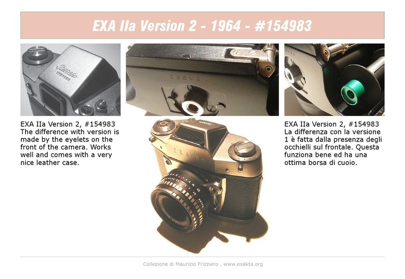
E X A • IIa

ii

iii
9
10 12 217 14
16
15
8
6
5
4
1
3
11 7

iv
14 13 12 19 11 9
15
32
28
27
2625312423
22
21
20
16

v
318 17
30
31
29
The most importance
operating controls of the
EXA IIa
1. Lens
2. Red dot on the lens
3. Release rocker/release knob on lens-
es with automatic diaphragm
4. Diaphragm setting ring
5. Distance setting ring
6. Depth of field setting ring
7. Red dot on camera
8. Flash contact
9. Frame counter
10. Rewind de-clutching button
11. Rapid-wind lever for winding shutter
and tensioning film simultaneously
12. Pentaprism viewfinder

vi
13. Shutter release lock
14. Rewind crank
15. Film-speed and type indicator
16. Shutter-speed setting ring
17. Shutter release button
18. Locking lever for lens bayonet
19. Eyepiece of pentaprism viewfinder
20. Rewind-spindle dog
21. Cassette chamber for unexposed
film
22. Guide plate
23. Film guide roller
24. Film guide runner
25. Film gate with focal-plane shutter
blind
26. Film transport sprockets
27. Take-up spool for exposed film
28. Take-up chamber (for spool and
cassette)
29. Detachable camera back (with inter-
changeable film pressure plate)
30. Rotating milled ring for locking
camera back
31. Tripod bush
32. Film-advance spindle dog

1
As you start working with your new EXA IIa, we
would like to congratulate you on your choice
and wish you lasting enjoyment and successful
results with your new camera.
You have invested in a photographic instrument
of amazing versatility in the EXA IIa, which,
despite its simplicity of operation, will provide
all the facilities you need to master every field
of miniature photography as your own require-
ments become more ambitious. In return, this
camera makes only one demand upon you, that
in your own interests you should learn all about
its operation to get the best performance out
of it. Do not hesitate, there- fore, to read these
instructions carefully before using the camera;
begin by practicing the operation of the con-
trols with the camera empty, and then learn how
to load and unload it using an old film. When
you can perform all these operations perfectly,
you will be that much more certain of obtaining
successful results. And now fold out t he oppo-
site page of this manual to the left so that you
can always keep the illustrations in front of you
whilst reading the text.
Obviously there is little need for us to point out
all the major advantages of the EXA IIa, since it
was these which led you to select this camera
in the first place. The single-lens reflex focusing
system, which ensures that you can always see
a brilliant, erect, laterally-correct and magni-
fied image in the pentaprism viewfinder of the
EXA IIa, will solve almost all your photographic
problems: with the sole assistance of the paral-
lax-free image you can select your subject, focus
the image and check the depth-of-field range
with equal accuracy, no matter whether you are
taking close-up pictures with extension tubes, or
long-distances hots with special telephoto lens-
es. The quietly- operating focal plane shutter,
the rapid-wind lever and the reliable film trans-

2
port mechanism are all equally delightful to use.
Also, take a look at the vast range of accessories
for the EXA IIa which make such light work of
many otherwise impossible assignments.
And now let us give you a good start toward
taking pictures with your EXA IIa.
IHAGEE KAMERAWERK AG. DRESDEN A 16.
This instruction manual was reproduced from the scanned original ‘EXA IIa Instruction Manual” by Ihagee Kamerawerk AG Dresden A 16. Lay-
out in Adobe InDesign CC and pictures re-touch in Adobe Photoshop CC. Typeface in this book are Avenir, Avenir Next and Adobe Myriad
Pro.

3
Removing and replacing the
camera back
Turn milled ring (30) in the base of the camera
until red dots are opposite each other. Grip
the camera with both hands, with the back (29)
facing upwards and the pentaprism viewfinder
(12) pointing towards you. Press gently on the
back (29) with both thumbs and slide it out from
under the chrome-plated top capping, until
the red dot above the film gate (25) becomes
visible (Fig. 1). Then lift the back (29) out of its
guide channels.
To replace the camera back (29), insert it from
above into the guide channels on either side
of the camera body-red dots must be opposite
each other-so that the top edge of the back is
in line with the red dot (just as for removing the
back). Then push the back right home, and turn
milled ring (30) until the two red dots are no
longer opposite each other.
Fig. 1

4
Shutter and film advance
are coupled in order to prevent double expo-
sures and blank frames.
Move shutter release lock (13) to the right as
shown in Fig. 2; the shutter can then be re-
leased, either directly by pressing on the shutter
release button (17) or indirectly by a pressure
on the release rocker (3) on the release knob on
the lens.
When the shutter release lock (13) points
vertically upwards (with the red dot visible) the
shutter cannot be released; this ensures that the
shutter cannot be released accidentally when
carrying the camera or putting it away.
The shutter is tensioned and the film wound on
by means of the rapid-wind lever (11).This lever
(Fig. 3) should always be swung right up to its
stop in a single movement,after releasing the
shutter. The lever will return to its initial position
by itself. It is nor possible to operate the rap-
id-wind lever (11) before releasing the shutter”,
neither is it possible to release the shutter
before the film has been wound on completely
and the shutter tensioned. Do not attempt to
force the lever.
The reflex image cannot be seen in the penta-
prism viewfinder (12) until the shutter has been
tensioned. When you stop taking pictures set
the shutter release lock (13) to the vertical posi-
tion, so that red the dot is visible.
Fig. 2

5
Operating the shutter
Instantaneous exposures: turn the shutter
speed setting ring (16) in either direction until
the desired speed is in line with the black trian-
gle (A), (Fig.4). The figures represent fractions
of seconds: for example 2 = ½ sec,30 = 1/30
sec,125 = 1/125 sec. Intermediate values cannot
be selected. Shutter speeds from 1/250 …
1/30 sec can safely be used with a hand-held
camera, without using a tripod; with experience
in holding the camera steady, you can even go
down to 1/15 sec if necessary” Slower shutter
speeds should only be used with the camera on
a tripod or other firm support. The tripod bush
(31) is in the base of the camera.
Fig. 3 Fig. 4

6
Time exposures: set the shutter-speed setting
ring (16) to B. Upon depressing the release
button (17) or the release mechanism of the
lens, the shutter will remain open for as long
as the pressure is maintained. For longer time
exposures, the shutter can be locked open as
with a “T” setting: set the shutter-speed setting
ring (16) to B, open the shutter by pressing
the release button (17) or the release mech-
anism of the lens and whilst maintaining the
pressure set the shutter release lock (13) to the
upright position. The shutter will then remain
open without any need to touch the cam- era,
until the shutter release lock (13) is moved
once again to the fight; in this way cam- era
shake can be avoided completely. Lenses with
fully-automatic diaphragms should be adjusted
for manual stopping-down, since otherwise the
diaphragm will open prematurely. When using
the Domiplan f 2.8 / 50 mm lens for long time
exposures, you should employ either the B
setting and if necessary a cable release with a
locking device, or the “T setting” with a locking
knob for the release rocker. For further details
see the section on lenses, pages 9 . . .14. The B
and T settings are particularly useful for night
and indoor pictures.
A cable release is recommended for use when
taking time exposures, (particularly with the B
setting); the release may be screwed into the
shutter release button (17) or into the release
mechanism of the lens.
For all forms of time exposure the camera
should be attached to a tripod or placed on a
firm support (table, wall etc).
The shutter speeds may be selected both be-
fore and after tensioning the shutter.
Any of the standard types of delayed-action re-
lease available f om photographic dealers may
be used with the EXA II a; these are either fitted
to the cable release, or else screwed directly
into the release button (17) or into the release
mechanism of the lens.

7
Operating the lens
The lens (1) is interchangeable; press the
locking lever (18) towards the lens, turn the lens
to the left (Fig. 5) until the red dots (2 and 7)
are opposite one another and then lift off the
lens towards the front. For inserting the lens,
proceed in the reverse sequence; position the
lens with the red dots i line, then turn the lens
to the right until the catch engages. All types of
special lenses from those with the shortest to
the longest focal lengths may be employed. The
lens is focused by turning the distance setting
ring (5), which is scaled in both meters (lower
scale) and feet (upper scale). Whilst turning the
ring, look into the eyepiece (19) of the penta-
prism viewfinder (12) and adjust the focus by
means of the constantly upright, laterally-correct
and highly magnified reflex image (when em-
ploying the Fresnel Lens screen, it is best to use
the broad ground-glass ring in the center of the
image field, since this does not possess the fine
line structure visible in the rest of the viewfind-
er field). When the definition of the subject as
seen in the reflex image appears at its sharpest,
then the actual distance of the subject in feet
and meters will be shown on the distance-set-
Fig. 5

8
ting scale against the red setting mark. The
distances in meters or feet are measured from
the camera back to the subject. If the camera
is fitted with a Distance Meter or Fresnel Lens
focusing screen, then the image can also be
focused by means of a split-image rangefinder,
which provides a two-fold check on the accuracy
of focusing. For further details see page 17.
The lens aperture is set by means of the dia-
phragm setting ring (4). The smaller figures,
e.g. 2.8,4, indicate the larger lens apertures;
these permit the use of fast shutter speeds, but
provide only slight depth of field. The larger
figures, e. g. 16, 22, indicate small lens aper-
tures, requiring longer exposure times (slower
speeds), but provide great depth of field.
The expression “depth of field” means that
subjects at widely differing distances from the
camera will be recorded sharply on the film.
The extent of this depth of field zone is shown
by the depth of field scale (6) on the lenses;
on either side of the red focusing mark will be
seen a series of aperture values; by reading
off the distance figures opposite the aperture
value corresponding to the diaphragm setting
intended for taking the picture, it is possible
to see where the depth of field zone will begin
and end. If the aperture figure on one side rs
opposite the infinity symbol (∞) or even beyond
it (reading from the center), then the depth of
field extends to infinity. See page 14 regarding
the automatic depth-of-field indicator on the
Jena Pancolar I 2/50mm lens.
Three examples : distance scale set to ∞ (infin-
ity), aperture f 11 depth of field from approx. 5
meters (17 feet) to infinity; see Fig. 6.
Distance scale set to 5 meters (17 feet), ap-
erture f 8 (10 feet) to well beyond 15 meters
(approx. 23 meters or 75 feet); see Fig. 7.
Distance scale set to 2 meters (61/2 feet),
aperture f 5.6 - depth of field from approx. 1.6
meters (2 1/2 feet) to 2.5 meters (8 feet); see
Fig. 8. Use a large diaphragm aperture for fo-
cusing in the reflex viewfinder in order to obtain
a brilliant image and then stop down just before
the exposure. It is not necessary to move the
camera from eye level in order to do this, since

9
the lenses are provided either with click- stop
diaphragms, with a device for preselecting the
desired diaphragm setting or with completely
automatic pressure or spring diaphragms.
Operating the click-stop diaphragm on
the Jena T f2.8/50 mm lens (Fig. 6) and
the Trioplan f2,9/50 mm : Upon moving the
diaphragm setting ring of these lenses, it will
be felt to engage gently to each marking on the
aperture scale. When turning the diaphragm
setting ring to stop down the lens, it is merely
necessary to count up to the previously-deter-
mined number of click stops in order to select
the desired aperture. ln this way it is not neces-
sary to take the camera away from your eye.
Operating the pre-set diaphragm mecha-
Fig. 6 Fig. 7

10
nism of the Meritar f2.9/50 mm lens (Fig.7):
Press the knurled ring to the rear of the aperture
scale towards the camera body and turn the
diaphragm setting ring until the desire aperture
value is opposite the red setting dot. Then allow
the knurled ring to spring back to its original
position. For focusing, open the lens diaphragm
to its maximum aperture and then, just before
releasing the shutter (without moving the
camera), turn the diaphragm setting ring up to
its preset stop to select the previously-closen
aperture.
Operating the fully-automatic pressure
diaphragm of the Domiplan f2.8/50 mm
lens (Fig. 8): The fully-automatic pressure
diaphragm is always used at full aperture for
focusing and observing the reflex finder image.
Preselect the desired smaller diaphragm aper-
ture by turning the diaphragm setting ring (right
at the front of the lens barrel). The appropriate
aperture value must be opposite the red trian-
gular mark. It is also possible to set intermedi-
ate values between any two f/stop figures. By
pressing on the release rocker (3) the lens is
stopped-down automatically; when the release
rocker is released, the diaphragm automatically
opens up to the maximum aperture. The rocker
should not, however, be released until the
shutter has closed. There are two methods of
making time exposures: 1. Set the shutter-speed
setting ring to “ B” and screw a cable release
provided with a time-exposure lock into the
release rocker. In this way the pressure on the
release rocker or on the shutter release button
Fig. 8

11
can be maintained throughout the duration of
the exposure period without having to keep the
release depressed by hand, with the consequent
danger of camera shake. 2. A locking knob
(avail- able as an accessory) can be screwed into
the release rocker and by propping up the lower
Part of the rocker will disengage the automatic
diaphragm mechanism. The diaphragm is then
stopped down by turning the diaphragm setting
ring ; the diaphragm will remain stopped down
according to the amount by which the setting
ring is rotated and the exposure can then be
made using the “T” setting of the shutter. In or-
der to check the depth of field during focusing,
depress the release rocker just far enough to
close the diaphragm down to the selected stop,
without releasing the shutter.
Operating the fully-automatic diaphragm
of the Meyer f2/50 mm standard lens (Fig.
9): Focusing is performed by turning the broad,
polished distance-setting ring.
Set the diaphragm mechanism for either fully-
automatic pressure-diaphragm operation or for
normal diaphragm setting as follows: red dot on
the front control ring pointing up- wards - pres-
sure diaphragm operation. White dot pointing
upwards: normal diaphragm setting (lens aper-
ture adjusted by rotating the diaphragm setting
Fig. 9

12
ring immediately in front of the camera body.
The diaphragm remains stopped-down accord-
ing to the position of the ring; this method of
aperture-setting is required for time exposures).
The diaphragm setting ring has click stops at all
aperture settings, even at intermediate values
which are not engraved on the ring. The desired
aperture value must be set opposite the red
setting stroke.
When using the fully-automatic pressure dia-
phragm (red dot on the control ring pointing
upwards) the lens diaphragm is opened to its
maximum aperture for focusing and observing
the reflex finder image; it is then stopped down
to the preselected smaller aperture (- work-
ing aperture) just by pressing the release. The
working aperture which is to be used for taking
the picture is preselected by means of the dia-
phragm setting ring. By pressing on the release
rocker to take the picture, the diaphragm first
closes down to the preselected smaller aperture
and then the camera shutter is released. Upon
letting go of the re- lease rocker the dia-
phragm opens up automatically to its maximum
aperture; therefore, do not release the rocker
until the shutter has closed completely (this is
especially important when using the slower in-
stantaneous speed settings). When taking time
exposures, the lens should be set for normal
diaphragm operation (white dot on the control
ring pointing upwards); screw the cable release
into the re- lease rocker.
For checking the depth of field during focusing
when the lens is set for pressure-diaphragm
operation, only depress the release rocker
sufficiently to close the diaphragm down to the
selected aperture; the shutter must not, howev-
er, be released.
The Meyer f 2 50 mm standard lens has still
another advantage: its long helical focusing
thread permits close-up focusing down to 0.34
meters (approximately 14 in ) without requiring
additional extension accessories.
Operating the fully automatic spring dia-
phragm of the Jena T f2.8/50 mm and lens
Pancolar f2/50 mm lenses (Fig. l0) : Focusing
is performed by turning the front, distance

13
setting ring.
Set the lens either for fully-automatic spring
diaphragm or normal diaphragm setting. When
using the fully-automatic spring diaphragm, the
release knob on the lens must project, togeth-
er with its mount, by about 1 cm or 1/4 in. in
front of the black housing. If necessary press
the mount of the release knob gently in the
direction of the camera body and turn it to the
right (looking at the camera from the front) : the
mount and the release knob will then locking to
the “automatic” position.
The automatic diaphragm mechanism is disen-
gaged as follows: press the mount of the lens
release knob in the direction of the camera
and turn it to the left (looking at the camera
from the front); when the release knob and its
mount have been pressed back into the rel-
ease-mechanism housing and locked in this
position, then the diaphragm can be stopped-
down normally by turning the diaphragm set-
ting ring (immediately in front of the camera
body). The diaphragm will then remain stopped
down all the time, according to the position of
the ring (this is important for time exposures).
The diaphragm setting ring has click stops at
all aperture values, including the intermediate
Fig. 10

14
values which are not engraved on the scale. The
desired aperture value must be set opposite the
red mark.
In order to ensure that the release button on the
camera is always depressed sufficiently to re-
lease the shutter, an adjusting screw is provided
on the lower side of the lens release plunger so
that the latter can be set to the required length
by means of a screwdriver.
When using the fully-automatic spring di-
aphragm the lens is always used at its full
aperture for focusing and observing the reflex
finder image. It can then be stopped down to
the preselected smaller aperture (working aper-
ture) just by pressing the release. The working
aperture at which the exposure is to be made
is selected by means of the diaphragm setting
ring. By pressing the release knob on the lens,
first the diaphragm closes down to the prese-
lected smaller aperture and then the camera
shutter is released. By taking your finger off the
lens release knob, the diaphragm automatically
opens up to its maximum aperture; the knob
should, therefore, not be released until the
shutter has closed completely (this is particularly
important when using the slower instantaneous
speed settings). For taking time exposures the
lens should be set for normal-diaphragm opera-
tion ; the cable release can be screwed into the
release knob on the lens.
For checking the depth of field during focusing
when the lens is set for automatic diaphragm
operation, the release knob on the tens should
be depressed just far enough to close the dia-
phragm down to the desired aperture without
releasing the shutter.
The f 2/50 mm Jena Pancolar lens is provided
with automatic depth-of-field indicators; once
the aperture and focus distance have been se-
lected, the two red pointers indicate the extent
of the depth of field or sharp zone. By observ-
ing the black or white guide sectors in which the
red pointers are positioned and following them
along the edge or down the center as appropri-
ate, the near limit of the depth-of-field zone can
be read off on the left-hand side of the distance
scale and the far limit on the right-hand side of
the scale. For example, if you set your lens to f
Other manuals for EXA IIa
1
Table of contents
Other Ihagee Digital Camera manuals
Popular Digital Camera manuals by other brands
AgfaPhoto
AgfaPhoto Optima 1438m Specifications

FujiFilm
FujiFilm X-E4 owner's manual
Megxon
Megxon TX1 user guide

Panasonic
Panasonic DMCFS12 - DIGITAL STILL CAMERA Instrucciones básicas de funcionamiento
Olympus
Olympus C-2000 - Zoom 2.1MP Digital Camera instructions
Canon
Canon DIGITAL IXUS 75 Advanced user's guide
