Ihlas Ev Aletleri aura Cebilion iflow 101IFL User manual

Direct
Flow
USER MANUAL
D
I
R
E
C
T
F
L
O
W
R
E
V
E
R
S
E
O
S
M
O
S
I
S

Table of Contents
FIELD OF USE 3
TECHNICAL SPECIFICATIONS 3
OPERATING PRINCIPLE 3
PARTS AND FUNCTIONS 4
INSTALLATION SCHEME 5
WATER CONNECTION 6
INSTALLING THE FAUCET 6
WASTE WATER CONNECTION 7
PRE-TESTS 7
POINTS FOR ANNENTION 7
MEINTENANCE 8
RECOMMENDED FILTER REPLACEMENT PERIODS 8
TROBLESHOOTING 9
DIGITAL SCREEN FUNCTIONS 10
Thank you for choosing our product. We want
Cebilon Reverse Osmosis System, manufactured
in modern facilities with high quality standards
to provide you with the best efficiency. Therefore,
please read the entire user manual carefully and
keep it as a reference.
Dear Customer,
3
Operating principle
The first filter of the system is the 5-micron sediment filter where the solid particles
are retained. The water from the sediment filter is passed through the carbon
filter. Granular Active Carbon (GAC) filter retains organic matter especially free
chlorine and eliminates unwanted odors, carbon and other particles that may
escape from the filter, is passed through the 1 micron Sediment Filter and it is
ensured that the pre-membrane filter is even more suitable. This is also a factor
affecting the life of the membrane. The water cleaned in three pre-filters, solid
ions dissolved in the membrane that is the basis of the RO water treatment
system, small particles, bacteria, viruses are retained to a large extent and given
to the waste water. Among these ions are many ions such as heavy metals,
sodium, lead, arsenic, nitrate, asbestos, etc. While the waste water containing the
undesirable substances are discharged from one line of the membrane running
with cross-flow method, waterreceived from the other line of the cross-flow is
collected in a pressurized tank. The amount of waste water should always be
more than the clean water so that the membrane works in a healthy way and
has a long life. Through the ready the water in the tank, water is supplied faster.
Through the mineralized pos carbon filter, which filters out unpleasant odors ende
tastes that may have been left in the water and adds useful minerals to the water.
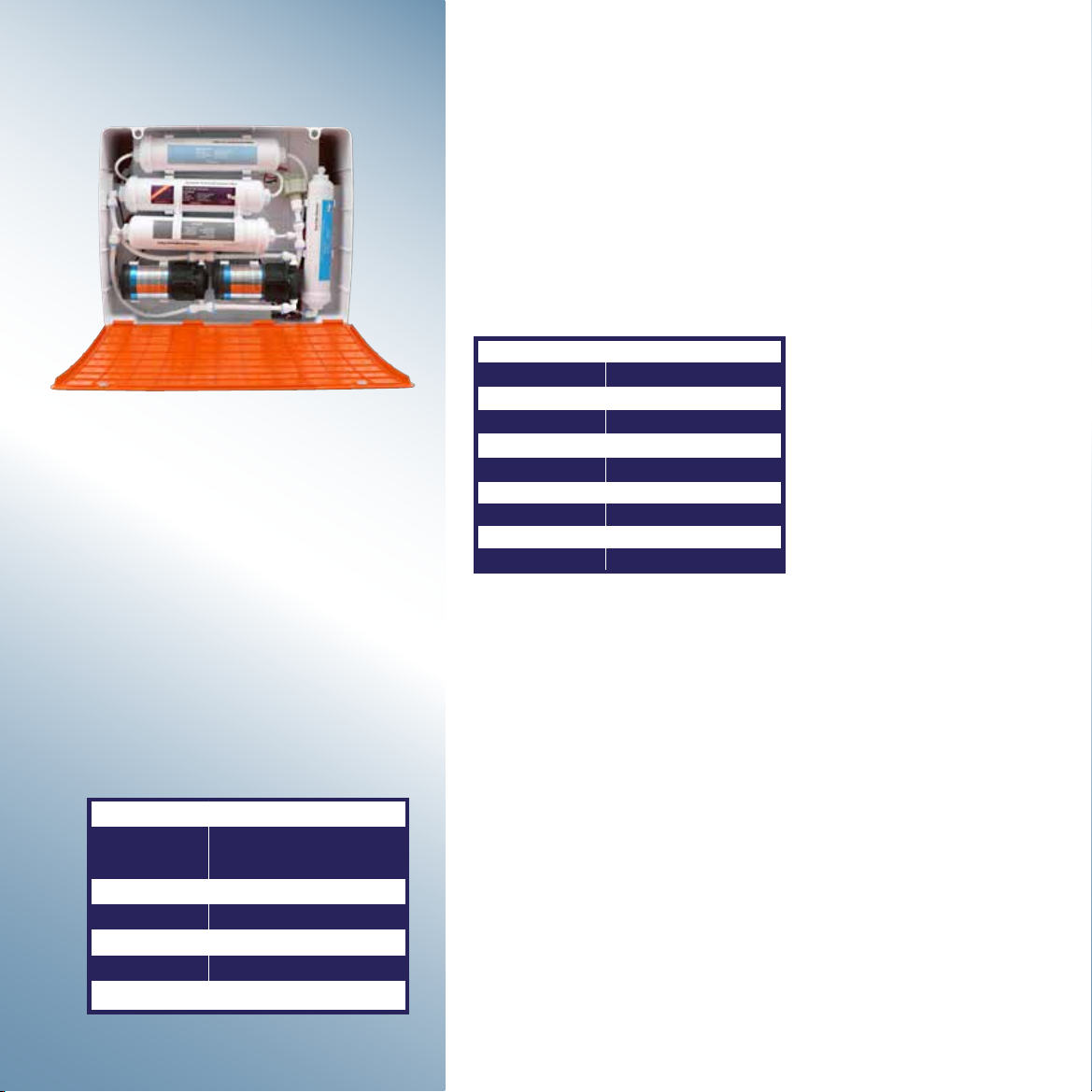
Technical Specifications
DAILY CAPACITY
PURIFICATION RATE
EFFICIENCY RATIO
RECOVERY RATING
PUMP FLOW RATE
PUMP PRESSURE
POWER SUPPLY PUMP
PRODUCT SIZE
BOX SIZE
GROSS WEIGHT
330 gpd (1.250 L/day)
%85-%98
% 4134,89%
% 45
3,2 L/min.
110 psi-150 psi (758-1.034 kPa)
24 V DC, 4A
374x452x207 mm
395x585x215 mm
11 kg
This appliance is used to obtain drinking water
from the mains water that have passed through
the municipal treatment processes. This water
should be microbiologically safe, subjected to the
necessary disinfection. If the parameters of the
inlet water are within the following ranges efficient
operation of the appliance is ensured. Systems
designed differently for waters such as sea water,
well water, muddy water etc. with a very high TDS
value are also available.
Fields of use
INLET WATER FEATURES
TEMPERATURE
OPERATING
RESSURE
pH RANGE
MAXIMUM FE
MAXIMUM TDS
TURBIDITY
HARDNESS
5 ˚C - 38 ˚C / (38 ˚F - 100 ˚F)
40 psi-145 psi / (2,8 bar-10 bar) /
(275 kPa - 1.000 kPa)
3-11
0,2 (ppm=mg/L)
1.250 (ppm=mg/L)
5 NTU
17 ˚Fr-10 ˚dH - 170 mg/L CaCO3
• Do not use this system with any water that is microbiologically unsafe, that does
not have adequate disinfection before or after operation or that of the quality is
unknown.
• Cebilon I’flow contains critical components that are required to be replaced
periodically to purify the total dissolved solid materials (TDS) efficiently. To check
the efficiency of the system, water from the appliance must be periodically tested.

4
Low Pressure Switch, if the water is cut or if the
pressure is lower than 0.2 bar (3 psi), it prevents
unnecessary operation of the pump.
5M Sediment Filter, it retains the substances and
particles floating in water to make the water clear.
Pressure Pump, brings the pressure of the water
from the pre-filtration to the level required for the
operation of the membrane.
Carbon Filter, retains free chlorine, organic
substances and unpleasant odors.
1M Sediment Filter / Carbon Filter, it retains the
substances and particles floating in water to make
the water clear.
Mineralized Post Carbon Filter provides mineral
to the clean water collected directly from the
membrane before if flows from the faucet, enriches
the water and regulates the pH. THROTTLE ensures
formation of required pressure in the membrane
by restricting flow so that the membrane can
perform the separation process. It is located on the
line where the waste water is drained.
Clean Water Faucet is where clean water is taken.
Pump Adapter is the power supply of the pump, it
converts the mains voltage to 24 V DC.
Water Leakage Shut off Closes the water inlet
mechanically in case of water leakage.
Automatic shut-off Valve closed the inlet water to
the membranes when pumps stop
Membrane Filter is the place where the reverse
osmosis occurs. A long film made of a
semi-permeable material is wrapped onto a reel in
two layers. These two layers are merged together
with a separator between the edges of this film with
two layers and it is closed to water passage. It is like
a closed long narrow bag except its end wrapped
on the reel with rowed holes that is on the end
which allows clean water output only. This double
layer film is wrapped onto a reel. Through the
separator film placed between the windings, dirty
water reaches all surfaces of this bag, clean water
enters the bag under pressure and taken from the
outlet holes. While dirty water passes by the film
surfaces with a flow called cross-flow, a part of
water passes through the internal part of the film
as clean water.
High Pressure Switch is stops the pump when the
pessure of clean water line reaches 2,6bar (38 psi).
Parts and functions
Figure 2. RO System Diagram
Mains water
Waste water
6 4
55
8
9
9
10
12
14
11
Mains Water
Water with Sediment Eliminated
Water with Sediment and Chlorine Eliminated
RO-Water
Waste Water
1- Adapter
2- Water leakage shut off
3- Low pressure switch
4- 5M sediment filter
5- Pump (pressure pump)
6- Carbon (Granul Active Carbon) filter
7- 1M sediment filter
8- Automatic shut-off valve
9- Membrane filter (100 GPD)
10- Membrane filter (130 GPD)
11- Flow restrictor
12- Mineralized post carbon filter
13- High pressure switch
14- Clean water faucet
1- 100 GPD Membran Filter
2- 100 GPD Membran Filter
3- 130 GPD Membran Filter
2
3
1
5
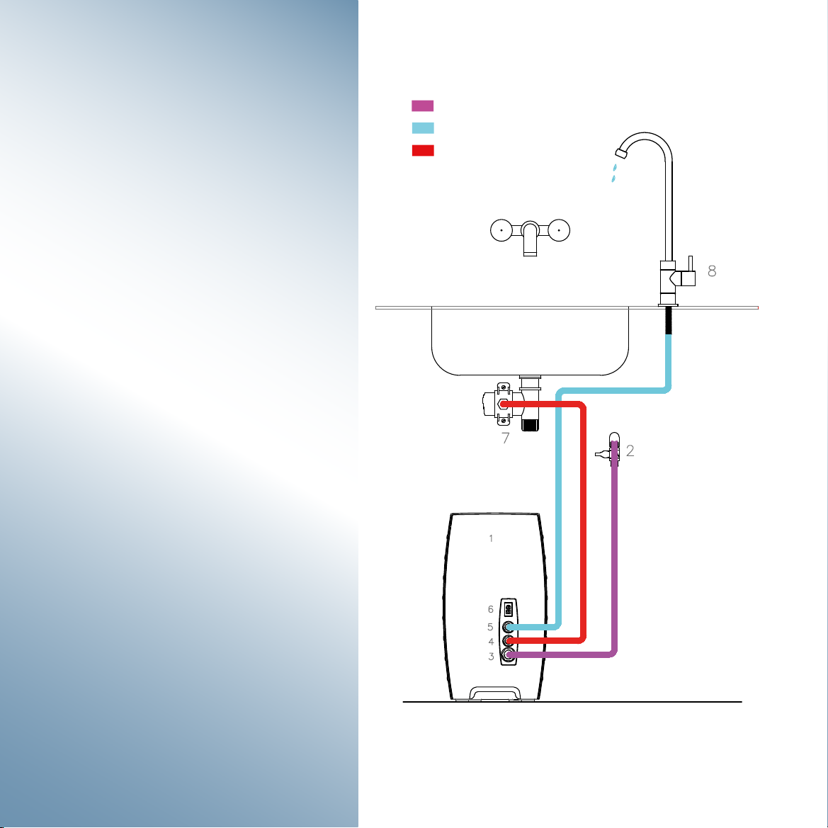
Installation
scheme
Please make sure that, flushing the filters, before you
start using the device. For filters flushing, you can follow
the instructions below.
!
WARNING
1- Measures should be taken against freezing.
2- Waste water should not interfered with.
3- When muddy (clay) water comes from the mains,
close the water inlet of theappliance.
4- If a water supply other than the mains will be used,
you must receive a drinking water report from relevant
institutions.
5- If it is a water source other than the mains water,
make sure that the disinfection process is performed.
6- Filters are considered as supplies and are outside
the scope of warranty.
7- Free chlorine in water may cause membrane filter in
the system to deteriorate.
Mains Water
RO-Water
Waste Water
1 Cebilon
2 Water Inlet Valve
3 Appliance Water Inlet
4 Waste Water Outlet
5 RO Water Outlet (Clean Water)
6 24 V Input
7 Waste Water Bracket
8 Clean Water Faucet
Figure 4. RO Installation Scheme
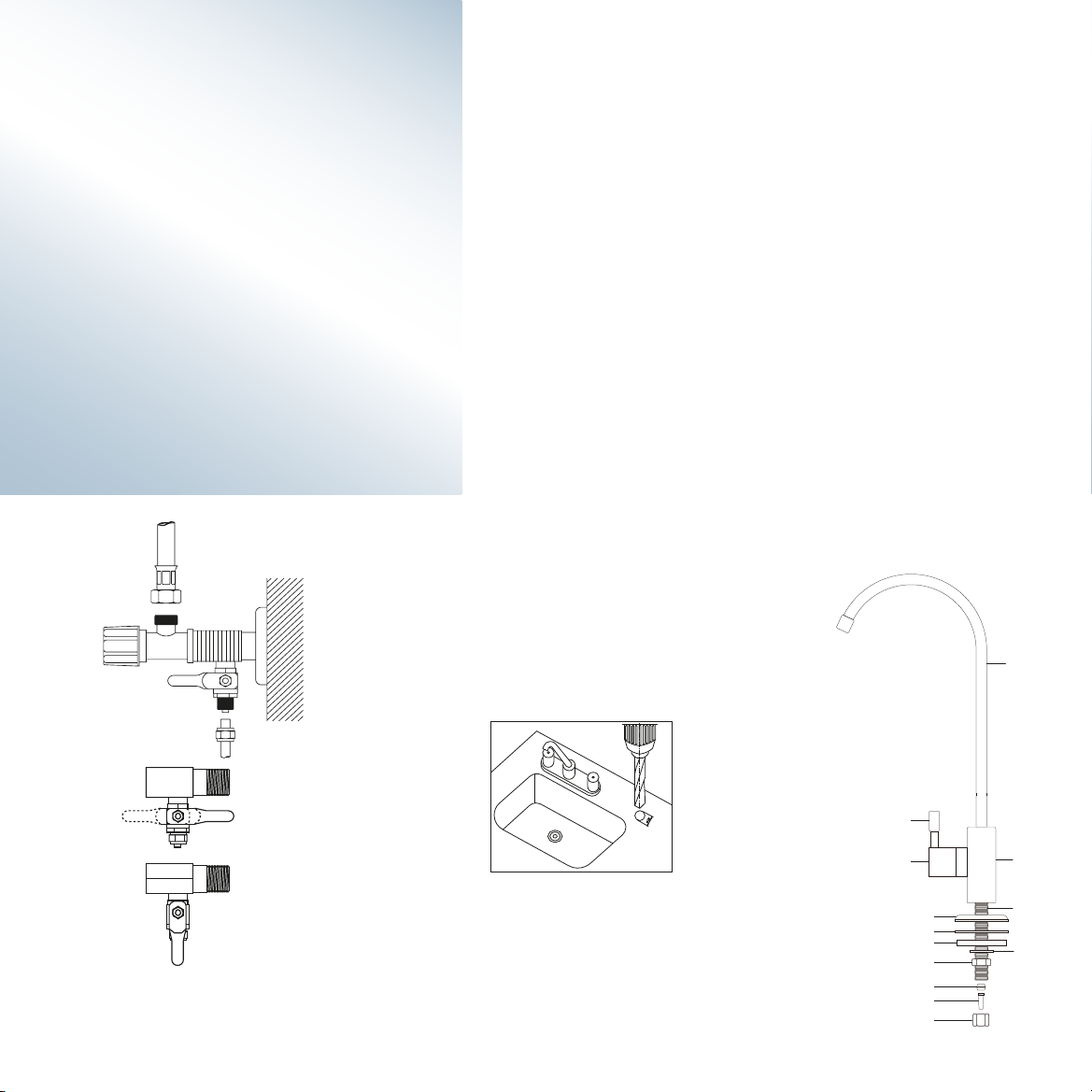
6
Installing the faucet
• Close the mains water from the apartment inlet valve.
• After draining the water left in the pipes from proper
places, mount the three-way adapter to the mains by
ensuring the sealing.
• First, mount the 1/4 ball valve to the three-way
adapter by wrapping a teflon tape in a position so that
the valve is opened and closed easily (Figure 5.a).
• Connect the water inlet hose to the ball valve (Figure 5.b).
• Make sure the ball valve is closed (Figure 5.c).
• Open the mains water, check whether there is any
leakage (Figure 5.d).
• Place the appliance on a suitable place underneath the
counter in upright position.
Clean water faucet should be mounted carefully in terms of use and aesthetics.
If the counter or kitchen sink will be drilled, drilling process should be proceed-
ed after the dimensions are obtained so as to install the washers, nuts and
unions under the counter or kitchen sink (Figure 6). Otherwise, drillingmay be
incorrect.
The location to be drilled may be granite, marble, concrete or stainless sink. If
the counter is granite, it must be drilled with a 20 mm diameter bore bit. Bore
bit is attached to the end of the drill and it is set to low speed. Water is poured
on the ground to be drilled (do not drill without water). Bend the bore bit as 45
degrees and press slightly, it makes a trail on the granite. Then it is brought to
an upright position slowly without lifting. When it reaches the upright position,
drilling iscompleted by applying enough force. If the bore bit is not kept
constant when we start drilling, parts can break off from the granite surface. The
o-ring on the faucet's mirror cannot ensure sealing and may cause the water
leakage down from the counter. Marble countertops can be drilled by the same
drilling bit or bore bit. Concrete countertops are drilled with a contact tip and
hammer drill. If concrete is coated with tiles, a pre drill is made
with a small-diameter drill bit to avoid cracking the tiles.
Bore bit for the stainless sinks is different.
Water Connection
d
b
c
a
Figure 5. Water connection fittings
Figure 6. Faucet
1 - Faucet Pipe
2- Faucet body
3- Handle
4- Hub cover
5- Faucet screw
6- Escutcheon plate
7- Tap oring
8- Bottom oring
9- Mounting washer
10- Compression nut
11- 1/4” ferrule
12- 1/4” Insert
13- Compression nut
1
2
5
6
7
89
10
11
12
13
3
4

7
Waste water
connection
Pre-tests
• The appliance is designed for domestic use.
Parts such as storage tank, waste water hose,
faucet must be attached indoor environment.
Necessary measures should be taken to prevent
freezing and waste water flow.
• Use the appliance after the necessary measures
are taken in microbiologically unsafe or
disinfected waters.
• The appliance must be supplied with its own
power adapter.
• If the appliance will not be used for a long time
(such as more than 1 month), the inlet water
valve must be closed (figure 9), the adapter
should be plugged out and the authorizes service
must be called to disinfect the appliance when
reactivating.
• When there not anyone in the house, close the
water inlet valve of the appliance for safety
purposes (Figure 8).
• The appliance must not be interfered for repair
and maintenance purposes. Otherwise, it falls out
of the warranty scope, these operations are
carried out by Cebilon Authorized Service.
• As the inlet water temperature changes, the
amount of clean water to be received and the
efficiency may change. Therefore, water obtained
may be low in winter and high in summer.
• In any unfavorableness (Figure 8) close the
water inlet valve and consult Cebilon Authorized
Service.
• The adapter is plugged in after it is placed
into the place where "24 V DC" is written on
the appliance. In this case, it will not work
due to lack of water and pressure in the
system.
• Clean water faucet is turned on.
• Mains water is supplied to the system by
opening the 3/8 ball valve (Figure 8). It is
seen that the pump is running.
• The faucet is closed after a small amount
of water flows from the clean water faucet.
• After the operation of the pump stops,
leak test of all the connections in the
system is performed.
• This system should be used after the
twenty-four hours washing process,
(Installation is done after this process is
carried out by an authorized service.)
• If waste water pipe of the sink is not a
throat hose but a 40 mm plastic pipe, it
is mounted in a 3/8" clamp sealing
sponge affixed state (Figure 7a).
• The flush is drilled from the hole of the
clamp in 8 mm diameter on the same
axis (Figure 7b). One end of the 3/8"
waste water faucet is connected to this
clamp and the other end is connected to
the 3/8" waste water union.
• If waste water hose will be mounted on
the 50 waste water installation, a 3/8"
clamp will be mounted and the waste
water hose will be mounted on its
location above this. A seal must be used
when mounting the adapter to the waste
water installation.
Points for
Attention
a
b
Figure 8. Mains inlet valveFigure 7. Waste water connection
MANUFACTURER : İHLAS EV ALETLERİ İMALAT
COMPANY SANAYİ VE TİCARET A.Ş.
BOSB Mermerciler Sanayi Sitesi, 7.Cd, No:14,
34524, Beylikdüzü, İstanbul / TURKEY
Phone : +90 212 875 3562
Faks : +90 212 875 3664
Model No : 101 - IFL
Cebilon i’flow Reverse Osmosis System
Have timely periodic maintenance of your appliance to use your
system efficiently and for longer time. The following replacement
periods are the recommended durations for appliances used in
mains water under normal conditions. The usage condition of your
appliance may change depending on the properties of inlet water,
amount of chlorine and sediment.
Our authorized services will perform periodic maintenance
required for your system to work efficiently every six months.
Recommended Filter Replacement Periods
Filter Name
Part Code
5 Micron Sediment Filter 350010Z 6 mounts
Carbon Filter 350002Z 6-12 mounts
1 Micron Sediment Filter 350003Z 6-12 mounts
Mineralized Post Carbon Filter 340005Z 6-12 mounts
Blue Membrane 100 GPD 349004Z 3 years
Blue Membrane 100 GPD 349004Z 3 years
Red Membrane 130 GPD 331014Z 4 years
This is where Reverse Osmosis occurs. Life of the filter will change depending on the ion concentration in the mains water, amount
of the distilled water and whether the maintenance is carried out in a timely manner.
Duties
Replacement
Period
Sediment filtration is performed by taking coarse particles in water. Clears the water at a micron level. Its life varies depending on
the nature of the inlet water.
This filtration is performed by taking coarse particles in water. Clears the water at a micron level. Its life varies depending on the
nature of the inlet water.
Keeps all the gas in water chemically in itself. The excess chlorine reduces the life of the carbon filter. Timely replacement protects
from damage of chlorine and extends the life of the membrane filter.
Regulates the pH by supplying mineral to water. Filters bad oders that may have been left in the water.
!
The ball valve in the appliance is closed before the filter
replacement. The pressure in the system is removed by opening
the faucet of the appliance sand. Filter replacement is carried.
After the filter replacement process is finished, the ball valve is
opened. Turn off the tap when water starts to flow from the tap.
Filter must not be replaced when inlet water is open and without
removing the pressure in the appliance.
WARNING
Maintenance of your appliance must be performed by an
Authorized Service, appliances that of the maintenance is not
performed by an Authorized Service will fall out of warranty.
The life of the filters used in Cebilon I’flow Reverse Osmosis
System changes depending on various factors with the amount
of water used. These major factors are inlet water quality,
chlorine amount, residue amount etc. Filters are considered as
supplies and they are out of warranty.
Maintenance
8

9
Troubleshooting
Foam in water or
milky coloured
water.
Low water from the
appliance.
The pump is running
continuously.
Air in the system.
Pump is not operating and there is
no sufficient pressure.
There is bending, crushing on the
hoses.
Pre-filter group is clogged.
Membrane does not perform well.
Inlet water temperature dropped.
Check valve is defective.
High Pressure Switch may be defective.
Low Pressure Switch may be defective.
Check valve may be defective.
Shut off valve may be defective.
Pump may be defective.
Air in the system is a normal occurrence after
initial installation. Sometimes, air caused by
the mains may exist. This will return to
normal after usage for a while. There is no
inconveniency for using this water.
Check whether the pump adaptor is
plugged in. If adaptor is plugged in, consult
to your service.
Check all the hoses connected to the
appliance, eliminate bendings, if any.
Please consult the service.
Please consult the service.
This is not a fault. Decrease in clean
water is normal during winter.
Please consult the service.
Close the inlet water and consult to your service.
Close the inlet water and consult to your service.
Please consult the service.
PROBLEM POSSIBLE CAUSES RECOMMENDED SOLUTION

10
DIGITAL SCREEN FUNCTIONS
Press and hold the ON/OFF button for 3 seconds to switch the device On/Off.
Each light indicates the service life of the respective filter.
GREEN LIGHT illuminates continuously under normal operating conditions.
RED LIGHT indicates that it is time to replace the 5 Micron Sediment,
Activated Carbon, 1 Micron Sediment and Post Carbon filters.
BLUE LIGHT (MEMBRANE) indicates that it is time to replace two 100 GPD
membrane filters.
RED LIGHT (MEMBRANE) indicates that it is time to replace 130 GPD
membrane filter.

Complies with WEEE Regulation
This symbol on the product or packaging shows that the product should not be disposed of with
normal domestic waste and should be transmitted to the collection points for recycling the
electrical and electronic appliances. If you dispose of this product correctly, you will be contributing
to the protection of the nature and human health. Wrong disposal will be harmful to the nature and
human health. You may find further information on recycling this product from your municipal,
waste collection service or from the store you have purchased the appliance.

BOSB Mermerciler San. Sitesi
7. Cad. No: 14 Beylikdüzü - İstanbul
Tel: 0212 875 35 62 Faks: 0212 875 36 64
338001Z
P.D. 2020.02.11
Table of contents
Popular Laboratory Equipment manuals by other brands


Analytik Jena
Analytik Jena qTOWER3 operating manual

Keysight
Keysight E6640A Getting started guide

Thermo IEC
Thermo IEC Medilite 6 Place Operation manual

Bibby Sterilin
Bibby Sterilin Techne No ICE Operator's manual

AVL DITEST
AVL DITEST IRP 120 user manual

WLD-TEC
WLD-TEC gasprofi1 micro operating instructions