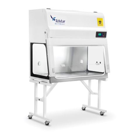
Telstar Bio II Advance Plus User manual

SM-BioIIAdvancePlus-EN-1812 1 / 40
SERVICE MANUAL
Microbiological Safety Cabinet
Bio II Advance Plus
In order to carry out the service tasks properly, it is required to check the User’s Manual together with
this manual.

SM-BioIIAdvancePlus-EN-1812 2 / 40

SM-BioIIAdvancePlus-EN-1812 3 / 40
INDEX
0.
COM ONENTS DESCRI TION ________________________________________ 4
1.
ELEMENTS LOCATION ______________________________________________ 6
2.
RE LACEMENT OF ELECTRICAL ELEMENTS ______________________________ 7
2.1.
Fuse of the power socket _______________________________________ 7
2.2.
C U card ____________________________________________________ 8
2.2.1.
Test and replacement of the C U fuses ________________________ 9
2.3.
Control panel (Display) _________________________________________ 10
2.4.
ower source ________________________________________________ 11
2.5.
Replacement of the Led lights ___________________________________ 12
2.6.
Replacement of the UV light _____________________________________ 13
2.7.
Replacement of the micro-switches _______________________________ 14
2.8.
Replacement of the speed probe _________________________________ 17
3.
RE LACEMENT OF MECHANICAL ELEMENTS _____________________________ 19
3.1.
Replacement of the Extraction Filter _______________________________ 20
3.2.
Replacement of the Impulsion Filter _______________________________ 21
3.3.
Replacement of the frontal glass _________________________________ 22
3.4.
Replacement of the gas springs of the glass ________________________ 24
4.
FUNCTIONAL TEST ________________________________________________ 25
5.
O ERATION AND CONTROL OF THE CABINET ___________________________ 26
5.1.
Start up of the cabinet _________________________________________ 26
5.2.
Alarms _____________________________________________________ 27
5.3.
User screens to be used in maintenance operations ___________________ 28
5.4.
Control functions with Technical Service assword ____________________ 30
5.5.
Calibration of the cabinet _______________________________________ 37
6.
RECOMMENDED INSTALLATION TEST _________________________________ 39
6.1.
Downflow Filters Integrity Test ___________________________________ 39
6.2.
Exhaust Filters Integrity Test ____________________________________ 39
6.3.
Downflow Air Velocity Test ______________________________________ 39
6.4.
Set oints Alarm Downflow Air Velocity Test ________________________ 39
6.5.
Inflow Air Velocity Test _________________________________________ 39
6.6.
Set oint Alarm Inflow Air Velocity Test ____________________________ 39
6.7.
Smoke Test __________________________________________________ 39
6.8.
Lighting Test _________________________________________________ 39
6.9.
Acoustic Level Test ____________________________________________ 39
7.
ELECTRICAL DIAGRAMS ____________________________________________ 39
8.
COM ONENTS ____________________________________________________ 39
8.1.
Optional Components __________________________________________ 39
9.
CLEANING _______________________________________________________ 40
9.1.
Superficial Cleaning ___________________________________________ 40
9.2.
Front Glass Disinfection and Cleaning ______________________________ 40
9.3.
Formol disinfection ____________________________________________ 40
9.4.
Disinfection with vaporized hydrogen peroxide ______________________ 40
10.
CERTIFICATES ___________________________________________________ 40

SM-BioIIAdvancePlus-EN-1812 4 / 40
0. COMPONENTS DESCRIPTION
Advance 4
1. Centrifugal Blower
2. Exhaust flexible tube
3. Laminar flow chamber or plenum
4. Laminar flow HE A filter
5. Exhaust HE A filter
6. Working area
7. Outside air inlet and protection barrier
8. Exhaust outlet

SM-BioIIAdvancePlus-EN-1812 5 / 40
Advance
1. Centrifugal Blower
2. Exhaust flexible tube
3. Laminar flow chamber or plenum
4. Laminar flow HE A filter
5. Exhaust HE A filter
6. Working area
7. Outside air inlet and protection barrier
8. Exhaust outlet

SM-BioIIAdvancePlus-EN-1812 / 40
1. ELEMENTS LOCATION
1 Exhaust outlet. Checking valve for D.O. . control
(Differential pressure).
2 ower supply. 7 Gas and vacuum connections
(O TIONAL).
3 Display and control panel.
4 C U card.
5 Checking valve fans pressure.

SM-BioIIAdvancePlus-EN-1812 7 / 40
2. REPLACEMENT OF ELECTRICAL ELEMENTS
WARNING
Before any service task ensure to perform a proper decontamination of the cabinet when
applicable as shown in user manual Annexes 5.3 and 5.4.
After finishing any service task, it must be ensured that the cabinet is working properly,
according the checklist shown in chapter 4.
WARNING
Before performing the following service tasks, unplug the power plug of the cabinet in order
to avoid any risk of electrical shock.
It must be ensured the right fixing of the frontal cover by means of the two roods that are
supplied for such purpose.
REMARK
When it is required for the specific service task, the frontal cover must be raised or put back
to the closed position only when the glass is in the closed position. The contacts of the
frontal cover must be pushed back manually.
REMARK
Only use original spare parts from the manufacturer.
2.1. FUSE OF THE POWER SOCKET
The main power socket has inside protection fuses.
In order to replace these fuses it is necessary to open the cover where they are located, take
the fuses out and replace them by new ones that fulfill the following features:
T10A 250V 5x20mm.

SM-BioIIAdvancePlus-EN-1812 8 / 40
2.2. CPU CARD
For the replacement of the C U card, these steps should be followed:
a) Unplug the cord plug of the cabinet.
b) Remove the two M5 screws that hold the frontal cover and lift it up, fixing it with the two
rods provided for that objective. (Fig.1)
c) Disconnect all C U card connectors (Fig.2)
d) Unscrew the M4 central screw and its washer (Fig.3)
e) Remove the four fixing screws and take out carefully the C U card (Fig.4)
For the installation of the new C U card, all steps should be carried out in reverse order,
reminding to connect the central grounding with its washer (Fig.3), and screwing the two M5
screws that fix the frontal cover. By replacing the chip (Fig.5) of the new card by the old one
the calibration data are maintained. Otherwise it is necessary to re-calibrate the cabinet.
Fig. 1 Fig. 2
Fig. 3 Fig. 4
Fig. 5

SM-BioIIAdvancePlus-EN-1812 9 / 40
2.2.1. TEST AND REPLACEMENT OF THE CPU FUSES
The C U card includes 5 fused for the lighting, sockets of the chamber and the fans.
In order to replace the fuses it is required to turn 180º the cover of the specific fuse holder,
take the fuse out and replace it by a new one that fulfills the following features:
F1 – CPU-Karte 8A 250V
F2 – Fan fuse 10A 250V
F3 – (not used for Advance)
F4 – Sockets fuse 5A 250V
F5 – Light fuse 1. A 250V
F – UV Light fuse 1A 250V
F2
F1
F
F
5
F
4
F
3

SM-BioIIAdvancePlus-EN-1812 10 / 40
2.3. CONTROL PANEL (DISPLAY)
For the replacement of the Control panel (display), these steps should be followed:
a) Unplug the cord plug of the cabinet.
b) Remove the two M5 screws that hold the frontal cover and lift it up, fixing it with the two
rods provided for that objective (Fig.1)
c) Disconnect the connector of the display card (Fig.2)
d) Unscrew the six M3 screws and its washers (Fig.3)
e) Take out carefully the display card.
For the installation of the new display, all steps should be carried out in reverse order,
reminding to screw the two M5 screws that fix the frontal cover.
Fig. 1 Fig. 2
Fig. 3

SM-BioIIAdvancePlus-EN-1812 11 / 40
2.4. POWER SOURCE
For the replacement of the power source, these steps should be followed:
a) Unplug the cord plug of the cabinet.
b) Remove the two M5 screws that hold the frontal cover and lift it up, fixing it with the two
rods provided for that objective. At that point you can see the power source (Fig.1 & 2)
c) Disconnect all connectors of the power source (Fig.3)
d) Remove the six M4 screws that fix the electronics support (Fig.4)
e) Remove the three M3 screws that fix, by the lateral, the power source (Fig.5)
f) Take out carefully the power source.
For the installation of the new power source, all steps should be carried out in reverse order,
reminding to screw the two M5 screws that fix the frontal cover.
Fig. 1 Fig. 2
Fig. 3 Fig. 4
Fig. 5

SM-BioIIAdvancePlus-EN-1812 12 / 40
2.5. REPLACEMENT OF THE LED LIGHTS
For the replacement of the led lights, these steps should be followed:
a) Unplug the cord plug of the cabinet.
b) Take out the two M5 screws of the frontal cover of the lighting fitting (Fig.1).
c) Lift the led lighting fitting and pull carefully the led light downwards in order it is unclipped
(Fig.2).
For the installation of the new led light, all steps should be carried out in reverse order,
reminding to screw the two M5 screws that fix the frontal cover.
Fig.1
Fig.2a (view from below after lifting the cover)
Fig.2b

SM-BioIIAdvancePlus-EN-1812 13 / 40
2.6. REPLACEMENT OF THE U LIGHT
For the replacement of the UV light, these steps should be followed:
a) Unplug the cord plug of the cabinet.
b) Detach the frontal-glass from the cabinet (by pulling from the lateral handles of the
metal support (Fig.1), and move the glass to the limit upper position.
c) Take out the UV light from the lamp holders by rotating and pulling down the tube.
(Fig.2).
d) Assemble the new tube in the lamp-holders, by fully pulling up the tube on the slot of the
lamp-holders, and then rotating it.
Fig.1
Fig.2

SM-BioIIAdvancePlus-EN-1812 14 / 40
2.7. REPLACEMENT OF THE MICRO-SWITCHES
For the replacement of the micro-switches and/or the glass working position actuator, these
steps should be followed:
a) Unplug the cord plug of the cabinet.
b) Remove the two M5 screws that hold the frontal cover and lift it up, fixing it with the two
rods provided for that objective (Fig.1)
c) For the replacement of one of the micros, take out the connectors and the two M3 nuts of
each micro (Fig.2)
d) For the replacement of the actuator sheet, take out the four M3 nuts that fix the micros
and the actuator sheet (Fig.2)
e) For the installation of the new micros or actuator sheet, all steps should be followed in
reverse order, adjusting the actuator position with the nuts M4 (Fig.3) and checking that the
4 plastic spacing parts are below the micros (Fig. 4)
f) To check that they are well adjusted, put the cabinet and the glass in working position,
checking that the actuator sheet pushes both micros.
Fig. 1 Fig. 2
Fig. 3 Fig. 4

SM-BioIIAdvancePlus-EN-1812 15 / 40
For replacing the glass closed position micro-switches, these steps should be followed:
a) Unplug the cord plug of the cabinet.
b) Detach the frontal mechanism from the cabinet. That way it will be possible to access the
micro-switches (Fig.1) that are located at the right side of the cabinet.
c) Take out the two M3 nuts of the micro to be replaced (Fig.2)
d) Loose the opposite end of the cabling, that is screwed to the inferior part of the right
contact between the frontal cover and the frontal mechanism.
e) For the installation of the new micros or actuator, all steps should be carried out in
reverse order, and welding previously the micro to the cabling (Fig.2 & 3) and adjusting the
position in order that the micros actuate correctly with the actuator (Fig. 2 & 4).
Fig. 1 Fig. 2
Fig.3
Fig. 4

SM-BioIIAdvancePlus-EN-1812 1 / 40
For replacing the contacts between the frontal cover and the frontal mechanism, these steps
should be followed:
a) Unplug the cord plug of the cabinet.
Upper part of the contacts:
b) Remove the two M5 screws that hold the frontal cover and lift it up, fixing it with the two
rods provided for that objective (Fig.1)
c) The contacts are screwed to the frontal cover with two nuts, that should be unscrewed, as
well as the terminals of the cabling that get to the contacts (Fig.2)
Lower part of the contacts:
d) Detach the frontal mechanism from the cabinet. The contacts can then be accessed
(Fig.3) at the right side of the cabinet.
e) Release the opposite end of the cabling, that is screwed to the lower part of the contacts
between the frontal cover and the frontal mechanism, and remove the two nuts.
For the installation of the new contacts, all steps should be carried out in reverse order,
adjusting and checking the correct alignment between both upper and lower parts of the
contacts (Fig.4)
Fig. 1 Fig. 2
Fig.3
Fig.4

SM-BioIIAdvancePlus-EN-1812 17 / 40
2.8. REPLACEMENT OF THE SPEED PROBE
WARNING
Before replacing the speed probe, ensure that the fans are fully stopped.
For the replacement of the speed probe, these steps should be followed:
a) Unplug the cord plug of the cabinet.
b) Remove the two M5 screws that hold the frontal cover and lift it up, fixing it with the two
rods provided for that objective (Fig.1)
c) Remove all screws M5 that hold the frontal cover of the plenum (Fig.2) and remove it.
The plenum can then be accessed, where the speed probe is located (Fig.3)
d) According Fig.9, loose the nut of the support of the speed probe until it can be released.
For totally removing this nut, it is necessary to take out first the extraction filter (Fig.4)
in order to access to the countersunk (Fig.5)
Disconnect the connector of the C U (Fig.8)
e) Carry out the change.
For the installation of the new speed probe, all steps should be carried out in reverse order,
taking into account to place the speed probe with its holes in vertical position and the flag
of the speed probe must be looking upwards, because the flow should go through it
(Fig.6). The distance that should remain between the end of the probe and the sheet should
be 120 mm (Fig.7).
As last step, it is necessary to check the correct calibration of the cabinet.
Fig. 1 Fig. 2
Fig. 3 Fig. 4

SM-BioIIAdvancePlus-EN-1812 18 / 40
Fig. 5 Fig.
Fig. 7 Fig. 8
Fig. 9

SM-BioIIAdvancePlus-EN-1812 19 / 40
3. REPLACEMENT OF MECHANICAL ELEMENTS
WARNING
Before any service task ensure to perform a proper decontamination of the cabinet when
applicable as shown in user manual Annexes 5.3 and 5.4.
After finishing any service task, it must be ensured that the cabinet is working properly,
according the checklist shown in chapter 4.
WARNING
Before performing the following service tasks, unplug the power plug of the cabinet in order
to avoid any risk of electrical shock.
It must be ensured the right fixing of the frontal cover by means of the two roods that are
supplied for such purpose.
REMARK
When it is required for the specific service task, the frontal cover must be raised or put back
to the closed position only when the glass is in the closed position. The contacts of the
frontal cover must be pushed back manually.
REMARK
Only use original spare parts from the manufacturer.

SM-BioIIAdvancePlus-EN-1812 20 / 40
3.1. REPLACEMENT OF THE EXTRACTION FILTER
WARNING
Before proceeding to replace the filters, ensure that the fans are fully stopped.
For the replacement of the extraction filter, these steps should be followed:
a) Remove the two M5 screws that hold the frontal cover and lift it up, fixing it with the two
rods provided for that objective (Fig.1)
b) Remove all M5 screws that hold the frontal cover of the plenum (Fig.2) and remove it.
The plenum can then be accessed, where the filters are located.
c) Operate the two clamps (left and right) that hold the extraction filter (Figs.3&4), by
pushing or pulling the red levers they have.
d) Take out the filter by the frontal part (Fig.5).
For the installation of the new filter, all steps should be carried out in reverse order, checking
that it is perfectly supported all along the upper and the lower gaskets. As last step it is
necessary to re-calibrate the cabinet.
Fig. 1 Fig. 2
Fig. 3 Fig. 4
Fig. 5
Other manuals for Bio II Advance Plus
1
Table of contents
Other Telstar Laboratory Equipment manuals