Ihse Draco 238 Series User manual

IHSE GmbH Maybachstraße 11 88094 Oberteuringen Germany
Draco Converter
238 Series
Media / DVI Converter
User Manual
Edition: 2021-10-14

Media / DVI Converter
2 2021-10-14
Copyright
© 2021. All rights reserved. This information may not be reproduced in any
manner without the prior written consent of the manufacturer.
Information in this document is subject to change without notice.
Trademarks
All trademark and trade names mentioned in this document are
acknowledged to be the property of their respective owners.

Contents
2021-10-14 3
Contents
1 About This Manual ....................................................................... 6
1.1 Scope.................................................................................. 6
1.2 Validity ................................................................................ 6
1.3 Cautions and Notes ............................................................ 6
1.4 EU Declaration of Conformity.............................................. 6
2 Safety Instructions ....................................................................... 7
3 Description ................................................................................... 8
3.1 Application .......................................................................... 8
3.2 System Overview ................................................................ 9
3.3 Product Range .................................................................. 10
3.4 Upgrade Kits ..................................................................... 10
3.5 Accessories....................................................................... 11
3.6 Device Views .................................................................... 11
3.6.1 Model K238-5V ................................................... 11
3.6.2 Model K238-5VE................................................. 12
3.6.3 Model K238-5VS................................................. 13
3.6.4 Model K238-5FBNC............................................ 14
3.7 Status LEDs ...................................................................... 15
4 Installation .................................................................................. 16
4.1 Package Contents............................................................. 16
4.2 System Setup.................................................................... 17
4.3 Example Applications........................................................ 18
5 Configuration.............................................................................. 19
5.1 Infrared Remote Control.................................................... 19
5.2 Control via Keyboard......................................................... 22
5.3 On Screen Display (OSD) ................................................. 24
5.3.1 Main Menu Item 'Color Settings' ......................... 25
5.3.2 Main Menu Item 'Picture Settings'....................... 27
5.3.3 Main Menu Item 'Input Settings' .......................... 30
5.3.4 Main Menu Item 'Output Settings' ....................... 31

Media / DVI Converter
4 2021-10-14
5.3.5 Main Menu Item 'General Settings' ..................... 33
6 Operation .................................................................................... 37
6.1 Optimization of Picture Settings ........................................ 37
6.1.1 Optimization of Output Settings .......................... 37
6.1.2 Optimization of Input Settings ............................. 38
6.1.3 Optimization of Picture Settings .......................... 39
6.2 Download of DDC Information .......................................... 39
6.2.1 Download of DDC by Infrared Remote Control ... 40
6.2.2 Download of DDC via OSD ................................. 40
6.2.3 Further DDC settings .......................................... 40
6.3 Serial Interface.................................................................. 41
7 Specifications ............................................................................. 42
7.1 Interfaces .......................................................................... 42
7.1.1 DVI-D Single Link................................................ 42
7.1.2 DVI-I Single Link ................................................. 42
7.1.3 S-Video (Y/C)...................................................... 42
7.1.4 SDI Video............................................................ 42
7.1.5 EGA (D-Sub 9).................................................... 43
7.1.6 Composite Video (VBS / CVBS) ......................... 43
7.1.7 Component Video (YPbPr).................................. 43
7.1.8 RGB Video .......................................................... 43
7.2 Supported Video Modes.................................................... 44
7.3 Serial Control .................................................................... 52
7.3.1 Telegram Structure ............................................. 52
7.3.2 Examples ............................................................ 52
7.4 Connector Pinouts ............................................................ 53
7.5 Power Supply.................................................................... 56
7.6 Environmental Conditions ................................................. 56
7.7 Size................................................................................... 57
7.8 Shipping Weight................................................................ 57
8 Troubleshooting......................................................................... 58
8.1 Blank Screen..................................................................... 58

Contents
2021-10-14 5
8.2 Picture............................................................................... 59
8.3 General ............................................................................. 59
9 Technical Support ...................................................................... 60
9.1 Support Checklist.............................................................. 60
9.2 Shipping Checklist ............................................................ 60
10 Directives .................................................................................... 61
10.1 North American Regulatory Compliance ........................... 61
10.2 WEEE ............................................................................... 61
10.3 RoHS/RoHS 2................................................................... 61
11 Glossary...................................................................................... 62
Pos: 1 /806-IHSE/Zu di esem Handbuch/ATB_Zu di esem Handbuch @ 5\mod_12785731632 76_6.doc @ 41510 @ 1222 @ 1

Media / DVI Converter
6 2021-10-14
1 About This Manual
1.1 Scope
This manual describes how to install your Media / DVI Converter, how to
operate it and how to perform trouble shooting.
1.2 Validity
This manual is valid for all devices listed on the front page. The product
code is printed on the base of the devices.
1.3 Cautions and Notes
The following symbols are used in this manual:
This symbol i
ndicates an important operating instruction that should be
followed to avoid any potential damage to hardware or property, loss of
data, or personal injury.
This symbol indicates important information to help you make the best use
of this product.
This symbol indicates best practice information to show recommended
and optimal ways to use this product in an efficient way.
Pos: 2 /806-IHSE/Si cherheitshi nweise/ATB_Sicher heitshinweise @5\mod_1278573321245_6. doc @ 41528 @ 1 @ 1
1.4 EU Declaration of Conformity
Please find the EU Declaration of Conformity for the product series under:
www.ihse.com/eu-declaration-of-conformity
A copy of the original, product-specific EU Declaration of Conformity can
be provided upon request.

Safety Instructions
2021-10-14 7
2 Safety Instructions
To ensure reliable and safe long-term operation of your Media / DVI
Converter please note the following guidelines:
Installation
Only use in dry, indoor environments.
Only use the device according to this User Manual. Failure to follow
these procedures could result in damage to the equipment or injury to
the user or installer.
The Media / DVI Converter and the power supply units can get warm.
Do not install components in an enclosed space without any airflow.
Do not place the power supply directly on top of the device.
Do not obscure ventilation holes.
Only use power supplies originally supplied with the product or
manufacturer-approved replacements. Do not use a power supply if it
appears to be defective or has a damaged chassis.
Connect all power supplies to grounded outlets. In each case, ensure
that the ground connection is maintained from the outlet socket
through to the power supply's AC power input.
Do not connect the link interface to any other equipment, particularly
network or telecommunications equipment.
Take any required ESD precautions.
In order to disconnect the device completely f
rom the electric circuit, all
power cables have to be removed.
Repair
Do not attempt to open or repair a power supply unit.
Do not attempt to open or repair the Media / DVI Converter. There are
no user serviceable parts inside.
Please contact your dealer or manufacturer if there is a fault.
Pos: 3 /806-IHSE/Besc hreibung/UEB_Bes chreibung @ 5\mod_1278573379151_6. doc @ 41546 @ 1 @ 1

Media / DVI Converter
8 2021-10-14
3 Description
Pos: 4 /806-IHSE/Besc hreibung/Ver wendungszweck/ 238-5v-xx @ 5\mod_129113 2998828_6.doc @ 45123 @ 2 @ 1
3.1 Application
The Media / DVI Converter is used to convert and output video signals of
one or more video sources (computer, CPU, camera, DVD player) in DVI-
D format.
The Media / DVI Converter can be used as a switch between multiple
input signals.
The Media / DVI Converter can be used to scale video signals to a specific
output format.
Pos: 6 /806-IHSE/Beschr eibung/Verwendungs zweck/Info Wohnbereic h 480-xxC @ 25 \mod_1580969545392_6.doc @271750 @ @ 4
This
is a Class A product. In a domestic environment, this product may
cause radio interference in which case the user may be required to take
adequat
e measures.
The safety instructions an
d installation guidelines noted in this manual
shall
be considered in detail. Compliance with the specifications for cable
lengths and types is mandatory.
Pos: 5 /806-IHSE/Besc hreibung/Syst em-Übersicht /238-5v-xx @ 5\mod_1291133036 937_6.doc @ 45141 @ 2 @ 1

Description
2021-10-14 9
3.2 System Overview
The input ports of the Media / DVI Converter are connected to the video
source(s) (e.g. computer, CPU, camera, DVD player, SPS control), using
the cables supplied or other suitable video cables.
The DVI-D monitor is connected to the output.
System Overview
1 Sources (DVD player, computer, camera, SPS control)
2 Media / DVI Converter
3 Monitor
See Chapter
4.3, Page 18 for installation examples.
Pos: 6 /806-IHSE/Besc hreibung/Ger ätetypen/238-5v-xx @ 5\mod_1291 133064500_6.doc @ 45159 @ 2 @ 1

Media / DVI Converter
10 2021-10-14
3.3 Product Range
Model
Description
K238-5V Media / DVI Converter for VGA- / DVI-Input (up
to 1920x1200)
K238-5V-S Media / DVI Converter for VGA- / DVI-Input (up
to 1920x1200) and serial option
K238-5VE Media / DVI Converter for VGA- / DVI-Input (up
to 1920x1200) and Video (Y/C) / Component (YPbPr) /
CVBS and CGA / EGA / MDA
K238-5VE-S Media / DVI Converter for VGA- / DVI-Input (up
to 1920x1200) and Video (Y/C) / Component (YPbPr) /
CVBS and CGA / EGA / MDA and serial option
K238-5VS Media / DVI Converter for VGA- / DVI-Input (up
to 1920x1200) and Video (Y/C) / Component (YPbPr) /
CVBS and (HD-)SDI
K238-5VS-S Media / DVI Converter for VGA- / DVI-Input (up
to 1920x1200) and Video (Y/C) / Component (YPbPr) /
CVBS and (HD-)SDI and serial option
K238-5FBNC Media / DVI Converter for RGB- / VGA- / DVI-Input (up
to 1920x1200) with a separate 5x BNC RGB-Input
The input side of the following KVM extenders corresponds to the
Media /
DVI Converter
K238-5V: K477-xxxxV, L474-xxxxV.
Pos: 7 /806-IHSE/Besc hreibung/Ei nbauoptionen/238-5v-x x @ 5\mod_1291133125140_6.doc @45177 @ 2 @ 1
3.4 Upgrade Kits
Model Description
455-4G 19"/1U rack mount kit to mount up to 4 devices of type
K238-5V
474-VRMK 19"/1U rack mount kit to mount up to 3 devices of type
K238-5VE, -5VS or -5FBNC
455-1K Mounting plate to mount by screws
(type K238-5V)
455-2K Mounting plate to mount by snap on
(type K238-5V)
474-VPLATE Mounting plate to mount by snap on or screws (type
K238-5VE, -5VS or -5FBNC)
The
Media / DVI Converters and power supply units become warm and
must not be installed in closed rooms with no air circulation. For rack
-
mount installation
s, at least 0.5U (height unit) is required above the
extenders for ventilation.
Pos: 8 /806-IHSE/Besc hreibung/Zubehör /238-5v-xx @ 5\mod_1291133 182906_6.doc @ 45196 @ 2 @ 1
Description
2021-10-14 11
3.5 Accessories
Model Description
238-BCA Video adapter (BNC connector to Cinch connector)
238-BNC RGB cable (2.0 m, 5x BNC connector)
238-EGA EGA cable (1.8 m, D-Sub 9 connector)
238-IR Infrared remote control
238-RCA Component video cable (1.5 m, 3x RCA connector)
238-SDI SDI cable (1.8 m, BNC connector)
238-SV S-Video cable (3.0 m, Mini-DIN connector, 4 pole)
260-5U International power supply unit 100...240VAC / 5VDC / 4 A
436-AA VGA cable (1.8 m, VGA connector to DVI-I connector)
436-DB1 RGB / DVI cable (0.2 m, 5x BNC connector to DVI-D
connector)
436-ID DVI-D cable (1.8 m, DVI-D connector)
Pos: 9 /806-IHSE/Besc hreibung/G eräteansichten/ UEB_Geräteansic hten @ 5\mod_1278573737808_6.d oc @ 41654 @ 2 @ 1
3.6 Device Views
Pos: 10 /806-IHSE/ Beschreibung/Ger äteansichten/ 238-5v-xx/Typ K238-5V @ 5\mod_1291133242406_6.doc @45216 @ 3 @ 1
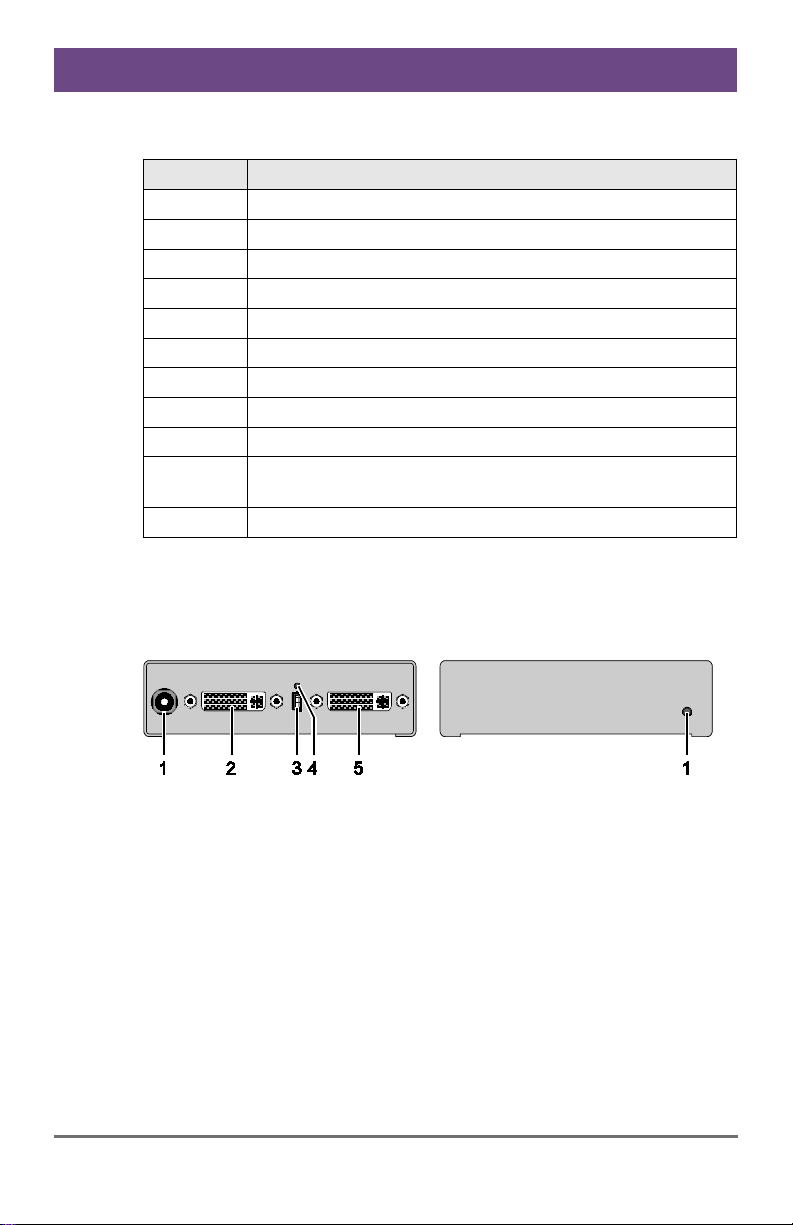
3.6.1 Model K238-5V
Rear View
Front View
1 Connect to 5VDC power
supply
2
Input: DVI-I (VGA)
3
Service port
4
IR receiver for remote control
5
Output: DVI-D
1 IR receiver for remote control
Pos: 11 /806-IHSE/ Beschreibung/Ger äteansichten/ 238-5v-xx/Typ K238-5VE @ 5\mod_12911332 93343_6.doc @ 45234 @ 3 @ 1
Neuedings kommt Windows-I nsta ller
Media / DVI Converter
12 2021-10-14
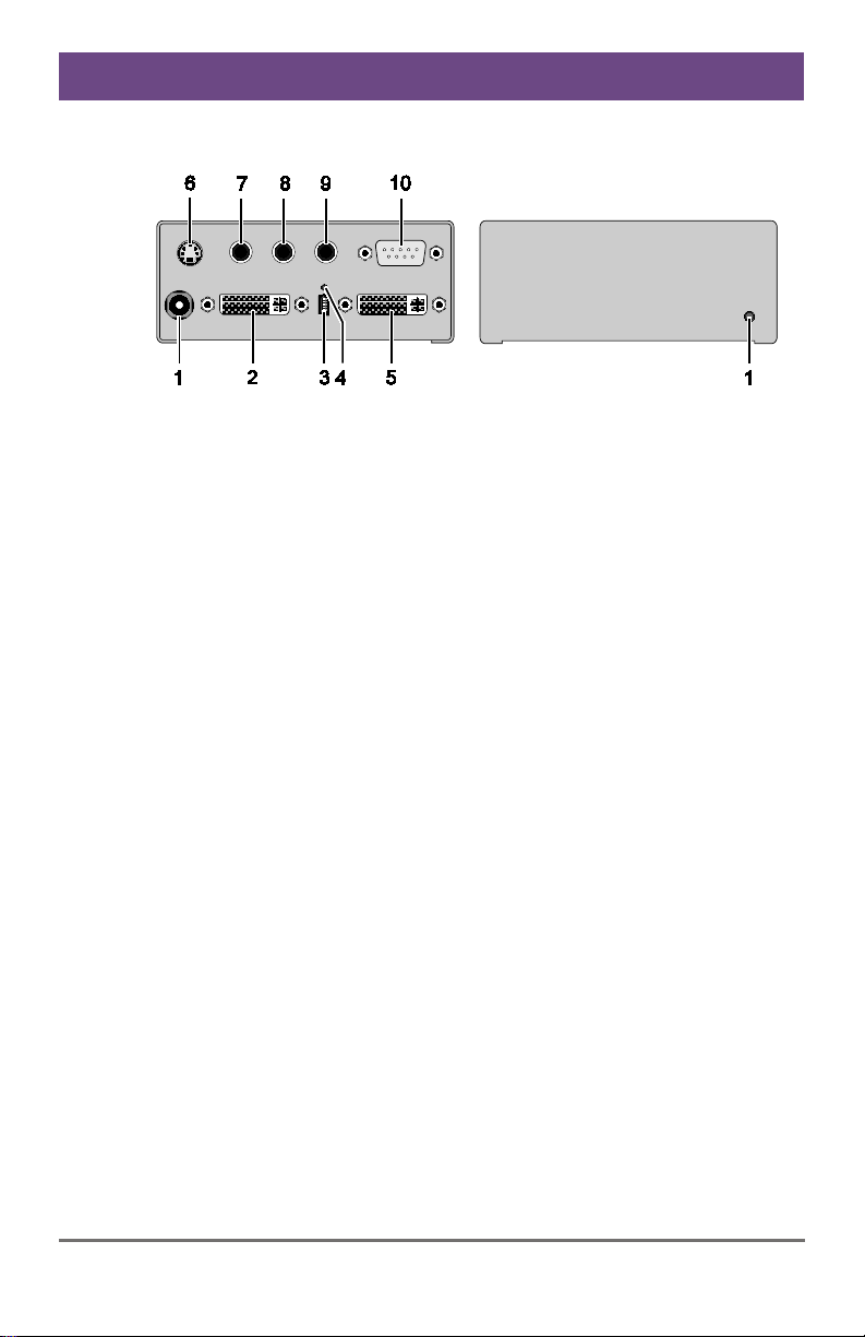
3.6.2 Model K238-5VE
Rear View
Front View
1 Connect to 5VDC power
supply
2
Input: DVI-I (VGA)
3
Service port
4
IR receiver for remote control
5
Output: DVI-D
6
Input: S-Video (Y/C)
7
Input: CVBS 1 or YPbPr (Pr)
8
Input: CVBS 2 or YPbPr (Y)
9
Input: CVBS 3 or YPbPr (Pb)
10
Input: EGA
1 IR receiver for remote control
Pos: 12 /806-IHSE/ Beschreibung/Ger äteansichten/ 238-5v-xx/Typ K238-5VS @ 5\mod_12911333 09656_6.doc @ 45253 @ 3 @ 1
Description
2021-10-14 13
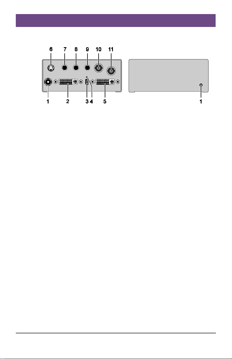
3.6.3 Model K238-5VS
Rear View
Front View
1 Connect to 5VDC power
supply
2
Input: DVI-I (VGA)
3
Service port
4
IR receiver for remote control
5
Output: DVI-D
6
Input: S-Video (Y/C)
7
Input: CVBS 1 or YPbPr (Pr)
8
Input: CVBS 2 or YPbPr (Y)
9
Input: CVBS 3 or YPbPr (Pb)
10
Input: CVBS 4
11
Input: (HD-)SDI
1 IR receiver for remote control
Pos: 13 /806-IHSE/ Beschreibung/Ger äteansichten/238-5v -xx/Typ K238-5FBNC @ 5\mod_129113333668 7_6.doc @ 45272 @ 3 @ 1

Media / DVI Converter
14 2021-10-14
3.6.4 Model K238-5FBNC
Rear View
Front View
1 Connect to 5VDC power
supply
2
Input: DVI-I (VGA)
3
Service port
4
IR receiver for remote control
5
Output: DVI-D
6
Input: RGB (red)
7
Input: RGB (green)
8
Input: RGB (blue)
9
Input: RGB (H-/Compos. Sync,
RGBs)
10
Input: RGB (V-Sync)
1 IR receiver for remote control
Pos: 14 /806-IHSE/ Beschreibung/Diagnos e LEDs/238-5v-xx @ 5\mod_1291133365 796_6.doc @ 45291 @ 2 @ 1
Description
2021-10-14 15
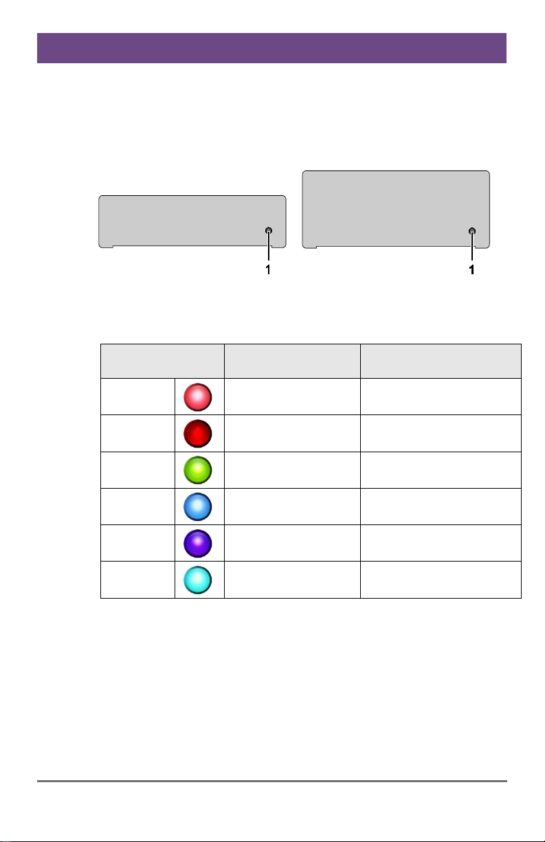
3.7 Status LEDs
The Media / DVI Converter is fitted with a multi-color LED to indicate
connection status:
K238
-5V K238-5VE / -VS / -FBNC
Front View
Front View
LED 1: Connection and Video Status
LED color Description for the
input
Description for the
output
Red
No input signal Monitor detected
Dark Red
Resolution not
supported
Monitor not detected
Green
Active video signal Monitor not detected
Blue
No input signal Monitor detected
Violet
Resolution not
supported
Monitor detected
Light blue
Active video signal Monitor detected
Pos: 15 /806-IHSE/I nstallation/ UEB_Installati on @ 5\mod_1278574971589 _6.doc @ 41768 @ 1 @ 1
Media / DVI Converter
16 2021-10-14
4 Installation
Pos: 16 /806-IHSE/Ins tallation/Lief erumfang prüfen/238-5v-xx @ 5\mod_1291133570 562_6.doc @ 45310 @ 2 @ 1
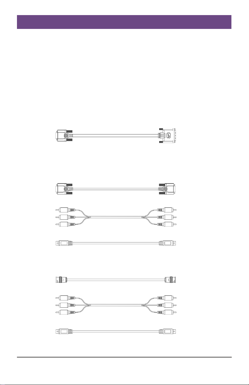
4.1 Package Contents
Your Media / DVI Converter package contains the following items:
Media / DVI Converter device
5VDC international power supply unit
Country-specific power cord
Quick Setup
VGA cable (1.8 m, VGA connector to DVI-I connector)
Infrared remote control
Additional content for K238-5VE:
EGA cable (1.8 m, D-Sub 9 connector)
Component video cable (1.5 m, 3x RCA connector)
S-Video (3.0 m, Mini-DIN connector, 4 pole)
Additional content for K238-5VS:
SDI cable (2.0 m, BNC connector)
Component video cable (1.5 m, 3x RCA connector)
S-Video (3.0 m, Mini-DIN connector, 4 pole)

Installation
2021-10-14 17
Additional content for K238-5FBNC:
RGB cable (2.0 m, 5x BNC connector).
If anything is missing, contact your dealer.
Pos: 17 /806-IHSE/I nstallation/System ansc hließen/238-5v-xx @ 5\mod_1291133 656078_6.doc @ 45329 @ 2 @ 1
4.2 System Setup
First
time users are recommended to setup the system with the CPU Unit
and the CON
Unit in the same room as a test setup. This will allow you to
identify and solve any cabling problems, and experiment with your system
more conveniently.
Please verify that interconnect cables, interfaces and handling of the
devices comply with device specifications (see Chapter 7, Page 42).
1. Switch off all devices.
2. Connect the monitor to the Media / DVI Converter.
3. Connect the source (e.g. computer, video camera or control unit) to
the Media / DVI Converter with the cables supplied. Please ensure
the cables are not strained.
4. Connect the supplied 5VDC power supply to the Media / DVI
Converter.
5. Power up the system.
To power up the system, the following sequence is recommended:
Monitor
– Media / DVI Converter – source.
Always
remove the power supply first, before you connect the
Media / DVI
Converter
to a computer for updating purposes.
Pos: 18 /806-IHSE/Ins tallation/I nstallationsbei spiele/UEB_Ins tallationsbei spiele @ 5\mod_1278581564870_ 6.doc @ 42759 @ 2 @ 1

Media / DVI Converter
18 2021-10-14
4.3 Example Applications
This section illustrates typical installations of Media / DVI Converters:
Pos: 19 /806-IHSE/I nstallation/ Installations beispiele/238-5v-xx @ 5\mod_1291133686078_6.doc @ 45348 @ @1
Media / DVI Converter (Video Input: Composite)
1 Source (observation camera)
2 Media / DVI Converter
3 Monitor
Media / DVI Converter (Video Input: S-Video)
1 Source (DVD player)
2 Media / DVI Converter
3 Monitor
Pos: 20 /806-IHSE/ Konfiguration/UEB _Konfiguration @ 5\mod_1278575517073_6.doc @41846 @ 1 @ 1
Configuration
2021-10-14 19
5 Configuration
Pos: 21 /806-IHSE/ Konfiguration/238_I nfrarot-Fernbedi enung/238-5v-xx @ 5\mod_129113 3916453_6.doc @ 45386 @ 2 @ 1
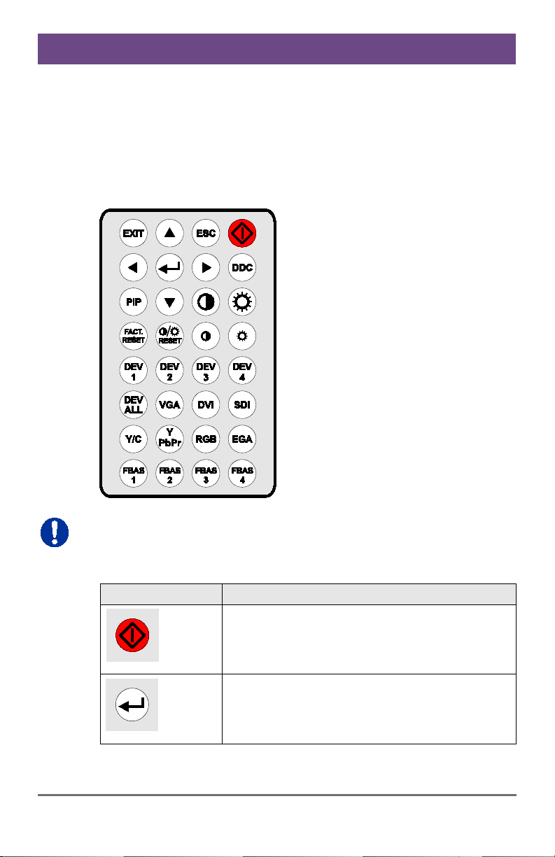
5.1 Infrared Remote Control
The Media / DVI Converter can be configured by means of an on-screen
display (OSD) in conjunction with infrared remote control to select and
configure menu items on the OSD.
In the OSD, only the navigation keys of the infrared remote control are
fun
ctional (red function key, <↵>, <EXIT>, <ESC> and cursor keys <◄>,
<►>, <▲>, <▼>
).
Button
Description
Open OSD or select menu.
Open OSD or select menu.

Media / DVI Converter
20 2021-10-14
Button
Description
Leave OSD.
Leave current menu and open upper menu level.
Navigate inside the OSD.
Select parameters with cursor keys <◄> and
<►>.
Read and use DDC from the connected monitor.
Execute Auto Configuration (VGA / RGB / EGA
input only)
Adjust picture contrast / brightness.
Reset the Media / DVI Converter to factory default.
Reset picture contrast / brightness to factory
default.
Other manuals for Draco 238 Series
1
Table of contents
Other Ihse Media Converter manuals


Popular Media Converter manuals by other brands

Snell Advanced Media
Snell Advanced Media MV-820 Quick setup guide

Linear Technology
Linear Technology LT1933 datasheet

DeLOCK
DeLOCK 86441 user manual

Rohde & Schwarz
Rohde & Schwarz TSME30DC instruction manual

Renishaw
Renishaw QUANTIC RESM40 installation guide

RSF Elektronik
RSF Elektronik MS 45 MO Mounting instructions


