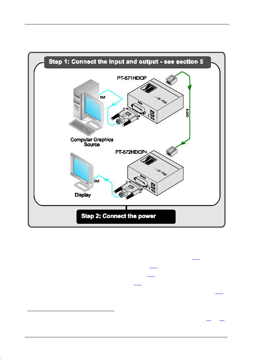
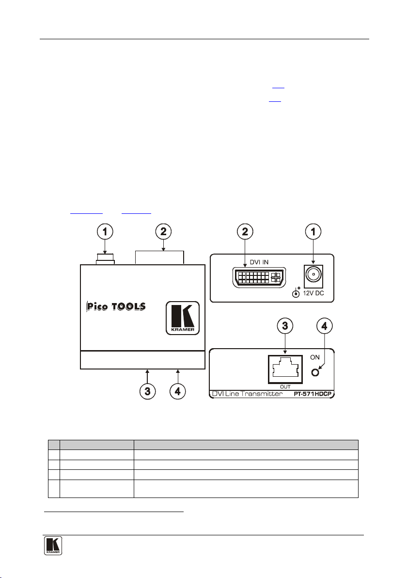
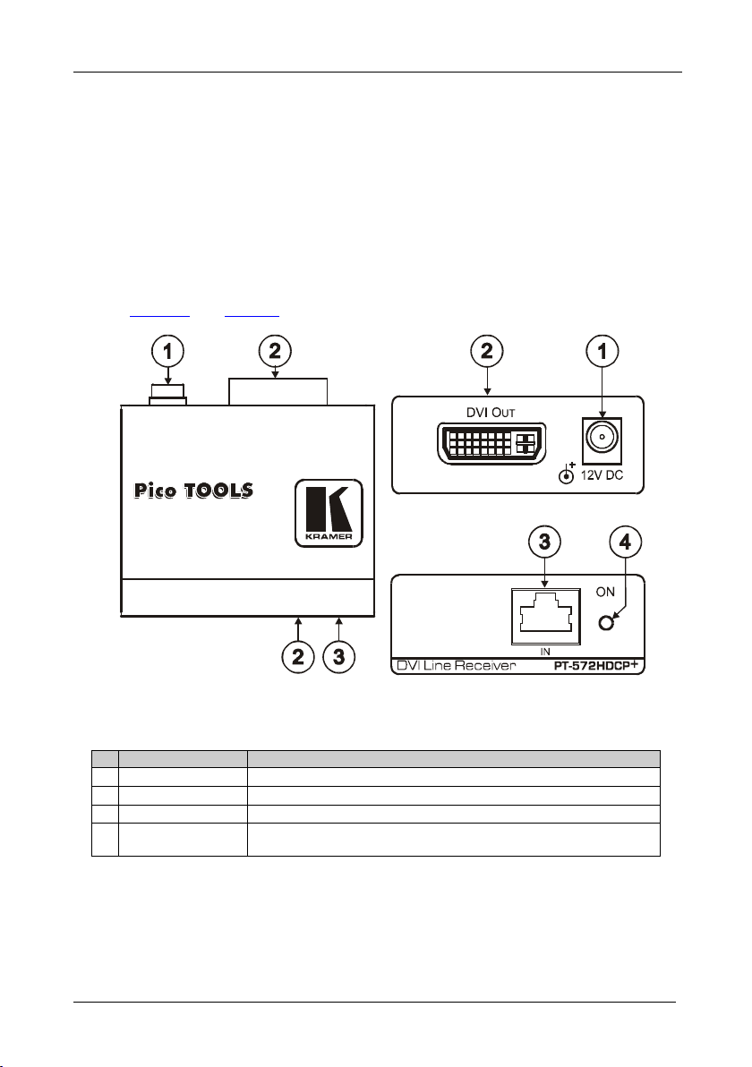
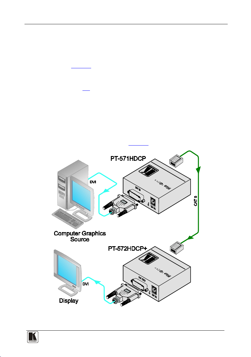
Kramer PT-572HDCP+ User manual

Kramer Electronics, Ltd.
Preliminary
USER MANUAL
Models:
PT-571HDCP DVI Line Transmitter
PT-572HDCP+ DVI Line Receiver

Contents
i
Contents
1Introduction 1
2Getting Started 1
2.1 Quick Start 2
3Overview 2
3.1 Summarizing the DVI Line Transmitter/Receiver System 3
3.2 About the Power Connect™ Feature 3
3.3 Using Twisted Pair Cable 4
3.4 About HDCP 4
3.5 Achieving the Best Performance 4
4Your PT-571HDCP/PT-572HDCP+ 5
4.1 Your PT-571HDCP DVI Line Transmitter 5
4.2 Your PT-572HDCP+ DVI Line Receiver 6
5Connecting the PT-571HDCP and PT-572HDCP+ 7
5.1 Wiring the CAT 5 LINE IN/LINE OUT RJ-45 Connectors 8
6Technical Specifications 8
Figures
Figure 1: PT-571HDCP DVI Line Transmitter 5
Figure 2: PT-572HDCP+ DVI Line Receiver 6
Figure 3: Connecting the PT-571HDCP/PT-572HDCP+ DVI Line Transmitter/Receiver 7
Figure 4: CAT 5 PINOUT 8
Tables
Table 1: PT-571HDCP DVI Line Transmitter Features 5
Table 2: PT-572HDCP+ DVI Line Receiver Features 6
Table 3: CAT 5 PINOUT 8
Table 4: Technical Specifications 8

Introduction
1
1
1 Introduction
Welcome to Kramer Electronics! Since 1981, Kramer Electronics has been
providing a world of unique, creative, and affordable solutions to the vast range
of problems that confront the video, audio, presentation, and broadcasting
professional on a daily basis. In recent years, we have redesigned and upgraded
most of our line, making the best even better! Our 1,000-plus different models
now appear in 11 groups1
Thank you for purchasing the Kramer PicoTOOLS™ PT-571HDCP DVI
Line Transmitter and the PT-572HDCP+DVI Line Receiver, which are
ideal for
that are clearly defined by function.
2
•Board, conference, and training rooms
:
•Presentation systems
•Signal distribution and home theater
Each package includes the following items:
•PT-571HDCP DVI Line Transmitter or PT-572HDCP+DVI Line Receiver
•Power adapter (12V DC Input) and this user manual3
2 Getting Started
We recommend that you:
•Unpack the equipment carefully and save the original box and
packaging materials for possible future shipment
•Review the contents of this user manual
•Use Kramer high-performance high-resolution cables4
1 GROUP 1: Distribution Amplifiers; GROUP 2: Switchers and Matrix Switchers; GROUP 3: Control Systems;
GROUP 4: Format/Standards Converters; GROUP 5: Range Extenders and Repeaters; GROUP 6: Specialty AV Products;
GROUP 7: Scan Converters and Scalers; GROUP 8: Cables and Connectors; GROUP 9: Room Connectivity;
GROUP 10: Accessories and Rack Adapters; GROUP 11: Sierra Products
2 Ultra-Compact PicoTOOLS™ - 4 units can be rack mounted side-by-side in a 1U rack space with the optional RK-4PT rack
adapter
3 Download up-to-date Kramer user manuals from our Web site at http://www.kramerelectronics.com
4 The complete list of Kramer cables is on our Web site at http://www.kramerelectronics.com

KRAMER: SIMPLE CREATIVE TECHNOLOGY
Overview
2
2.1 Quick Start
This quick start chart summarizes the basic setup and operation steps.
3 Overview
This section summarizes:
•The DVI Line Transmitter/Receiver System13.1,see section
•The power connect feature, see section 3.2
•Using Twisted Pair Cable, see section 3.3
•The HDCP standard, see section 3.4
•Recommendations for achieving the best performance, see section 3.5
1 For details of the PT-571HDCP DVI Line Transmitter and PT-572HDCP+ DVI Line Receiver, see sections 4.1 and 4.2,
respectively

Overview
3
3
3.1 Summarizing the DVI Line Transmitter/Receiver System
Using the PT-571HDCP DVI Line Transmitter with the PT-572HDCP+DVI
Line Receiver constitutes a DVI-to-twisted pair transmitter and receiver
system. The DVI Line Transmitter/Receiver system features:
•Maximum data rate/bandwidth up to 1.65Gbps
•HDTV compatibility and HDCP compliance
•EDID PassThru that passes EDID/HDCP signals from source to
display
•System Range1
•Power Connect™ that feeds 12V DC over the CAT 5 cable from
transmitter to receiver (see section
- Up to 90m (295ft) at 1080i, or up to 30m (98ft) at
1080p on shielded BC-DGKat524 cable; 90m (295ft) at 1080i, or up
to 70m (230ft) at 1080p on shielded BC-DGKat623 cable; 100m
(330ft) at 1080i or up to 90m (295ft) at 1080p on shielded
BC-DGKat7a23 cable
3.2)
•Two DVI-I connectors, that are compatible with all types of DVI
cables
Note that only the digital signal (DVI D) is available on the DVI connector.
3.2 About the Power Connect™ Feature
The Power Connect™ feature here means that only one unit in a system, the
transmitter or receiver, can be connected to a power source when the
devices are within 270 feet (90 meters) of each other. The Power Connect™
feature applies as long as the cable can carry power. The distance does not
exceed 90 meters on standard CAT 5 cable, for longer distances, heavy
gauge cable should be used2
.
1 Note that the transmission range depends on the signal resolution, graphics card and display used. The distance using non-
Kramer CAT 5, CAT 6 and CAT 7a cables may not reach these ranges
2 CAT 5 cable is still suitable for the video/audio transmission, but not for feeding the power at these distances

KRAMER: SIMPLE CREATIVE TECHNOLOGY
Overview
4
3.3 Using Twisted Pair Cable
Kramer engineers have developed special twisted pair cables to best match
our digital twisted pair products; the Kramer: BC-DGKat524 (CAT 5 24
AWG), the Kramer: BC-DGKat623 (CAT 6 23 AWG cable), and the
Kramer: BC-DGKat7a23 (CAT 7a 23 AWG cable). These specially built
cables significantly outperform regular CAT 5/CAT 6/CAT 7a cables.
3.4 About HDCP
The High-Bandwidth Digital Content Protection (HDCP) standard1
3.5 Achieving the Best Performance
, protects
digital video and audio signals transmitted over DVI or HDMI connections
between two HDCP-enabled devices to eliminate the reproduction of
copyrighted material. To protect copyright holders (such as movie studios)
from having their programs copied and shared, the HDCP standard provides
for the secure and encrypted transmission of digital signals.
To achieve the best performance:
•Use only good quality connection cables2
•Avoid interference from neighboring electrical appliances that may
adversely influence signal quality and position your Kramer devices
away from moisture, excessive sunlight and dust
to avoid interference,
deterioration in signal quality due to poor matching, and elevated
noise levels (often associated with low quality cables).
1 Developed by Intel
2 Available from Kramer Electronics on our Web site at http://www.kramerelectronics.com

Your PT-571HDCP/PT-572HDCP+
5
5
4 Your PT-571HDCP/PT-572HDCP+
This section describes the:
•PT-571HDCP DVI Line Transmitter, see section 4.1
•PT-572HDCP+DVI Line Receiver, see section 4.2
4.1 Your PT-571HDCP DVI Line Transmitter
The PT-571HDCP DVI Line Transmitter receives a DVI signal, encodes it, and
transmits it over a CAT 5 cable to the PT-572HDCP+.The PT-571HDCP has:
•A DVI input connector
•An RJ-45 CAT 5 output connector
•One power status LED
Figure 1and Table 1define the PT-571HDCP:
Figure 1: PT-571HDCP DVI Line Transmitter
Table 1: PT-571HDCP DVI Line Transmitter Features
#
Feature
Function
1 12V DC +12V DC connector for powering the unit
2 DVI IN Connector Connect to the DVI source
3 OUT RJ-45 Connector Connect to the IN RJ-45 connector on the PT-572HDCP+
4 ON LED Lights only when the machine is powered (whether directly from the
power adapter or via the PT-572HDCP+) and an input1
1 Note, if no input is connected the unit invokes the power save mode automatically turning off the power
is connected

KRAMER: SIMPLE CREATIVE TECHNOLOGY
Your PT-571HDCP/PT-572HDCP+
6
4.2 Your PT-572HDCP+ DVI Line Receiver
The PT-572HDCP+DVI Line Receiver receives an encoded signal over a
CAT 5 cable transmitted from the PT-571HDCP, decodes it, and converts
it to a DVI output.
The PT-572HDCP+has:
•A DVI output connector
•An RJ-45 CAT 5 input connector
•One power status LED
Figure 2and Table 2define the PT-572HDCP+:
Figure 2: PT-572HDCP+ DVI Line Receiver
Table 2: PT-572HDCP+ DVI Line Receiver Features
#
Feature
Function
1 12V DC +12V DC connector for powering the unit
2 DVI OUT Connector Connect to the DVI acceptor
3 IN RJ-45 Connector Connect to the OUT RJ-45 connector on the PT-571HDCP
4 ON LED Lights red when receiving power only, orange when output and power are
attached, and yellow when both an active input and output are attached

Connecting the PT-571HDCP and PT-572HDCP+
7
7
5 Connecting the PT-571HDCP and PT-572HDCP+
You can use the PT-571HDCP DVI Line Transmitter with the PT-572HDCP+
DVI Line Receiver to configure a DVI transmitter/receiver system.
To connect the PT-571HDCP to the PT-572HDCP+, as illustrated in the
example in Figure 3, do the following:
1. Connect the CAT 5 OUT RJ-45 connector on the PT-571HDCP to the
CAT 5 IN RJ-45 connector on the PT-572HDCP+via a CAT 5 cable
(see section 5.1).
2. On the PT-571HDCP, connect a DVI source (for example, a computer
graphics source) to the DVI IN connector.
3. On the PT-572HDCP+, connect the DVI OUT connector to a DVI
acceptor (for example, a display).
4. Connect the 12V DC power adapter to the power socket on the
PT-571HDCP or the PT-572 HDCP + and connect the adapter to the
mains electricity (not shown in Figure 3).
Figure 3: Connecting the PT-571HDCP/PT-572HDCP+ DVI Line Transmitter/Receiver

KRAMER: SIMPLE CREATIVE TECHNOLOGY
Technical Specifications
8
5.1 Wiring the CAT 5 LINE IN/LINE OUT RJ-45 Connectors
Table 3and Figure 4define the CAT 5 pinout, using a straight pin-to-pin
cable with RJ-45 connectors (note, that the cable Ground shielding must
be connected/soldered to the connector shield):
Table 3: CAT 5 PINOUT Figure 4: CAT 5 PINOUT
36
781 2 5
4
145 78632
EIA /TIA 568A EIA /TIA 568B
PIN
Wire Color
PIN
Wire Color
1 Green/White 1 Orange/White
2 Green 2 Orange
3 Orange/White 3 Green/White
4 Blue 4 Blue
5 Blue/White 5 Blue/White
6 Orange 6 Green
7 Brown/White 7 Brown/White
8 Brown 8 Brown
Pair 1 4 and 5 Pair 1 4 and 5
Pair 2 3 and 6 Pair 2 1 and 2
Pair 3 1 and 2 Pair 3 3 and 6
Pair 4 7 and 8 Pair 4 7 and 8
6 Technical Specifications
ThePT-571HDCP/PT-572HDCP+ technical specifications are shown in
Table 4.
Table 4: Technical Specifications1
PT-571HDCP PT-572HDCP+
INPUTS: 1 DVI, 1.2Vpp on a DVI Molex
24pin female connector; DDC
signal 5Vpp (TTL)
1 RJ-45 connector
OUTPUTS: 1 RJ-45 connector 1 DVI, 1.2Vpp on a DVI Molex 24-pin
female connector; DDC signal 5Vpp (TTL)
BANDWIDTH: Supports up to 1.65Gbps
POWER SOURCE: 12V DC, 250mA 12V DC, 250mA
DIMENSIONS: 6.2cm x 5.2cm x 2.4cm (2.4" x 2.1" x 1") W, D, H.
WEIGHT: 0.14kg (0.3lbs)
ACCESSORIES: Power supply, mounting bracket
OPTIONS: 19” RK-4PT rack adapter, Kramer DVI cables
2
1 Specifications are subject to change without notice
and BC-DGKat524 (CAT 5 24
AWG), BC-DGKat623 (CAT 6 23 AWG) and BC-DGKat7a23 (CAT 7a 23 AWG)
cables
2 The complete list of Kramer cables is on our Web site at http://www.kramerelectronics.com

9
9
LIMITED WARRANTY
WHOIS PROTECTED?
WHAT IS COVEREDAND WHAT IS NOTCOVERED
WH AT WE WI LLPAY FOR AN D WHAT WE WILL NOT PAY FOR
HOW YOU CAN GET WARRANTY SERVICE
LIMITATION OFIMPLIEDWARRANTIES
EXCLUSIONOFDAMAGES
CAUTION!
Kramer Electronics (hereafter ) warrants this product free from defects in material and workmanship under the
following terms.
Kramer
HOW LONGIS THE WARRANTY
Labor and parts are warranted for three years from the date of the first customer purchase.
Only the first purchase customer may enforce this warranty.
We will pay labor and material expenses for covered items.We will not pay for the following:
The liability of Kramer for any effective products is limited to the repair or replacement of the product at our option. Kramer shall
not be liable for:
Thiswarranty gives you specific legal rights, andyou may also have other rights, which varyfrom place to place.
All products returned to Kramer for service must have prior approval. This may be obtained from your dealer.
Thisequipment has been tested todetermine compliance with the requirements of:
EN-50081: "Electromagnetic compatibility(EMC);
generic emission standard.
Residential, commercial and light industry"
EN-50082: "Electromagnetic compatibility(EMC) generic immunity standard.
Part 1: Residential, commercialand lightindustry environment".
CFR-47: FCC* Rules and Regulations:
Part 15: “Radio frequency devices
Subpart B Unintentional radiators”
Except as below, this warranty covers all defects in material or workmanship in this product. The following are not covered
by the warranty:
1. Any product which is not distributed by Kramer, or which is not purchased from an authorized Kramer dealer. If you are
uncertain as to whether a dealer is authorized, please contact Kramer at one of the agents listed in the Web site
www.kramerelectronics.com.
2. Any product, on which the serial number has been defaced, modified or removed, or on which the WARRANTY VOID
TAMPERED sticker has been torn,
3. Damage, deterioration or malfunctionresulting from:
i) Accident, misuse, abuse, neglect, fire, water, lightning or other acts of nature
ii) Product modification, or failureto followinstructions supplied with the product
iii) Repair or attempted repair by anyone not authorized by Kramer
iv) Any shipment of the product (claims must be presented to the carrier)
v) Removal or installationof the product
vi) Any other cause, which does not relate to a product defect
vii) Cartons, equipment enclosures, cables or accessoriesused in conjunctionwith the product
1. Removal or installationscharges.
2. Costs of initial technical adjustments (set-up), including adjustment of user controls or programming. These costs are the
responsibility of the Kramer dealer from whom the product was purchased.
3. Shipping charges.
1. To obtain service on you product, you must take or ship it prepaid to any authorized Kramer service center.
2. Whenever warranty service is required, the original dated invoice (or a copy) must be presented as proof of warranty
coverage, and should be included in any shipment of the product. Please also include in any mailing a contact name,
company, address, and a description of the problem(s).
3. For the name of the nearest Kramer authorized service center, consult your authorized dealer.
All implied warranties, including warranties of merchantability and fitness for a particular purpose, are limited in duration to
the length of this warranty.
1. Damage to other property caused by defects in this product, damages basedupon inconvenience, loss of use of the product, loss
of time, commercialloss; or:
2. Any other damages, whether incidental, consequential or otherwise. Some countries may not allow limitations on how long an
implied warranty lasts and/or do not allow the exclusion or limitation of incidental or consequential damages, so the above
limitations and exclusions may not apply toyou.
Servicing the machines can only be done by an authorized Kramer technician. Any user who makes changes or
modifications to the unit without the expressed approval of the manufacturer will void user authority to operate the
equipment.
Use the supplied DC power supply to feed power to the machine.
Please use recommended interconnection cables to connect the machine to other components.
IF reattached, removed or otherwise interfered with.
* FCC and CE approvedusing STP cable (for twistedpair products)
NOTE:
Part 1:

Kramer Electronics, Ltd.
Web site: www.kramerelectronics.com
E-mail: info@kramerel.com
P/N: 2900-000689 REV 3
For the latest information on our products and a list of Kramer
distributors, visit our Web site: www.kramerelectronics.com
where updates to this user manual may be found.
We welcome your questions, comments and feedback.
Caution
Safety Warning:
Disconnect the unit from the power supply before
opening/servicing.
This manual suits for next models
1
Table of contents
Other Kramer Transmitter manuals

Kramer
Kramer F-121 User manual

Kramer
Kramer SID-VGA User manual

Kramer
Kramer 611T User manual

Kramer
Kramer WP-110xl User manual

Kramer
Kramer TP-210 User manual

Kramer
Kramer TP-102HD User manual

Kramer
Kramer TP-185 User manual

Kramer
Kramer SID-X1 User manual

Kramer
Kramer VP-428H2 User manual

Kramer
Kramer VP-200XLT User manual

Kramer
Kramer Cobra TS2 User manual

Kramer
Kramer 610T User manual

Kramer
Kramer 691 User manual

Kramer
Kramer WP-110xl User manual

Kramer
Kramer WP-110 User manual

Kramer
Kramer TP-410 User manual

Kramer
Kramer SID-X3N User manual

Kramer
Kramer TP-202 User manual

Kramer
Kramer WP-789T User manual

Kramer
Kramer SID-X1N User manual