USER'S GUIDE____________________________________________________________________
4 ___________________________________________________________________ M010022EN-F
CHAPTER 5
MAINTENANCE............................................................................................27
Replacing the Probe...............................................................27
Transmitter with Integrated Probe (Wall Model)..................27
Transmitter with Remote Probe...........................................27
Check and Calibration............................................................28
Comparison with Calibrated Probe......................................28
Calibrator GMK220..............................................................28
On-site Checking and Adjusting with Reference Gas and
GM70 Hand-Held Meter......................................................29
Two-Point Adjustment Procedure........................................30
One-Point Adjustment Procedure........................................32
Technical Support ..................................................................33
Product Returns......................................................................33
CHAPTER 6
TECHNICAL DATA ......................................................................................35
Technical specifications........................................................35
Inputs and outputs...............................................................36
Operating conditions............................................................36
Mechanics ...........................................................................36
Electromagnetic compatibility..............................................37
Accessories.........................................................................37
Dimensions in mm (inches)...................................................38
List of Figures
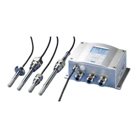
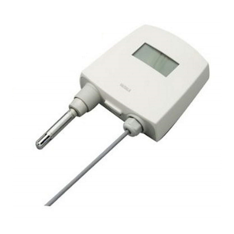
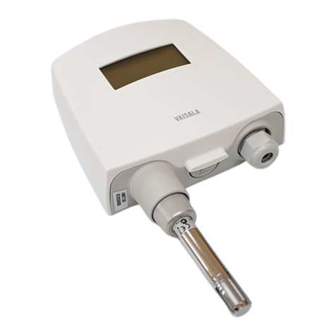
Figure 1 GMT220 with Integrated Probe ..................................................9
Figure 2 GMT220 with Probe Installed Remotely...................................10
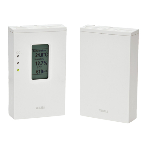
Figure 3 LED Indicators and Optional Display........................................11
Figure 4 Mounting the Transmitter..........................................................13
Figure 5 Gasket Ring..............................................................................14
Figure 6 Electrical Connections and Jumpers........................................15
Figure 7 AC Connections........................................................................17
Figure 8 19040GM Serial COM Adapter.................................................17
Figure 9 Serial Port and Cable Direction................................................19
Figure 10 Field Check Adapter.................................................................30
Figure 11 Location of the GM70 Adjustment Button.................................31
Figure 12 Transmitter................................................................................38
Figure 13 Mounting Plate..........................................................................39
Figure 14 Probe GMP221.........................................................................39
Figure 15 Probe GMP222.........................................................................40
Figure 16 Mounting Flange GM45156SP.................................................40
List of Tables
Table 1 Manual Revisions.......................................................................5
Table 2 Related Manuals.........................................................................6
Table 3 Serial Settings...........................................................................20
Table 4 Serial Commands.....................................................................20
Table 5 Altitude and Atmospheric Pressure..........................................22
Table 6 Error Messages ........................................................................25
