IKAR DB-AR Product guide

1
Prüfbuch und Gebrauchsanleitung
Log book and instructions for use
Dreibaum DB-AR
Anschlageinrichtung
nach EN 795:2012-10 Typ B und CEN/TS 16415:2013-04
Tripod DB-AR
Load fastening device
according to EN 795:2012-10 Type B and CEN/TS
16415:2013-04
PRÜFBUCH IMMER BEIM GERÄT AUFBEWAHREN !
VOR GEBRAUCH ANLEITUNG SORGFÄLTIG LESEN !
ALWAYS KEEP THIS BOOKLET WITH THE DEVICE!
CAREFULLY READ THESE INSTRUCTIONS BEFORE USING THIS PRODUCT!
GR
SK
GB ES FR IT PT
D NL PL RO DK SE FI NO HU

2 3
Dreibaum DB-AR / Tripod DB-AR
nach EN 795 Typ B:2012-10, CEN/TS 16415:2013-04
according to EN 795 Type B:2012-10, CEN/TS 16415:2013-04
Eingeschaltete Stelle: Prüf- und Zertizierungsstelle des
FA PSA, 42781 Haan, CE0299 - Engaged body: Testing
and certifying body of the FA PSA, 42781 Haan, CE0299
Kaufdatum/
date of purchase: ___________________
Datum der Erstbenutzung/
date of rst use: ___________________
Position/Item
Nächste Revision
next revision
Verriegelungsstifte auf Funktion prüfen
Functional test of the locking
pins
Lesbarkeit des Typenschildes prüfen
check type plate legibility
Befestigungshalterung HRA prüfen
(optional) Inspect the attachment
rack of the fall protection system
(optional)
Funktion und Zustand der Rollen
prüfen/ Inspect the function and
condition of the wheels
Sichtprüfung auf Risse /
Korrosion visual check for cracks
/ corrosion
Steckbolzen auf Funktion prüfen
Functional test of the locking
pins
Funktion der Seilrolle und Karabiners
prüfen/ Functional test of rope
pulley and snap-hook
Anschlagpunkte Ringösen prüfen
Inspect grommets at attachment
points
Dreibaum auf Verformung prüfen
Tripod deformation inspection
Verschraubungen auf Festsitz prüfen
Inspection of screw connections
for tight t
Grund der Bearbeitung / Purposes:
Festgestellte Mängel / observed
defects:
Datum der Abnahme/Date of certi-
cation: Unterschrift des Prüfers /
signature of the inspector:
Bemerkungen/Comments:
Prüfbuch / Log book
Konformitätserklärung/Conformity http://ikar-gmbh.de/index.php/de/service/download

3
Position/Item
Das IKAR Höhensicherungsgerät HRA mit Rettungshubeinrichtung ist nach der Prüf-/ Wartungsanweisung für IKAR-
Höhensicherungsgeräte zu prüfen!
Dieses Prüfbuch mit Gebrauchsanleitung gehört zur Anschlageinrichtung Dreibaum DB-AR nach EN 795 Typ
B:2012-10, CEN/TS 16415:2013-04 und muss am Einsatzort verfügbar sein. Wird das Gerät wiederverkauft, muss
dieses Prüfbuch mit Gebrauchsanleitung in Landessprache beigefügt sein.
The IKAR fall protection device HRA with rescue lifting gear must be inspected according to the inspection and
maintenance instructions for IKAR fall protection systems!
This log book with instructions for use belong to the Tripod DB-AR according to EN 795 Type B:2012-10, CEN/TS
16415:2013-04 and must be available at the location of use. If the device is resold, these instructions for installation
and use must be enclosed in the national language.

4 5

5
Inhaltsverzeichnis
Directory
Prüfbuch / Log book...................................................................................2
DEUTSCH ....................................................................................................6
ENGLISH.................................................................................................... 11
FRANÇAIS.................................................................................................16
ESPAÑOL ..................................................................................................21
ITALIANO...................................................................................................26
PORTUGUÊS.............................................................................................31
POLSKI ......................................................................................................36
ROMÂNĂ ...................................................................................................41
MAGYAR....................................................................................................46
NEDERLANDS...........................................................................................51
DANSK.......................................................................................................56
SVENSKA ..................................................................................................61
SUOMEKSI ................................................................................................66
NORSK.......................................................................................................71
SLOVENSKY .............................................................................................76
ΕΛΛΗΝΙΚΑ.................................................................................................81

6 7
1. Diese Anschlageinrichtung ist für die Sicherung von 1 Person nach EN 795:2012-10 Typ B und für die
Sicherung von 3 Person nach CEN/TS 16415:2013-04 gegen Absturz und zur Rettung geprüft und zugelassen.
In Verbindung mit zusätzlich notwendigen Auffanggurten nach EN 361, IKAR Höhensicherungsgeräten EN
360, IKAR Höhensicherungsgeräten vom Typ HRA mit Rettungshubeinrichtung gemäß EN 360 / EN 1496
muss sichergestellt sein, dass die Kraft, die während des Auffangvorganges auf den Benutzer wirkt auf max.
6kN begrenzt wird. Die Anschlageinrichtung und die Höhensicherungsgeräte sind nur bestimmungsgemäß zu
verwenden.
Hinweis: Das IKAR Höhensicherungsgerät HRA mit Rettungshubeinrichtung ist nicht im Lieferumfang
enthalten!
2. Bei Nichtbeachtung der Gebrauchsanleitung besteht Lebensgefahr. Im Falle eines Sturzes ist ein längeres
Hängen der Person als 15 Minuten unbedingt auszuschließen (Schockgefahr).
3. Es muss ein Plan der Rettungsmaßnahmen vorhanden sein, in dem alle bei der Arbeit möglichen Notfälle
berücksichtigt sind.
4. Die Anschlageinrichtung darf nur von Personen benutzt werden, die entsprechend ausgebildet und fachkundig
sind. Gesundheitliche Beeinträchtigungen dürfen nicht vorliegen! (z.B. Alkohol-, Drogen-, Medikamenten- oder
Kreislaufprobleme)
5. Ein IKAR Höhensicherungsgerät HRA mit Rettungshubeinrichtung kann im Einsatz nur eine Person schützen,
kann jedoch nacheinander von mehreren Personen genutzt werden.
6. Es ist wesentlich für die Sicherheit, dass die Aufstellung des IKAR Dreibaumes DB-AR senkrecht und standsi-
cher erfolgt. Achtung: Der Dreibaum darf keinesfalls auf öligen oder anderweitig rutschigen Böden eingesetzt
werden !
7. Die Einrichtung sollte möglichst lotrecht über den Kopf der zu sichernden Person angeordnet werden, um beim
Fallen ein Pendeln auszuschließen. Die Art der Anwendung ist so zu wählen, dass der freie Fall und die Ab-
sturzhöhe auf ein Mindestmaß beschränkt wird. Nach der Befestigung des IKAR Höhensicherungsgerätes HRA
in der Halterung am IKAR Dreibaum und einlegen des ausziehbaren Verbindungsmittels in die Umlenkrolle, ist
das Ende (Karabinerhaken) an der Auffangöse des Auffanggurtes zu befestigen. Die einwandfreie Funktion des
Karabinerhakens ist zu prüfen. Der Sicherheitsschutz für die Arbeitsperson ist hergestellt.
8. Vor jeder Benutzung ist die Lesbarkeit der Produktkennzeichnung zu kontrollieren und eine Sichtprüfung der
Anschlageinrichtung und ihrer Anbauteile auf augenscheinliche Mängel durch zu führen (Gemäß Liste Seite 2).
9. Eine beschädigte oder durch Sturz beanspruchte Ausrüstung - oder wenn Zweifel über den sicheren Zustand
der Ausrüstung bestehen - ist sofort dem Gebrauch zu entziehen! Sie darf erst nach Überprüfung und schriftli-
cher Freigabe durch eine sachkundige Person weiter verwendet werden.
10. Je nach Beanspruchung, mindestens jedoch alle zwölf Monate muss die Anschlageinrichtung, also der IKAR
Dreibaum und das optionale Höhensicherungsgerät vom Hersteller oder vom Hersteller geschulten und
autorisierten Personen überprüft werden. Dies muss in den mitgelieferten Prüfbüchern dokumentiert werden.
Die Wirksamkeit und Haltbarkeit des IKAR Dreibaumes und des optionalen IKAR Höhensicherungsgerätes
hängen von der regelmäßigen Prüfung ab.
11. Reparaturen dürfen nur vom Hersteller ausgeführt werden.
12. Die DGUV Regeln 112-198 und 112-199 sind zu beachten.
13. Die zulässige Belastung der Anschlageinrichtung entspricht der EN 795:2012 Typ B für die Sicherung und
Rettung von 1 Person und CEN/TS 16415:2013-04 von maximal 3 Personen.
14. Der IKAR Dreibaum DB-AR, auch das optionale IKAR Höhensicherungsgerät, sind vor den Einwirkungen von
Schweißammen und -funken, Feuer, Säuren, Laugen sowie extreme Temperaturen und korrosiven Umwelt-
einüssen zu schützen. Während des Transportes darf der Dreibaum nicht durch Stoßeinwirkung beschädigt
werden können.
15. Für den Transport des IKAR Dreibaumes DB-AR werden min. 2 Personen benötigt.
16. Es dürfen keine Veränderungen und Ergänzungen an der Einrichtung vorgenommen werden - sonst besteht
Lebensgefahr.
Vor Inbetriebnahme ist die Gebrauchsanleitung unbedingt ganz durchzulesen und inhaltlich zu verstehen.
Die technischen Daten und die entsprechend beigefügte Gebrauchsanleitung für das IKAR-Höhensicherungs-
gerät HRA mit Rettungshubeinrichtung ist unbedingt zu beachten !
2. Gebrauchanleitung Sicherheitsbereich
3. Technische Daten Dreibaum Typ DB-AR
Max. Belastung: 3 Personen
Höhenverstellbereich: 1,13 m - 1,78 m Aufstell-
durchmesser: 0,99 - 1,55 m
Gerätegewicht: 28 kg ohne IKAR HRA-
max. Tragkraft 300 kg
DEUTSCH

7
0299
Richtlinie/Directive 2006/42/EG
46000005054
IKAR GmbH
36041 Fulda/GERMANY
www.ikar-gmbh.de
Dreibaum DB-AR
EN 795 Typ B:2012-10,
CEN/TS 16415:2013-04
Serien Nr.: 38/09-2016
Herstelldatum: 09-2016
Max. Belastung: 3 Personen
Max. Tragkraft: 300 kg
0299
Abb. 1
IKAR GmbH
D 36041 Fulda
Abb. 2
Halterung HRA 9,5-33/42
Bestandteil
Dreibaum Typ DB - A1/ A2/ AR
Baujahr : 03/2015
Fabrik-Nr.: 123457
1
2
3
4
5
6
7
8
9
10
21
11
1
2
3
4
5
6
7
8
9
10
11
12
2017
2016
1
2
3
4
5
6
7
8
9
10
11
21
1
2
3
4
5
6
7
8
9
10
11
12
2017
2016
Typenschild
Hersteller Gebrauchs-
anleitung
beachten
Herstelldatum
Seriennummer
Prüfplakette
Typenbezeichnung
Überwachende
Stelle
zulässige
Belastung
Bestandteil
Dreibaum DB - A1/A2/AR
Baujahr : 03/2015
Fabrik-Nr.: 123458
0299
Umlenkrolle / Deflection roller
max. Belastung: / max. load:
1 Person
IKAR GmbH
D 36041 Fulda
1
2
3
4
5
6
7
8
9
10
11
12
1
2
3
4
5
6
7
8
9
10
11
12
2017
2016
Abb. 3
Darstellung (Abb. 4) zeigt die
Einrichtung mit Bestandteil:
Halterung für IKAR-HRA Geräte
Rollen
Abspannband
Verriegelungs-
bolzen
* Halterung HRA
schwenk- undverrie-
gelbare Querstreben
* = Bestandteil Zubehör
lenk- und bremsbare
Rolle
klappbare
Handdeichsel
Arretierungsstift
pro Bein
Typenschild
Anschlagpunkt
Ringösen
Konusscheibe
Sterngriffmutter
Ringöse
4. Übersicht Abb. 4
Pos. 13
Pos. 2
Pos. 1
Pos. 7
Pos. 6
Pos. 14
Pos. 8
Pos. 5
Pos. 4
Pos. 3
Pos. 9
Pos. 11
Pos. 10
Steckbolzen
Pos. 12
DEUTSCH
8 9
Abb. 5
Abb. 6
1
Abb. 6
Abb. 9
Abb. 10
Abb. 8
Abb. 7
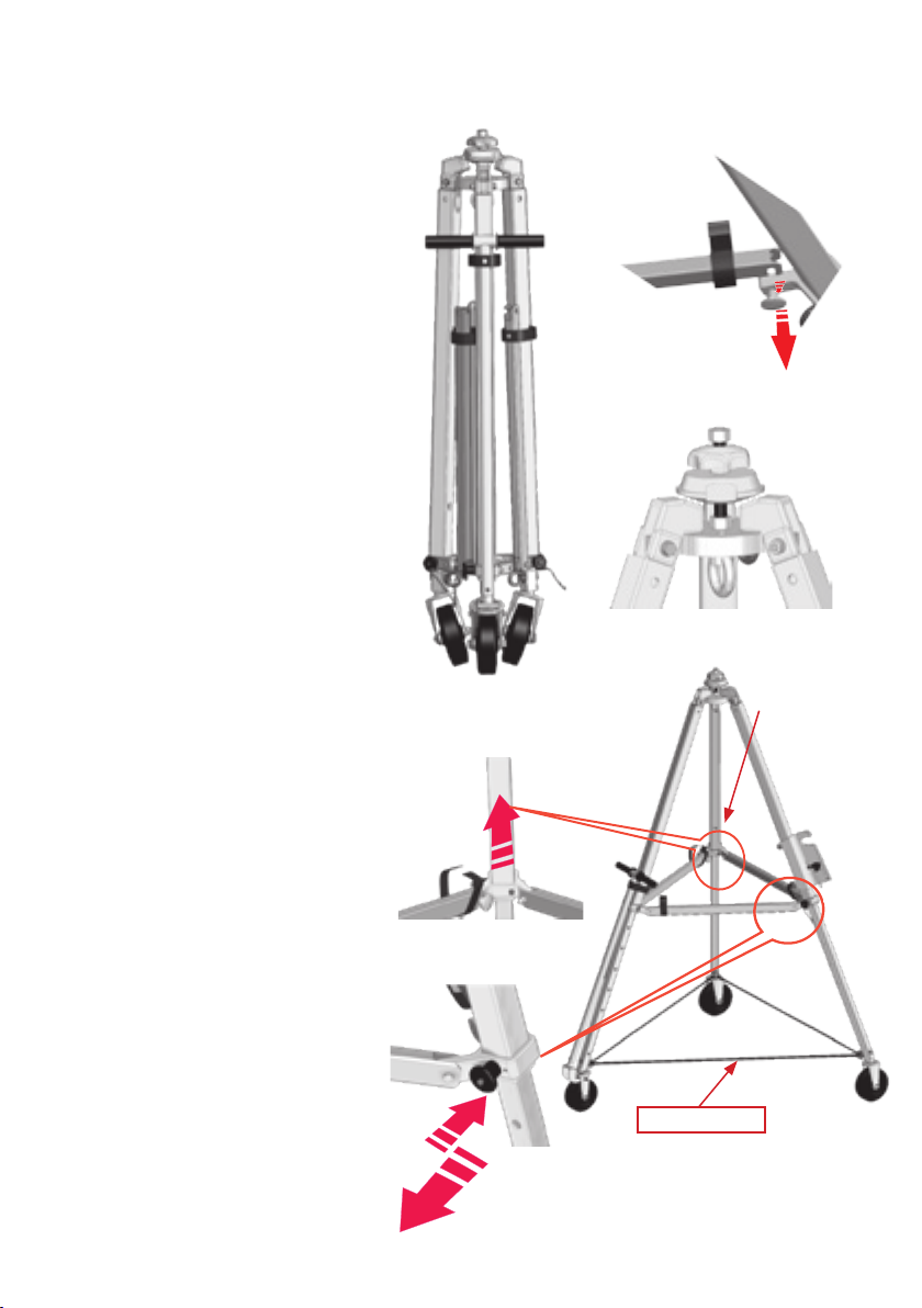
5. Herstellen der Einsatzbereitschaft:
Dreibaum senkrecht aufstellen und Sterngriff-
mutter Pos. 1 durch drehen
gegen den Uhrzeigerdrehsinn lösen. Konus-
scheibe Pos. 2 muß frei nach
oben beweglich sein. (Abb. 5)
Hinweis: Dreibaum (Abb. 5) steht auf
den Rollen nicht eigenstabil.
Die Beine, beginnend mit dem Bein, an dem
die Handdeichsel befestigt ist, seitlich nach
aussen klappen. Klettbänder öffnen und
Querstreben Pos.7 waagerecht klappen, den
Verriegelungsbolzen Pos.14 (Abb.6) am Pilz-
griff herausziehen und Querstrebe einlegen.
Pilzgriff loslassen. Verriegelungsbolzen rastet
ein. Querstrebe auf richtiger Verriegelung
prüfen. So sinn-gemäß mit den 2 weiteren
Querstreben verfahren. Sterngriffmutter am
Kopf durch drehen im Uhrzeigerdrehsinn
gegen die Konusscheibe (Abb.7) festdrehen.
Somit sind die Beine fest gesichert.
Um die einzeln ausschiebaren Teleskopbeine
auf die entsprechende Höhe zu bringen, ist
zuerst der Steckbolzen Pos.12 (Abb.10) durch
Daumendruck zu entriegeln und heraus zu
ziehen.
Die Teleskopbeine auf die gewünschte Länge
ausziehen und danach mit Steckbolzen
Pos.12 wieder sichern. Um Unebenheiten
des Bodens auszugleichen können die Beine
unterschiedlich ausgeschoben werden. Mit
den zwei anderen Teleskopbeinen ist genau
so zu verfahren. Bei voller Auszugslänge
rasten die Teleskop-beine am Endanschlag
automatisch durch einen Arretierungsstift ein.
Zum Einschieben den Arretierungsstift einfach
wieder eindrücken.
Danach den Dreibaum ausrichten und
aufstellen. Zur weiteren Sicherung ist das
mitgelieferte Spannband Pos.13 (Abb.9)
immer durch die unteren Ringösen Pos.10 zu
ziehen und zu straffen.
Hinweis: Wenn die klappbare Handdeichsel
Pos.8 (Abb.9) aus-geklappt ist, wird automa-
tisch die Rolle gebremst. Dies gilt ebenso
auch in der angeklappten Stellung.Der Abbau
des Rollendreibaumes DB-AR ist sinngemäß
in umgekehrter Reihenfolge vorzunehmen.
mögliche Position
2. Halterung für
IKAR-HRA Geräte
Spannband
2
1
DEUTSCH

9
M 10 x 75
M 8 x 40
Abb. 13
Abb. 12
Abb. 11
Abb. 15
Abb. 14
Abb. 16
Oben
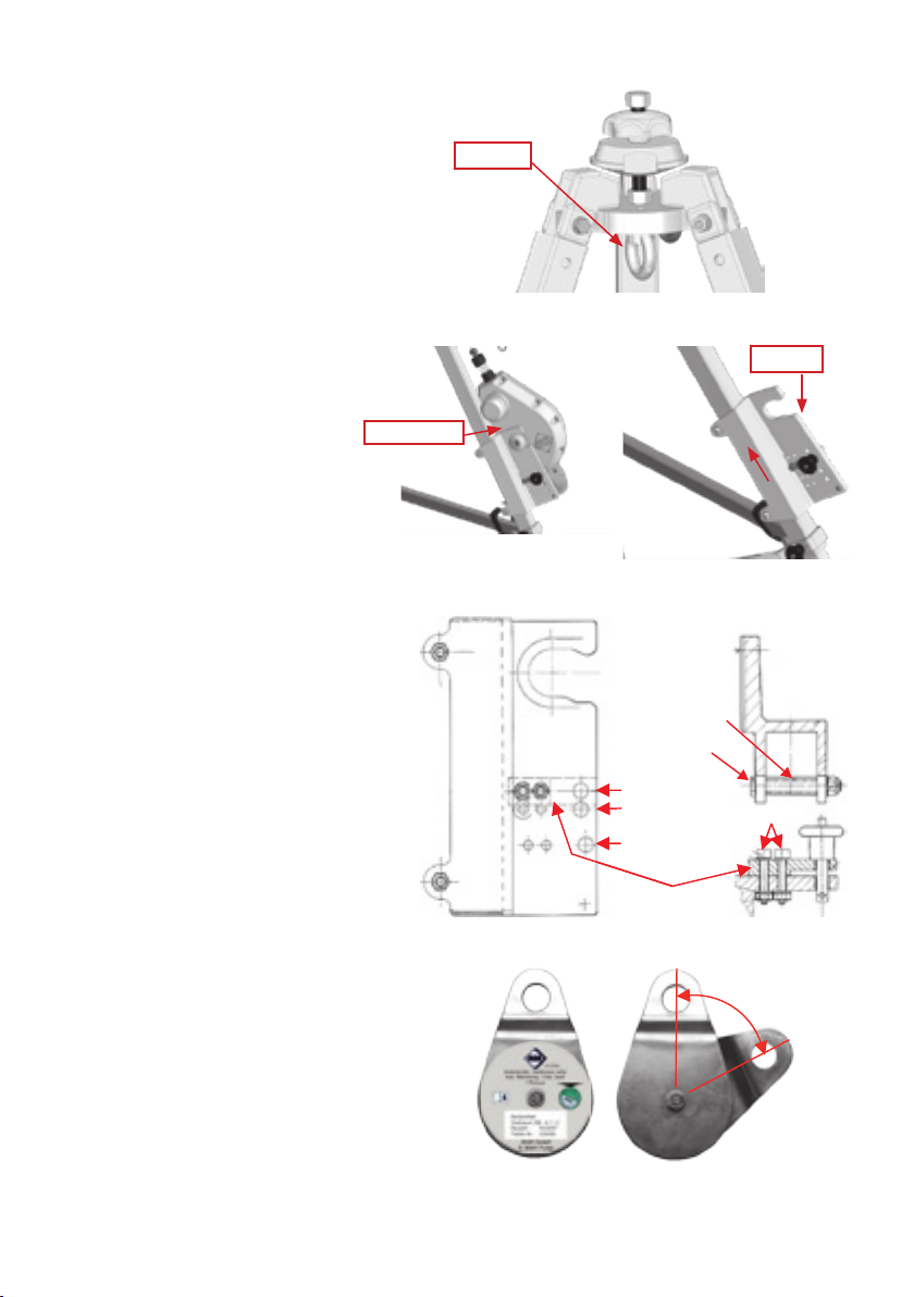
7. Optionale Bestandteile:
IKAR Höhensicherungsgerät HRA mit
Rettungshubeinrichtung
Das IKAR Höhensicherungsgerät HRA mit
Rettungshubeinrichtung wird mittels der
Halterung an dem Bein befestigt, auf dem das
Typenschild befestigt ist.
Hierzu erst die Halterung Pos. 6 (Abb.
12,13 u. 14) am Bein so montieren, das der
Sicherungsposten im Falle einer Rettung die
Rettungshubkurbel des IKAR HRA-Gerätes
einwandfrei bedienen kann. Die richtige
Klemmspannung der Halterung wird durch
die Länge (45,8 mm) der mitgelieferten
Distanzhülsen erreicht. Das Anzugsmoment
der Sechskantschrauben, Güteklasse 8.8 M
10x75 beträgt 49 Nm. Die Sicherungsleiste
ist entsprechend der Gerätegröße zu
positionieren. Das Anzugsmoment der Zylin-
derkopfschrauben der Güteklasse 8.8 M 8 x
40 beträgt 20 Nm. Das IKAR HRA Gerät in die
Halterung einsetzen. Die Sicherung des IKAR
HRA-Gerätes erfolgt mittels des Steckbolzens
an der Halterung
Achtung: Es dürfen nur IKAR Halterungen
montiert werden. In IKAR Halterungen
dürfen nur IKAR Geräte montiert werden.
Umlenkrolle mit Karabinerhaken:
Die Umlenkrolle (Abb. 15+16) dient zur
Führung und Umlenkung des Stahlseiles vom
IKAR Höhensicherungsgerät Typ HRA.
Dazu die geschlossene Umlenkrolle (Abb. 15)
durch gegenseitiges Verdrehen der beiden
Bleche öffnen (Abb. 16) und Stahlseil in die
Führungsrille einlegen. Danach die beiden
Bleche zurückdrehen.
Karabinerhaken in die Umlenkrolle einhängen
und am Anschlagpunkt Pos. 3 des Dreibau-
mes einklinken.
Achtung: Nur Karabinerhaken aus Stahl
nach EN 362 Kl.B einsetzen.
Die Schraubsicherung am Karabinerhaken
fest anziehen. Seilrolle auf Leichtgängigkeit
prüfen
Hinweis: Das IKAR HRA-Gerät zieht das Seil
automatisch ein, solange die Rettungshub-
funktion nicht eingerastet ist.
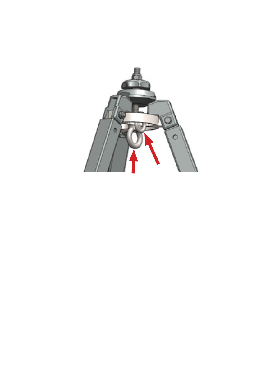
6. Anschlagpunkt nach EN 795
Der Anschlagpunkt (große Öse) Pos. 3
(Abb. 11) ist für das Anschlagen der ver-
wendeten Teilsysteme der PSAgA mit Fall-
dämpferelement z.B. nach EN 354/355, EN
360 und maximal 2 IKAR-Umlenkrollen für
IKAR-HRA Geräte nach EN 1496 geeignet.
Pos. 3
Pos. 6
HRA-Gerät
öffnen
Schließen
Drehrichtungen
Distanzhülse
Position HRA 9,5/12
Position HRA 24/ 33/ 42
Position HRA 15/18
Sicherungsleiste
DEUTSCH

10 11
8. Mögliche Anwendungsvarianten zur Sicherung von 2-3 Personen gegen Absturz und zur
Rettung in Verbindung mit dem zusätzlichen Anschlagpunkt Pos.2
Abb.17:
Eine Personen steigt z. B. in einen Schacht, angeschlagen an einem Höhensicherungsgerät Typ HRA, über den
Anschlagpunkt Pos.1, an der Auffangöse seines Auffanggurtes (Gebrauchsanleitung der Gerätschaften sind zu
beachten). Der Sicherungsposten hat die Möglichkeit, z. B. mit einem Höhensicherungsgerät in Verbindung mit
einem Auffanggurt, sich an dem zusätzlichen Anschlagpunkt Pos. 2 zu.
Selbst bei einer Rettung im Notfall ist der Sicherungsposten stets gegen Absturz gesichert. Verletzungen des Siche-
rungspostens oder Beschädigungen an der PSAgA im Falle eines Sturzes in z. B. einen Schacht durch Anprallen an
Kanten oder Gegenständen können nicht ausgeschlossen werden.
Die Anschlageinrichtung Dreibaum Typ AR ermöglicht es im besonderen Rettungsnotfall das ein Retter, als
3 Person, zusätzlich zu gesicherten Sicherungsposten mit angelegtem Auffang-Rettungsgurt und gesichert an
einem 2. Höhensicherungsgerät mit Rettungshubeinrichtung zu einer verunfallten Person in einen engen Raum (z.B.
Schacht, Behälter) absteigt.
Pos. 1
Pos. 2
DEUTSCH

11
1. This stop device has been tested and approved to secure one person against falling and for rescue in accord-
ance with EN 795:2012-10 Type B and to secure three persons against falling and for rescue in accordance
with CEN/TS 16415:2013-04 . If used in combination with the following additionally required equipment: Safety
harnesses compliant with EN 361, IKAR fall arrest devices compliant with EN 360, IKAR HRA fall arrest de-
vices with rescue-lifting equipment compliant with EN 360/EN 1496, it must be ensured that the force exerted
on the user as the fall is arrested is limited to a maximum of 6 kN. The anchorage equipment and fall arrest
devices must only be used for their original intended purpose.
N.B.: The IKAR HRA fall arrest device with rescue-lifting equipment is not included in the scope of delivery.
2. Non-compliance with the instruction manual may result in life-threatening injuries. In the event of a fall, it must
be ensured that the affected person is not left suspended for more than 15 minutes (risk of shock).
3. A rescue plan that takes into account all potential emergencies in work-related scenarios must be in place.
4. The anchorage equipment must only be used by persons who have received the corresponding training
and who hold the respective expertise. Any factors that could impair an individual's physical health must be
eliminated (e.g. alcohol, drugs, medications or circulatory problems)
5. An IKAR HRA fall arrest device with rescue-lifting equipment can only be used to secure one person at a time,
but may be used by multiple persons one after another.
6. For safety reasons, it is essential that the IKAR DB-AR rescue tripod is set up vertically on a stable footing.
Caution: Never use the rescue tripod on oily or otherwise slippery surfaces!
7. The device should be positioned as plumb as possible over the head of the person to be secured in order to
prevent swinging movements as the person is lowered. The type of use should be selected so as to reduce the
risk of a free-fall and to limit the fall height to a minimum. After securing the IKAR HRA fall arrest device in the
mounting bracket on the IKAR rescue tripod and placing the retractable fastener in the deection roller, the end
(karabiner hook) should be attached to the fall arrest eyelet of the safety harness. Make sure that the karabiner
hook works correctly. The safety of the person at work is duly protected.
8. The product label must be checked for legibility and a visual inspection performed for obvious defects on the
anchorage device and its mounted parts prior to every use (according to the list on page 2).
9. If a piece of equipment is damaged or strained by a fall, or there are any doubts as to whether the piece of
equipment is in a safe condition, it must be withdrawn from use immediately! It may only be used again further
to its inspection and written approval by an expert.
10. Depending on the degree of use, but as a minimum once every twelve months, the anchorage device, i.e. the
IKAR rescue tripod and the optional fall arrest device must be inspected by the manufacturer or by persons
who have been trained and authorised by the manufacturer. This inspection must be documented in the test
books also supplied. The effectiveness and durability of the IKAR rescue tripod and the optional IKAR fall
arrest device depend on regular testing.
11. Repairs may only be carried out by the manufacturer.
12. Compliance with DGUV Regulations 112-198 and 112-199 is mandatory.
13. The permissible load on the anchorage device complies with EN 795:2012 for the protection and rescue of one
person and CEN/TS 16415:2013-04 for the protection and rescue of a maximum of three persons.
14. The IKAR DB-AR rescue tripod and the optional IKAR fall arrest device should be protected from the effects
of welding ames and sparks, re, acids, lyes and from extreme temperatures and corrosive environmental
inuences. During transportation, the rescue tripod must be protected from damage resulting from impacts.
15. At least two people are needed to transport the IKAR DB-AR rescue tripod.
16. Modications or enhancements must not be made to the device, otherwise life-threatening injuries may result.
Before the equipment is put into operation, the instruction manual must be read and understood in its
entirety
The technical data and the associated instruction manual (enclosed) for the IKAR HRA fall arrest device with
rescue-lifting equipment must be observed!
2. Safety instructions
3. Technical data for the DB-AR type rescue tripod
Maximum load: 3 persons
Height-adjustable range: 1.13 m - 1.78 m Set-up
diameter: 0.99 - 1.55 m
Device weight: 28 kg without IKAR HRA
Maximum lifting capacity 300 kg
ENGLISH

12 13
0299
Richtlinie/Directive 2006/42/EG
46000005054
IKAR GmbH
36041 Fulda/GERMANY
www.ikar-gmbh.de
Dreibaum DB-AR
EN 795 Typ B:2012-10,
CEN/TS 16415:2013-04
Serien Nr.: 38/09-2016
Herstelldatum: 09-2016
Max. Belastung: 3 Personen
Max. Tragkraft: 300 kg
0299
Abb. 1
IKAR GmbH
D 36041 Fulda
Abb. 2
Halterung HRA 9,5-33/42
Bestandteil
Dreibaum Typ DB - A1/ A2/ AR
Baujahr : 03/2015
Fabrik-Nr.: 123457
1
2
3
4
5
6
7
8
9
10
21
11
1
2
3
4
5
6
7
8
9
10
11
12
2017
2016
1
2
3
4
5
6
7
8
9
10
11
21
1
2
3
4
5
6
7
8
9
10
11
12
2017
2016
Type plate
Manufacturer Follow the
instruction manual
at all times
Date of manufacture
Serial number
Inspection tag
Type designation
Supervisory body
Permissible load
Bestandteil
Dreibaum DB - A1/A2/AR
Baujahr : 03/2015
Fabrik-Nr.: 123458
0299
Umlenkrolle / Deflection roller
max. Belastung: / max. load:
1 Person
IKAR GmbH
D 36041 Fulda
1
2
3
4
5
6
7
8
9
10
11
12
1
2
3
4
5
6
7
8
9
10
11
12
2017
2016
Fig. 3
Illustration (Fig. 4) shows the
unit with the part: Mounting
bracket for IKAR HRA equipment
Castors
Brace
Locking
bolt
* HRA mounting
bracket
Swivelling and
lockable cross struts
* = Part accessory
Steerable/braking
castors
Folding steering
handle
Captivating pin
per leg
Type plate
Anchorage point
for eyelets
Washer
Clamp nut
Eyelet
4. Overview Fig. 4
Item 13
Item 2
Item 1
Item 7
Item 6
Item 14
Item 8
Item 5
Item 4
Item 3
Item 9
Item 11
Item 10
Socket pin
Item 12
ENGLISH

13
Fig. 5
Abb. 6
1
Fig. 6
Fig. 9
Fig. 10
Fig. 8
Fig. 7
5. Preparing the rescue tripod for use:
Set up the rescue tripod vertically and
release the clamp nut Item 1 by turning it
anti-clockwise. It must be possible to move the
washer Item 2 freely upwards. (Fig. 5)
N.B.: The rescue tripod (Fig. 5) does not have
a
stable footing when standing on its castors.
Fold the legs out sideways, starting with the
leg to which the steering handle is attached.
Open the Velcro straps and fold out the cross
struts Item 7 into a horizontal position, pull
out the locking bolt Item 14, Fig. 6) on the
mushroom-type knob and insert the cross
strut. Release the mushroom-type knob. The
locking bolt locks into place. Check that the
cross strut is locked correctly. Repeat this
procedure for the other two cross struts Turn
the head of the clamp nut counter-clockwise to
screw it rmly against the washer (Fig. 7). This
secures the legs in place.
To position the individually extendible telesco-
pic legs at the corresponding height, rst press
the socket pin down with your thumb Item 12
(Fig. 10) to release it and pull it out.
Extend the telescopic legs to the desired
length and then secure them again using the
socket pin (Item 12). The legs can be exten-
ded to different lengths to compensate for an
uneven ground surface. Repeat this procedure
for the two other telescopic legs. When fully
extended, the telescopic legs automatically
lock into the limit stop via a captivating pin.
To retract the legs, push the captivating pin
back in.
Then align and set up the rescue tripod.
For additional safety, always pull the brace
supplied Item 13 (Fig. 9) through the lower
eyelets Item 10 and pull it tight.
N.B.: If the folding steering handle Item 8 (Fig.
9) is folded out, the castor brake is applied
automatically. This is also the case when the
steering handle is folded in. To disassemble
the DB-AR castor tripod, perform the above
steps in the reverse order.
Possible position
2. Mounting
bracket for IKAR
HRA equipment
Brace
2
1
ENGLISH

14 15
M 10 x 75
M 8 x 40
Fig. 13
Fig. 12
Fig. 11
Fig. 15
Fig. 14
Fig. 16
Top
7. Optional equipment:
IKAR HRA fall arrest device with rescue-lift-
ing equipment
The IKAR HRA fall arrest device with the
rescue-lifting equipment is secured to the
leg on which the type plate is afxed via the
mounting bracket.
To do so, attach the mounting bracket Item
6 (Fig. 12, 13 and 14) to the leg so that the
safety supervisor can operate the rescue
winch of the IKAR HRA device easily in the
event of a rescue. The correct clamping
tension of the mounting bracket is achieved
by the length (45.8 mm) of the spacer sleeves
(also supplied). The tightening torque of the
hexagon socket bolts of quality class 8.8 M
10x75 is 49 Nm. The locking bar should be
positioned according to the device size. The
tightening torque of the cylinder head screws
of quality class 8.8 M 8 x 40 is 20 Nm. Insert
the IKAR HRA device into the mounting
bracket. The IKAR HRA device is secured to
the mounting bracket via the socket pin
N.B.: Use IKAR mounting brackets only.
Only IKAR equipment should be attached
to IKAR mounting brackets.
Deection roller with karabiner hook:
The deection roller (Fig. 15+16) is used to
guide and deect the steel rope of the IKAR
HRA fall arrest device.
Open the closed deection roller (Fig. 15) by
twisting the two plates (Fig. 16) and insert the
steel rope into the guide groove. Then twist
the two plates back into their original closed
position.
Attach the snap hook to the deection roller
and hook it into the anchorage point Item 3 of
the rescue tripod.
Caution: Use steel karabiner hooks that
comply with EN 362 Class B only.
Tighten the screw retention nut on the
karabiner hook. Check the pulley for ease of
movement
N.B.: The IKAR HRA device retracts the line
automatically if the rescue lifting function is not
engaged.
6. Anchorage point in accordance with
EN 795
The anchorage point (large eyelet) Item 3 (Fig. 11) is
suitable for anchoring the deployed subsystems of the
fall arrest shock absorbing device of the personal protec-
tive equipment e.g. in accordance with EN 354/355, EN
360 and a maximum of two IKAR deection rollers for
IKAR-HRA devices in accordance with EN 1496.
Item 3
Item 6
HRA device
Open
Close
Directions
Spacer sleeve
Item HRA 9.5/12
Item HRA 24/33/42
Item HRA 15/18
Locking bar
ENGLISH

15
8. Possible application scenarios to protect 2-3 persons from falling and for rescue in
combination with the additional anchorage point Item 2
Fig.17:
A person enters a shaft, for example attached to an HRA type fall arrest device by the fall arrest eyelet of his safety
harness via the anchorage point Item 1 (see the instruction manual for the specic equipment). The safety supervisor
has the option, for example, to use a fall arrest device in combination with a safety harness for attachment to an
additional anchorage point Item 2.
Even during an emergency rescue, the safety supervisor is always protected from falling. It is not possible to rule out
the possibility of injury to the safety supervisor, or damage to the personal protective equipment resulting from an
impact with edges or objects in the event of a fall into a shaft, for example.
In a special rescue emergency, the AR type rescue tripod anchorage device allows a rescuer, as a third person, to
rappel to an injured person in a conned space
(e.g. shaft, container) in addition to a safety supervisor secured by an attached safety harness/lifebelt and secured to
a second fall arrest device with rescue-lifting equipment.
Item 1
Item 2
ENGLISH

16 17
1. Ce dispositif d’ancrage a été testé et homologué pour la sécurisation d’une personne selon EN 795:2012-10
Type B et pour la sécurisation de 3 personnes selon CEN/TS 16415:2013-04 aux ns de sécurité antichute et
de sauvetage. Avec les harnais selon la norme EN 361 nécessaires en complément, [les dispositifs antichute
IKAR selon EN 360,] les dispositifs antichute IKAR du type HRA avec système de secours selon EN 360 / EN
1496 ne doivent en aucun cas exercer sur l’utilisateur pendant le sauvetage une force supérieure à 6 kN au
maximum. Le dispositif d'ancrage et les dispositifs antichute doivent être utilisés uniquement conformément à
leur destination.
Remarque : Le dispositif antichute IKAR de type HRA avec système de secours n'est pas fourni.
2. Il existe un danger de mort en cas d'inobservation des instructions d'utilisation. En cas de chute, exclure
impérativement de laisser la personne accidentée en suspension pendant plus de 15 minutes (risque de choc).
3. Garder à disposition un plan des mesures de secours dans lequel sont examinées toutes les situations
d’urgence potentielles pendant le travail.
4. Le dispositif d’ancrage doit être employé uniquement par des personnes formées en conséquence et disposant
des compétences nécessaires. Tout problème de santé doit être exclu (par ex. alcoolisme, toxicomanie, effets
de médicaments ou problèmes cardiovasculaires).
5. Lorsqu'il est utilisé, un dispositif antichute IKAR de type HRA avec système de secours ne peut assurer qu'une
personne. Il peut toutefois être utilisé par plusieurs personnes à la suite.
6. An de garantir la sûreté du dispositif, le trépied IKAR DB-AR doit être installé verticalement et de manière
stable. Attention : Ne jamais utiliser le trépied sur des sols tachés d’huile ou glissants pour d’autres raisons.
7. Le dispositif doit être alors disposé le plus possible à la verticale de la tête de la personne à sécuriser, an
d'exclure tout effet de balancier en cas de chute. Le mode d’utilisation doit être choisi de façon à réduire au
minimum la chute libre et la hauteur de chute. Après avoir xé le dispositif antichute IKAR de type HRA dans sa
xation sur le trépied IKAR et inséré le connecteur amovible dans la poulie de renvoi, l’extrémité du dispositif
(mousqueton) doit être attachée sur la boucle de retenue du harnais. Vérier le fonctionnement parfait du
mousqueton. La sécurité de la personne en intervention est assurée.
8. Avant chaque utilisation, contrôler la lisibilité du ou des marquages du produit et effectuer un contrôle visuel du
dispositif d’ancrage et de ses composants à la recherche de défauts visibles (selon la liste fournie p. 2).
9. Si l’équipement est endommagé ou a été sollicité par une chute, ou en cas de doute sur son état de sécurité,
il doit être immédiatement retiré du circuit. Il ne peut être réutilisé qu’après avoir été contrôlé par un spécialiste
des systèmes antichute personnels et sa réutilisation validée par autorisation écrite.
10. Le point d'ancrage (c’est-à-dire le trépied IKAR et le dispositif antichute en option) doit être contrôlé par le fa-
bricant ou par des spécialistes formés et agréés par le fabricant en fonction des contraintes qu’il a subies, mais
de toute façon tous les douze mois au minimum. Cette opération doit être documentée dans les carnets de
contrôle fournis. L’efcacité et la longévité du trépied IKAR et du dispositif antichute IKAR en option dépendent
de ce contrôle régulier.
11. Seul le fabricant peut procéder aux réparations.
12. Les règles DGUV 112-198 et 112-199 doivent être respectées.
13. La charge admissible du point d’ancrage correspond aux normes EN 795:2012 type B pour la sécurité et le
sauvetage d’une personne et CEN/TS 16415:2013-04 pour la sécurité de 3 personnes au maximum.
14. Il convient de protéger le trépied IKAR DB-AR ainsi que le dispositif antichute en option des effets des ammes
et étincelles de soudage, du feu, des acides, des bases et des températures extrêmes, ainsi que des agents
environnementaux corrosifs. Le trépied ne doit pas être endommagé par des chocs pendant son transport.
15. Deux personnes au minimum sont nécessaires pour transporter le trépied IKAR DB-AR.
16. Le dispositif ne doit subir aucune modication ni ajout, sous peine d’engendrer un danger de mort.
Avant la mise en service, le mode d'emploi doit être intégralement lu et son contenu compris.
Respecter impérativement les paramètres techniques et le mode d’emploi ci-joint du système antichute IKAR
HRA avec système de secours.
2. Mode d'emploi sur le plan de la sécurité
3. Caractéristiques techniques du trépied de type DB-AR
Charge max. : 3 personnes
Plage de réglage de la hauteur : 1,13 m à 1,78 m
Diamètre installé : 0,99 à 1,55 m
Poids de l’appareil : 28 kg sans IKAR HRA
Capacité de charge max. : 300 kg
FRANÇAIS

17
0299
Richtlinie/Directive 2006/42/EG
46000005054
IKAR GmbH
36041 Fulda/GERMANY
www.ikar-gmbh.de
Dreibaum DB-AR
EN 795 Typ B:2012-10,
CEN/TS 16415:2013-04
Serien Nr.: 38/09-2016
Herstelldatum: 09-2016
Max. Belastung: 3 Personen
Max. Tragkraft: 300 kg
0299
Abb. 1
IKAR GmbH
D 36041 Fulda
Abb. 2
Halterung HRA 9,5-33/42
Bestandteil
Dreibaum Typ DB - A1/ A2/ AR
Baujahr : 03/2015
Fabrik-Nr.: 123457
1
2
3
4
5
6
7
8
9
10
21
11
1
2
3
4
5
6
7
8
9
10
11
12
2017
2016
1
2
3
4
5
6
7
8
9
10
11
21
1
2
3
4
5
6
7
8
9
10
11
12
2017
2016
Plaque signalétique
Fabricant Consulter le
mode d’emploi
Date de fabrication
Numéro de série
Plaquette de contrôle
Type
Service de
surveillance
Charge
admissible
Bestandteil
Dreibaum DB - A1/A2/AR
Baujahr : 03/2015
Fabrik-Nr.: 123458
0299
Umlenkrolle / Deflection roller
max. Belastung: / max. load:
1 Person
IKAR GmbH
D 36041 Fulda
1
2
3
4
5
6
7
8
9
10
11
12
1
2
3
4
5
6
7
8
9
10
11
12
2017
2016
Fig. 3
L’illustration (Fig. 4) représente
le dispositif équipé de la xation
pour les antichutes IKAR HRA
Roulettes
Sangle de
retenue
Boulon de
verrouillage
* Fixation du
HRA
Traverses pivotantes
et verrouillables
* = Accessoire
Roulette dirigée et
freinée
Timon à main
escamotable
Goupille d’arrêt
pour chaque pied
Plaque
signalétique
Point d’ancrage des
anneaux
d’attache
Rondelle
conique
Écrou étoile
Anneau d’attache
4. Vue d'ensemble Fig. 4
rep. 13
rep. 2
rep. 1
rep. 7
rep. 6
rep. 14
rep. 8
rep. 5
rep. 4
rep. 3
rep. 9
rep. 11
rep. 10
Goujon à broche
rep. 12
FRANÇAIS

18 19
Fig. 5
Abb. 6
1
Fig. 6
Fig. 9
Fig. 10
Fig. 8
Fig. 7
5. Instauration de la disponibilité opérationnelle :
Installer le trépied verticalement et desserrer
l’écrou étoile (rep. 1) en le tournant dans le
sens antihoraire. La rondelle conique (rep. 2)
doit pouvoir remonter librement. (Fig. 5)
Remarque : Le trépied (Fig. 5) n’est pas stable
par son propre poids sur les roulettes.
Déployer les pieds, en commençant par
celui auquel est xé le timon à main. Ouvrir
les bandes auto-agrippantes et déplier les
traverses (rep. 7) à l’horizontale. Soulever
le boulon de verrouillage (rep. 14, Fig. 6) en
tirant sur la poignée champignon et mettre
la traverse en place. Relâcher la poignée
champignon. Le boulon de verrouillage
s’enclenche. Vérier le verrouillage de la
traverse. Procéder de la même manière avec
les 2 autres traverses. Tourner l’écrou étoile
dans le sens horaire pour le serrer contre la
rondelle conique (Fig. 7). Les pieds sont ainsi
solidement xés.
Pour régler les pieds télescopiques individuel-
lement à la hauteur appropriée, débloquer
d'abord le goujon à broche (rep. 12, Fig. 10)
en appuyant avec le pouce et le retirer.
Allonger les pieds à la longueur souhaitée
puis les sécuriser avec le goujon à broche
(rep. 12). Pour compenser d'éventuelles
irrégularités du sol, il est possible d’allonger
chaque pied à une longueur différente.
Répéter l'opération pour les deux autres pieds
télescopiques Allongés à la longueur maxi-
male, les pieds télescopiques s’enclenchent
automatiquement en n de course grâce à
une goupille de blocage. Il suft d’enfoncer
celle-ci pour les rétracter.
Ajuster et installer ensuite le trépied. Pour
plus de sûreté, toujours passer la sangle de
retenue (rep. 13, Fig. 9) dans les anneaux
d’attache inférieurs (rep. 10) et la tendre.
Remarque : Quand le timon à main (rep. 8,
Fig. 9) est déployé, la roulette est automati-
quement freinée. Elle l’est également quand
il est rabattu. Pour le démontage du trépied
sur roulettes DB-AR, procéder dans l’ordre
inverse.
position
possible,d’une
deuxième xation
pour des anti-
chutes IKAR HRA
Sangle de retenue
2
1
FRANÇAIS
19
M 10 x 75
M 8 x 40
Fig. 13
Fig. 12
Fig. 11
Fig. 15
Fig. 14
Fig. 16
haut
7. Composants en option :
Antichute IKAR type HRA avec système de
secours
L'antichute IKAR type HRA avec système de
secours est xé au moyen du support au pied
sur lequel la plaque signalétique est apposée.
Pour ce faire, monter le support (rep. 6,
Fig. 12, 13 et 14) sur le pied de sorte que
l’équipe de sauvetage puisse, en cas
d'opération de secours, se trouver dans une
position ergonomique favorable pour utiliser la
manivelle de secours de l’antichute IKAR HRA
sans difcultés. La bonne tension de serrage
du support est atteinte grâce à la longueur
(45,8 mm) des entretoises fournies. Appliquer
un couple de serrage de 49 Nm aux vis à tête
hexagonale de classe de qualité 8.8 M10x75.
La barrette de xation doit être positionnée en
fonction de la taille des appareils. Appliquer
un couple de serrage de 20 Nm aux vis à tête
cylindrique de classe de qualité 8.8 M8x40.
Mettre en place l'appareil IKAR HRA dans le
support. L’antichute IKAR HRA est sécurisé au
moyen du boulon à broche et du support.
Attention : Utiliser uniquement des
supports IKAR pour le montage. Monter
uniquement des appareils IKAR sur les
supports IKAR.
Poulie de renvoi avec mousqueton :
La poulie (Fig. 15 et 16) sert à guider et à
renvoyer le câble en acier de l'antichute IKAR
type HRA.
Pour cela, ouvrir la poulie fermée (Fig. 15)
en faisant tourner les deux asques l’un par
rapport à l’autre (Fig. 16) et introduire le câble
en acier dans la gorge de la poulie. Ramener
ensuite les deux asques à leur position
initiale.
Accrocher le mousqueton à la poulie de
renvoi et le xer au point d'ancrage du trépied
(rep. 3).
Attention : Utiliser exclusivement un
mousqueton en acier suivant la norme
EN 362 classe B.
Serrer fortement la vis de blocage sur le
mousqueton. Vérier la souplesse de fonction-
nement de la poulie
Remarque : L’antichute IKAR HRA enroule
automatiquement le câble tant que la fonction
de palan de sécurité n’est pas enclenchée.
6. Point d’ancrage selon EN 795
Le point d’ancrage (grand anneau, repère 3 dans la
Fig. 11) convient pour accrocher les sous-systèmes
utilisés du dispositif antichute personnel avec élément
amortisseur d’énergie, par ex. selon EN 354/355 et
EN 360, et au maximum 2 poulies de renvoi IKAR
pour antichutes IKAR-HRA selon EN 1496.
rep. 3
rep. 6
Appareil HRA
Ouvrir
Fermer
Sens de rotation
Entretoise
Position pour HRA 9.5 / 12
Position pour HRA 24 / 33 / 42
Position pour HRA 15 / 18
Barrette de xation
FRANÇAIS
20 21
8. Variantes d'application possibles pour la sécurisation de 2-3 personnes contre la chute et
pour le sauvetage associé à un point d’ancrage supplémentaire (repère 2).
Fig. 17 :
Une personne monte, par exemple dans une cage, ancrée à l'aide du dispositif de protection antichute de type HRA,
avec un point d’ancrage (rep. 1) sur la boucle de retenue de son harnais (suivre les instructions des équipements).
L’équipe de sauvetage a la possibilité de s'assurer sur le point d'ancrage supplémentaire (rep. 2), par exemple avec
un dispositif antichute associé à un harnais.
Même lors d'une opération de sauvetage en cas d'urgence, l’équipe de sauvetage est protégée contre les chutes. Il
n'est pas possible d'écarter le risque que l'EPI soit endommagé en cas de chute par heurt contre des arêtes ou des
objets.
Au cours d’une opération de sauvetage d’urgence, le trépied d'ancrage de type AR permet à un autre sauveteur
équipé d'un harnais de sauvetage de s’assurer avec un deuxième dispositif antichute avec système de secours et
de descendre avec le premier sauveteur assuré (3ème personne) jusqu'à la personne accidentée, dans un espace
restreint (par exemple cage, réservoir).
rep. 1
rep. 2
FRANÇAIS
Table of contents
Languages:
Other IKAR Camera Accessories manuals


