IKEA ADRATT User manual

ADRÄTT

2 AA-2194876-2
FOR YOUR SAFETY: Do not store or use gasoline or other ammable
vapors and liquids in the vicinity of this or any other appliance.
United States
and Canada
INSTALLATION AND SERVICE MUST BE PERFORMED
BY A QUALIFIED INSTALLER.
IMPORTANT: SAVE FOR LOCAL ELECTRICAL INSPECTOR'S USE.
READ AND SAVE THESE INSTRUCTIONS FOR FUTURE REFERENCE.
Your safety and the safety of others are very important.
We have provided many important safety messages in this manual and on your appliance. Always read
and obey all safety messages.
This is the safety alert symbol.
This symbol alerts you to potential hazards that can kill or hurt you and others.
All safety messages will follow the safety alert symbol and either the word "WARNING" or
"CAUTION."
Indicates a potentially hazardous situation which, if not
avoided, may result in death or serious injury.
Indicates a potentially hazardous situation which, if not
avoided, may result in minor or moderate injury.
All safety messages will tell you what the potential hazard is, tell you how to reduce the chance of injury,
and tell you what can happen if the instructions are not followed.
CAUTION!
WARNING!
Tip Over Hazard
Electric Shock Hazard
Disconnect power before servicing.
Use 12-gauge solid copper wire.
Electrically ground oven.
Failure to follow these instructions can result
in death, re, or electrical shock.
Tip Over Hazard
• A child or adult can tip the oven
and be killed.
• Install the anti-tip device to oven
and/or structure per installation
instructions.
• Ensure the anti-tip device is re-engaged when the
oven is moved.
• Do not operate the oven without the anti-tip device
in place and engaged.
• Failure to follow these instructions can result in
death or serious burns to children and adults.
Refer to the installation
instructions supplied with your
appliance for proper installa-
tion.
Check for proper installation
with a visual check that the
anti-tip screws are present.
Test the installation with light
downward pressure on the
open oven door. The oven
should not tip forward.
Anti-tip mounting holes
WARNING!
NOTE: Your new wall oven has been designed
to t a limited variety of cutout sizes to make
the job of installing easier. The rst step of
your installation should be to measure your
current cutout dimensions and compare them
to the cutout dimensions chart below for your
model. You may nd little or no cabinet work
being necessary.

3

4 AA-2194876-2
Tools You Will Need
For leveling legs and Anti-Tip Bracket:
• Adjustable wrench or channel lock pliers
• 5/16”Nutdriver or Flat Head Screwdriver
• Electric Drill & 1/8” Diameter Drill Bits
(Masonry Drill Bit 3/16” if installing in concrete)
• Spirit level
• Tape measure
Additional Materials You Will Need:
• Power Supply Cord or
• Copper Electrical Wiring & Metal Conduit (for
hard wiring)
Important notes to the installer
1. Read all instructions contained in these
installation instructions before installing the wall
oven.
2. Remove all packing material from the oven
compartments before connecting the electrical
supply to the wall oven.
3. Observe all governing codes and ordinances.
4. Be sure to leave these instructions with the
consumer.
5. Remove oven door to facilitate installation. See
the User manual for instructions.
6. THESE OVENS ARE NOT APPROVED FOR
STACKABLE OR SIDE-BY-SIDE INSTALLATION.
7. All materials used in construction of cabinets,
enclosures, and supports surrounding the
product must have a temperature rating above
194°F (90°C).
Important notes to the consumer
Keep these instructions with your User manual
for the local electrical inspector's use and future
reference.
• Be sure your wall oven is installed and grounded
properly by a qualied installer or service
technician.
• This wall oven must be electrically grounded in
accordance with local codes or, in their absence,
with the National Electrical Code ANSI/NFPA
No.70- latest edition in United States, or with
CSA Standard C22.1, Canadian Electrical Code,
Part 1, in Canada.
IMPORTANT SAFETY
INSTRUCTIONS
If the information in this manual is not
followed exactly, a re or electrical shock
may result causing property damage,
personal injury or death.
WARNING!
2x
1x
4x
Stepping, leaning or sitting on the door of this
wall oven can result in serious injuries and can
also cause damage to the wall oven.
Never use your wall oven for warming or
heating the room. Prolonged use of the wall
oven without adequate ventilation can be
dangerous.
The electrical power to the oven must be shut off
while line connections are being made. Failure to
do so could result in serious injury or death.
WARNING!

5
PRODUCT DIMENSIONS
MODEL A B C D
30" (76.2 cm) 30 (76.2) 29 (73.7) 281/4(71.8) 243/4(62.9)
*267/8 (68.24) with door handle
CUTOUT DIMENSIONS AND CABINET WIDTH
FG (Min.) H. Standard Height
(**Others, see note 4) IJ
MODEL Min. Max. Min. Max.
30" (76.2 cm) 281/2(72.4) 29 (73.7) 24 (61.0) 27¼ (69.2) 281/8(71.4) 301/8 (76.5) Min 281/2 (72.4)
Figure 1
30" Single Wall Ovens
All dimensions are in inches (cm).
NOTES:
1. Base must be capable of supporting
200 pounds (90 kg).
2. Allow at least 21" (53.3 cm) clearance in front
of oven for door depth when it is open.
Printed in U.S.A.
2" (5 cm) Wide Wood
Spacer if Needed
B
B
A
A
D
D
C
C
H
H
F
F
I
I
G
G
27 1/4”
(69.2 cm)
1 1/2”
1 1/2”
(3.8 cm)
(3.8 cm)
Min
Min
31”*
(78.7 cm)
31”*
(78.7 cm)
3”
(7.6 cm)
3”
(7.6 cm)
J
J
Door Open
(see note 2) Spacer
Hole
for
Cord
Electrical
Junction Box
SINGLE WALL OVEN - SINGLE INSTALLATION
Do not remove spacers (if equipped) on the side walls of the built-in oven. These spacers
center the oven in the space provided. The oven must be centered to prevent excess heat
buildup that may result in heat damage or re.
WARNING!
3. Dimension G (cutout depth) is
critical to the proper installation of
the built-in oven. If the oven trim
does not butt against the cabinet,
or if noise is heard on convection
models, verify dimension G to
assure it is the required depth.
4.For a cutout height greater
than the maximum (H),
add one 2" (5 cm) wide
wood shim of appropriate
height to each side of the
opening under the appliance
side rails. You can order a
larger bottom trim through a
Service Center.
Suggested distance from oor is 31" (78.7 cm).
Minimum required distance is 4 ½" (11.4 cm).

6 AA-2194876-2
1. Carpentry
Refer to gure 1 for the dimensions applicable
to your appliance, and the space necessary to
receive the oven. The oven support surface may
be solid plywood or similar material, however the
surface must be level from side to side and from
front to rear.
2. Adjusting Oven Height
Oven height can be adjusted with 2" (5 cm) wide
wood shims when needed to t into an existing
cabinet cutout opening, when cutout height
exceeds 281/4" (71.8 cm) for the single wall oven
(see Figure 1). Place shims of appropriate height
beneath the oven side rails.
3. Electrical Requirements
Each appliance must be supplied with the proper
voltage and frequency, and connected to an
individual, properly grounded branch circuit,
protected by a circuit breaker or fuse. To know the
circuit breaker or fuse required by your model, see
the rating plate to nd the wattage consumption
and refer to Figure 2 to get the circuit breaker or
fuse amperage.
Figure 2
Appliance
Rating
Watts
240V
Protection
Circuit
Recommended
Appliance
Rating Watts
208V
Protection
Circuit
Recommended
Less than
4800W
20A
Less than
4100W
20A
4801W -
7200W
30A
4101W -
6200W
30A
7201W -
9600W
40A or 50A
6201W -
8300W
40A or 50A
9601W and
+
50A
8301W and +
50A
Observe all governing codes and local ordinances.
1. A 3-wire or 4-wire single phase 120/240 or
120/208 Volt, 60 Hz AC only electrical supply
is required on a separate circuit fused on both
sides of the line (red and black wires). A time-
delay fuse or circuit breaker is recommended.
DO NOT fuse neutral (white wire). Only
certain cooktop models may be installed over
certain built-in electric oven models. Approved
cooktops and built-in ovens are listed by
the MFG ID number (see the insert sheet
included in the literature package). Do not
install a cooktop over a side-by-side wall oven
installation.
2. These appliances should be connected to
the fused disconnect (or circuit breaker)
box through exible armored or nonmetallic
sheathed cable. The exible armored cable
extending from the appliance should be
connected directly to the junction box. The
junction box should be located as shown in
Figure 1 and with as much slack as possible
remaining in the cable between the box and
the appliance, so it can be moved if servicing is
ever necessary.
3. A suitable strain relief must be provided
to attach the exible armored cable to the
junction box.
An extension cord should not be used with
this appliance. Such use may result in a re,
electrical shock, or other personal injury. If you
need a longer power cord you can purchase
a 10' (3 m) power cord kit #903056-9010 by
calling the Service Center.
WARNING!
NOTE: Wire sizes and connections must conform
with the fuse size and rating of the appliance in
accordance with the American National Electrical
Code ANSI/NFPA No. 70-latest edition, or with
Canadian CSA Standard C22.1, Canadian Electrical
Code, Part 1, and local codes and ordinances.

7
4. Electrical connection
It is the responsibility and obligation of the
consumer to contact a qualied installer to assure
that the electrical installation is adequate and is
in conformance with the National Electrical Code
ANSI/NFPA No. 70-latest edition, or with CSA
Standard C22.1, Canadian Electrical Code, Part 1,
and local codes and ordinances.
Electrical Shock Hazard
• Electrical ground is required on this appliance.
• Do not connect to the electrical supply until
appliance is permanently grounded.
• Disconnect power to the junction box before
making the electrical connection.
• This appliance must be connected to a
grounded, metallic, permanent wiring system,
or a grounding connector should be connected
to the grounding terminal or wire lead on the
appliance.
• Do not use a gas supply line for grounding the
appliance.
Failure to do any of the above could result in a
re, personal injury or electrical shock.
WARNING!
In cold weather shipping and storage
conditions, make sure that oven is in nal
location at least three (3) hours before
switching on power. Switching on power while
oven is still cold may damage the oven controls.
CAUTION!
Risk of electrical shock (Failure to heed this
warning may result in electrocution or other
serious injury.) This appliance is equipped with
copper lead wire. If connection is made to
aluminum house wiring, use only connectors
that are approved for joining copper and
aluminum wire in accordance with the National
Electrical Code and local code and ordinances.
When installing connectors having screws
which bear directly on the steel and/or
aluminum exible conduit, do no tighten screws
sufciently to damage the exible conduit. Do
not over bend or excessively distort exible
conduit to avoid separation of convolutions en
exposure of internal wires.
WARNING!
DO NOT ground to a gas supply pipe. DO NOT
connect to electrical power supply until appliance
is permanently grounded. Connect the ground wire
before turning on the power.
(If your appliance is equipped with a white
neutral conductor.)
This appliance is manufactured with a white
neutral power supply and a frame connected
copper wire. The frame is grounded by
connection of grounding lead to neutral lead at
the termination of the conduit, if used in USA,
in a new branch circuit installation (1996 NEC),
mobile home, recreational vehicles, where
local code do not permit grounding through the
neutral (white) wire or in Canada, disconnect
the white and green lead from each other and
use ground lead to ground unit in accordance
with local codes, connect neutral lead to branch
circuit-neutral conductor in usual manner see
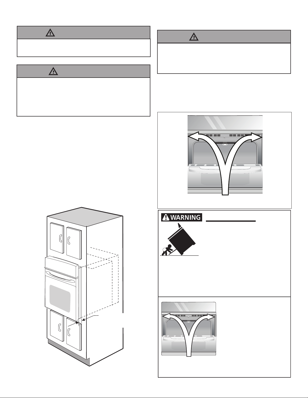
Figure 4. If your appliance is to be connected
to a 3 wire grounded junction box (US only),
where local code permit connecting the
appliance-grounding conductor to the neutral
(white) see Figure 3.
WARNING!

8 AA-2194876-2
NOTE TO ELECTRICIAN: The armored cable leads
supplied with the appliance are UL-recognized for
connection to larger gauge household wiring. The
insulation of the leads is rated at temperatures
much higher than temperature rating of household
wiring. The current carrying capacity of the
conductor is governed by the temperature rating
of the insulation around the wire, rather than the
wire gauge alone.
Figure 3
3-WIRE GROUNDED JUNCTION BOX
Cable from Power Supply
Black
Wires
Junction
Box
Ground Wire
(Bare or Green
Wire)
White Wire
(Neutral)
U.L.-Listed Conduit
Connector (or CSA
listed)
Red
Wires
White Wire
(Neutral)
Cable from appliance
Where local codes permit connecting the
appliance-grounding conductor to the neutral
(white) wire (US Only) (see gure 3):
1. Disconnect the power supply.
2. In the junction box:
connect appliance and power supply cable wires
as shown in Figure 3.
Model and Serial Number Location
The rating plate is located along the interior side
trim of the oven and visible when the door is
opened.
When ordering parts for or making inquires about
your oven, always be sure to include the model
and serial numbers and a lot number or letter
from the rating plate on your oven.
Single Wall Oven
Rating Plate Location
If oven is used in a new branch circuit installation
(1996 NEC), mobile home, recreational vehicle,
or where local codes DO NOT permit grounding
through the neutral (white) wire, the appliance
frame MUST NOT be connected to the neutral wire
of the 4-wire electrical system. (see gure 4):
1. Disconnect the power supply.
2. Separate the green (or bare copper) and white
appliance cable wires.
3. In the junction box:
connect appliance and power supply cable wires
as shown in Figure 4.
Cable from Power Supply
White Wire
Junction Box
White Wire
Black
Wires
Red
Wires
Ground Wire
Ground Wire
(Bare or Green
Wire)
U.L.-Listed Conduit
Connector (or CSA
listed)
Figure 4
4-WIRE GROUNDED JUNCTION BOX
Cable from appliance

9
Anti-Tip Mounting Holes
Figure 6
Tip Over Hazard
• A child or adult can tip the oven
and be killed.
• Install the anti-tip device to oven
and/or structure per installation
instructions.
• Ensure the anti-tip device is re-engaged when the
oven is moved.
• Do not operate the oven without the anti-tip device
in place and engaged.
• Failure to follow these instructions can result in
death or serious burns to children and adults.
Refer to the installation
instructions supplied with your
appliance for proper installa-
tion.
Check for proper installation
with a visual check that the
anti-tip screws are present.
Test the installation with light
downward pressure on the
open oven door. The oven
should not tip forward.
Anti-tip mounting holes
5. Cabinet Installation
Figure 5
1½" (3.8 cm)
clearance
between unit
1. Unpack the wall oven. Remove the bottom trim
taped on the oven top panel.
2. Find the 2 anti-tip mounting screws included in
the literature package.
3. Insert the oven into the cabinet opening. Slide
oven inward leaving 1½" (3.8 cm) clearance
between the oven and front of cabinet (see
Figure 5).
4. Pull the armored cable through the hole for it in
the cabinet and toward the junction box while
moving the appliance inward.
5. Push the oven in and against the cabinet.
Do not lift or manipulate the oven by the door
handle or the control panel.
IMPORTANT!
Heavy Weight Hazard
• Use 2 or more people to move and install wall
oven.
• Failure to follow this instruction can result in
injury or damage to the unit.
WARNING!
The wall oven can tip when the door is open.
The anti-tip mounting screws supplied with the
wall oven must be installed to prevent tipping of
the wall oven and injury to persons.
WARNING!
6. Install the Anti-tip Mounting
Screws
A. The mounting holes in the side trims may
be used as a template to locate the appliance
mounting screw holes (see gure 6).
B. Use the two screws supplied to x the
appliance to the cabinet.

10 AA-2194876-2
A
B
A
B
Figure 7
Screws to attach the bottom trim are supplied with
the oven. The trims are easier to install if the door
is removed. See the User manual for instructions on
how to remove the oven door.
A. Place the air diverter (A) in place as shown
in Figure 7. Line up screw locations and attach
both ends.
B. Place the color matched trim (B) in place as
shown. Line up screw locations and attach both
ends.
7. Install the Bottom Trim
Bottom trims must be installed for the oven to
function properly. DO NOT operate the oven
without bottom oven trims installed. Do not use
wood or any other trim that is not manufactured
for use with this model. Operating the appliance
without manufacturer's bottom trims properly
installed may cause personal injury and may
damage cabinetry or the appliance.
CAUTION!

11
Only certain cooktop models may be installed over
certain built-in electric oven models. Approved cooktops
and built-in ovens are listed by the MFG ID number
and product code (see the insert sheet included in
G
F
H
35¾” Min.
(90.8 cm) Min.
Use 3/4” (1.9 cm) plywood, installed
on two runners, ush with toe plate.
Base must be capable of supporting
200 pounds (90 kg).
Cut an opening in wood base minimum
9” x 9” (23 X 23 cm), 2” (5 cm) from left
side ller panel, to route armored cable to
junction box.
208/240 Volt junction
box for built-in oven.
Figure 8 - TYPICAL UNDER COUNTER INSTALLATION OF A SINGLE ELECTRIC BUILT-IN
OVEN WITH AN ELECTRIC COOKTOP MOUNTED ABOVE
Approx. 3”
(7.5 cm)
Cabinet side ller panels
are necessary to isolate the
unit from adjoining cabinets.
Cabinet side ller height
should allow for installation
of approved cooktop models
5” (12.7 cm) Max.
CUTOUT DIMENSIONS AND CABINET WIDTH
F. WIDTH G. DEPTH H. HEIGHT
30" (76.2 cm) 281/2" (72.4 cm) Min.
29" (73.7 cm) Max. 24 (61.0) 271/4(69.2) Min.
281/8 (71.4) Max.
TYPICAL UNDER-COUNTER INSTALLATION
Do not remove spacers (if equipped) on the side walls of the built-in oven. These spacers
center the oven in the space provided. The oven must be centered to prevent excess heat
buildup that may result in heat damage or re.
To reduce the risk of personal injury and tipping of the wall oven, the wall oven must be
secured to the cabinet (s) by mounting screws.
WARNING!
the literature package and cooktop
installation instructions
for dimensions). Do
not install a side-by-
side conguration
under countertops, or
in combination with a
cooktop.

12 AA-2194876-2
Figure 9 - TYPICAL UNDER COUNTER INSTALLATION OF A SINGLE ELECTRIC BUILT-IN OVEN
WITH A GAS COOKTOP ABOVE
18”(45.7 cm) Max.
6 1/2” Min.
(16.5 cm)
Flare
Union
4”(10 cm)
120V/60Hz
Grounded
Outlet
Right Side
of Cabinet
(To be
accessible
for shut-
off valve
operation)
Pressure
Regulator
Manual
Shutoff
Valve
Flexible Appliance Conduit
Cabinet sides
or ller panel
Wall Oven Cabinet
5” Max.
(12.7 cm)
Flare
Union
9. Checking Operation
Your model is equipped with an Electronic Oven
Control. Each of the functions has been factory
checked before shipping. However, it is suggested
that you verify the operation of the electronic oven
controls once more. Refer to the User manual for
operation.
1. Remove all items from the inside of the oven.
2. Turn on the power to the oven (Refer to your
User manual.)
3.Verify the operation of the electronic oven
controls:
Bake– Verify that this function makes the oven
hot. 20 seconds after turning oven on, open the
door and you should feel heat coming from the
oven.
Broil– When the oven is set to BROIL, the upper
element in the oven should become red.
Convection–When the oven is set for a
convection baking or roasting, both elements
cycle on and off alternately and the convection
fan will run. The convection fan will stop running
when the oven door is opened.
Before You Call for Service
Read the "Before You Call for Service Checklist"
and the "Operating Instructions" in your User
manual. It may save you time and expense. The
list includes common occurrences that are not the
result of defective workmanship or materials in
this appliance.
Refer to your User manual for service phone
numbers.
IMPORTANT NOTE
A cooling fan inside the upper rear part above
the oven provides cooling of the oven electrical
and electronic components. If the oven has been
operating at high temperatures, the fan will
continue to run after the oven is turned off.
8. Leveling the Wall Oven
1. Install an oven rack in the center of the upper
oven (see Figure 10).
2. Place a level on the rack. Take 2 readings with
the level placed diagonally in one direction
and then the
other. Use
wood shims
under the wall
oven to level if
necessary.
3. If the level
indicates that
the rack is not
level, use wood
shims to reach
a compromise
for both ovens.
Figure 10

13
LA INSTALACIÓN Y EL SERVICIO DEBEN SER EFECTUADOS POR
UN INSTALADOR CALIFICADO. IMPORTANTE: GUARDE ESTAS
INSTRUCCIONES PARA USO DEL INSPECTOR LOCAL DE ELECTRICIDAD.
LEA Y GUARDE ESTAS INSTRUCCIONES PARA REFERENCIA FUTURA.
PARA SU SEGURIDAD: No almanece ni utilice gasolina u otros vapores y
líquidos inamables en la proximidad de este o de cualquier otro artefacto.
ADVERTENCIA!
Su seguridad y la seguridad de los demás son muy importantes.
Hemos proporcionado muchos mensajes de seguridad importantes en este manual y en su
electrodoméstico. Siempre lea y obedezca todos los mensajes de seguridad.
Éste es el símbolo de alerta de seguridad.
Este símbolo lo alerta sobre posibles peligros que pueden matarlo o lastimarlo a usted y
a otros. Todos los mensajes de seguridad seguirán el símbolo de alerta de seguridad y la
palabra "ADVERTENCIA" o "PRECAUCIÓN".
Indica una situación potencialmente peligrosa que, si no se
evita, puede provocar la muerte o lesiones graves.
Indica una situación potencialmente peligrosa que, si no se
evita, puede provocar lesiones leves o moderadas.
Todos los mensajes de seguridad le dirán cuál es el peligro potencial, cómo reducir la posibilidad de
lesiones y qué puede suceder si no se siguen las instrucciones.
Peligro de descarga eléctrica
Desconecte la energía antes de dar servicio.
Use alambre de cobre sólido de calibre 12.
Horno electricamente molido.
El incumplimiento de estas instrucciones
puede provocar la muerte, incendio o
descarga eléctrica.
¡PRECAUCIÓN!
¡ADVERTENCIA!
¡ADVERTENCIA!
Riesgo de volcamiento
• Un niño o adulto puede volcar el
horno y acabar muerto.
• Instale el dispositivo antivuelco
en el horno y/o en la estructura
según las instrucciones de
instalación.
• Asegúrese de que el horno se vuelva a acoplar al
dispositivo antivuelco cuando lo mueva.
• No utilice el horno sin el dispositivo antivuelco
instalado y acoplado.
• Si no se siguen estas instrucciones, se puede
provocar la muerte o quemaduras graves en niños y
adultos.
Agujeros de instalación
del dispositivo
antivuelco
Consulte las instrucciones de
instalación proporcionadas
con su electrodoméstico para
instalarlo adecuadamente.
Verifique que la instalación se
haya realizado adecuada-
mente corroborando que los
tornillos antivuelco estén
colocados.
Pruebe la instalación ejercien-
do poca presión hacia abajo
sobre la puerta abierta del
horno. El horno no debe
inclinarse hacia adelante.
• Un niño o adulto puede volcar
el horno y acabar muerto.
• Instale el dispositivo
antivuelco en el horno y/o
en la estructura según las
instrucciones de instalación.
Riesgo de volcamiento
Consulte las instrucciones
de instalación
proporcionadas con
su electrodoméstico
para instalarlo
adecuadamente.
Verique que la
instalación se haya
realizado adecuadamente
corroborando que los
tornillos antivuelco estén
colocados.
Agujeros de instalación
del dispositivo antivuelco
• Asegúrese de que el horno se vuelva a
acoplar al dispositivo antivuelco cuando lo
mueva.
• No utilice el horno sin el dispositivo
antivuelco instalado y acoplado.
• Si no se siguen estas instrucciones, se puede
provocar la muerte o quemaduras graves en
niños y adultos.
Pruebe la instalación ejerciendo poca presión
hacia abajo sobre la puerta abierta del horno.
El horno no debe inclinarse hacia adelante.
Estados Unidos y
Canada
NOTA: Su nuevo horno de pared ha sido
diseñado para adaptarse a una variedad
limitada de tamaños de corte para facilitar el
trabajo de instalación. El primer paso de su
instalación debe ser medir sus dimensiones
de corte actuales y compararlas con la tabla
de dimensiones de corte a continuación para
su modelo. Puede encontrar poco o ningún
trabajo de gabinete siendo necesario.

14 AA-2194876-2

15
INSTRUCCIONES
IMPORTANTES DE
SEGURIDAD
Si no se sigue exactamente la información
de este manual, puede producirse un
incendio o una descarga eléctrica que
causará daños a la propiedad, lesiones
personales o la muerte.
¡ADVERTENCIA!
Notas importantes para el instalador
1. Lea todas las instrucciones contenidas en este
manual antes de instalar el horno.
2. Saque todo el material usado en el embalaje del
compartimiento del horno antes de conectar el
suministro eléctrico o de gas a la estufa.
3. Observe todos los códigos y reglamentos
pertinentes.
4. Deje estas instrucciones con el consumidor.
5. Retire la puerta del horno para facilitar la
instalación. Consulte el manual de usuario para
obtener instrucciones.
6. ESTE HORNO NO ESTÁ APROBADO PARA LA
INSTALACIÓN APILABLE O DE LADO A LADO.
7. Todos los materiales utilizados en la construcción
de gabinetes, gabinetes y soportes que rodean
el producto deben tener una temperatura
nominal superior a 194°F (90°C).
Nota importante al consumidor
Conserve estas instrucciones y el manual del
usuario para uso del inspector local de electricidad y
referencia futura.
• Asegúrese de que su horno de pared sea
instalado y puesto a tierra de forma apropiada
por un instalador calicado o por un técnico de
servicio.
• Este horno de pared debe ser eléctricamente
puesto a tierra de acuerdo con los códigos
locales o, en su ausencia, con el Código Eléctrico
Nacional ANSI/NFPA No. 70–última edición en los
Estados Unidos, o el Código Eléctrico Canadiense
CSA Standard C22.1, Part 1, en Canadá.
Pisar, apoyarse, o sentarse sobre la puerta
de este horno de pared puede causar serias
lesiones y daños al horno de pared.
Nunca use su horno de pared para calentar una
habitación. El uso prolongado de la estufa sin la
ventilación adecuada puede ser peligroso.
La corriente eléctrica al horno debe estar
apagada mientras se hacen las conexiones de
líneas. Si no se apaga, daños serios o la muerte
podrían resultar.
¡ADVERTENCIA!
2x
1x
4x

16 AA-2194876-2
Figura 1: Horno simple de Pared de 30"
Todas las dimensiones se dan en pulgadas (cm).
Imprimido en U.S.A.
NOTES:
1. La base debe poder sostener para la base
debe poder sostener 200 libras (90 kg).
2. Deje por lo menos 21" (53.3 cm) de espacio
libre para la profundidad de la puerta cuando
DIMENSIONES DEL APARATO
MODELO A B C D
30" (76.2 cm) 30 (76.2) 29 (73.7) 281/4(71.8) 243/4(62.9)
*267/8 (68.4) con manilla de puerta
DIMENSIONES DEL HUECO Y ANCHURA DEL ARMARIO
F G H. Standard Height
(**Others, see notes 4) I J
MODELO Min. Max. Min. Min. Max.
30" (76.2 cm) 281/2(72.4) 29 (73.7) 24 (61.0) 27¼ (69.2) 281/8(71.4) 301/8 (76.5) Min 281/2 (72.4)
Espaciador de Madera de 2"
(5 cm) de ancho, si es necesario
B
B
A
A
D
D
C
C
H
H
F
F
I
I
G
G
27 1/4”
(69.2 cm)
1 1/2”
1 1/2”
(3.8 cm)
(3.8 cm)
Min
Min
31”*
(78.7 cm)
31”*
(78.7 cm)
3”
(7.6 cm)
3”
(7.6 cm)
J
J
Puerta
Abierta (vea
la nota 2) Espaciador
Oricio
para el
Cable
Caja
eléctrica
de empalme
HORNO DE PARED SIMPLE - INSTALACIÓN INDIVIDUAL
No quite los separadores de los muros laterales del horno empotrado. Estos espaciadores
centran el horno en el espacio provisto. El horno debe estar centrado para prevenir una
concentración excesiva de calor que podría resultar en daños por el calor o un incendio.
esta abierta.
3. La dimensión G (profundidad
del corte) está primordial para
instalar correctamente el horno de
pared. Si el adorno del armazón
del horno no topa contra el
armario, o si escuche un ruido,
verique si la dimensión
G está en conformidad
con la dimensión
requerida.
4. Para un corte de altura superior
al máximo (H), agregue una cuña
de madera de 2" (5 cm) de ancho
para lograr la altura adecuada
en cada lado del oricio ubicado
debajo de los rieles laterales
del accesorio. Puede solicitar
un ajuste inferior más grande a
través de un centro de servicio.
¡ADVERTENCIA!
La distancia sugerida desde el piso es de 31 "(78.7 cm).
La distancia mínima requerida es de 4 ½ "(11.4 cm).

17
Figura 2
Observe todos los códigos que gobiernan y
ordenanzas locales
1. Un cable de 3 o 4 alambres monofásico
120/240 o 120/208 voltios, 60 hertzios es
la única fuente eléctrica que requiere en
un circuito separado en ambos lados de la
línea (alambre negro y alambre rojo) (se
recomienda un fusible o un interruptor de
retraso de tiempo). No funda a cable neutro
(alambre blanco). Se debe de tener precaución
al combinar un horno de pared y una cubierta,
reérase a la placa de seria de cada uno de
los aparatos. No instale una estufa sobre una
instalación de horno de pared de lado a lado.
Grados de
Vatios del
electrodoméstico
240V
Se
recomienda
una
protección al
circuito
Grados de
Vatios del
electrodoméstico
208V
Se
recomienda
una
protección
al circuito
Menos de
4800W
20A
Menos de
4100W
20A
4801W -
7200W
30A
4101W - 6200W
30A
7201W -
9600W
40A or 50A
6201W - 8300W
40A or
50A
9601W y +
50A
8301W and +
50A
1. Carpintería
Consulte la Figura 1 para conocer las dimensiones
pertinentes al modelo de su horno y al espacio
necesario en el que poner el horno. La supercie
donde se va a apoyar el horno debe de ser de
madera contrachapada sólida u otro material
similar y, sobre todo, la supercie tiene que estar
a nivel, de lado a lado, y de atrás hacia adelante.
2. Ajuste de la altura del horno
La altura del horno se puede ajustar con cuñas
de madera de 2" (5 cm) de ancho, donde sea
necesario, para que quepa en un gabinete o
abertura existente, cuando la altura del corte es
superior a 281/4" (71.8 cm) en el caso del horno
único de pared (ver la Figura 1). Colocar las cuñas
de altura apropiada debajo de los rieles laterales
del horno.
3. Requerimientos Eléctricos
Se debe proveer el voltaje y la frecuencia
apropiados a este electrodoméstico, y conectarse
a un circuito individual correctamente puesto a
tierra, protegido por un interruptor o un fusible.
Para conocer el interruptor o fusible que requiere
su modelo, vea la placa serial para encontrar
la consumación del vatiaje y reérase al Figura
2 para encontrar el amperaje del interruptor o
fusible.
NOTA: Los tamaños y las conexiones del alambre
deben conformarse con el tamaño del fusible y el
grado de la aplicación de acuerdo con el código
Eléctrico Nacional Americano ANSI/NFPA No. 70-
ultima edición, o con el estándar CSA canadiense
C22.1, código eléctrico canadiense, parte 1, y
códigos y ordenanzas locales.
Une rallonge ne doit pas être utilisée avec cet
appareil. Une telle utilisation peut entraîner
un incendie, un choc électrique ou d'autres
blessures. Si vous avez besoin d'un cordon
d'alimentation plus long, vous pouvez acheter
un kit de cordon d'alimentation de 10 pi
(3 m) # 903056-9010 en appelant le centre de
service.
¡ADVERTENCIA!
2. Este electrodoméstico debe conectarse a la
caja de fusibles (o de cortocircuito), por medio
de un cable blindado exible o un cable con
forro no metálico. El cable blindado exible
que va desde el electrodoméstico debe de
estar conectado directamente a la caja de
empalme. La caja de empalme debe de estar
localizada en el lugar que se indica en la
Figura 1, dejando tanto exceso de cable como
sea posible entre la caja y el electrodoméstico,
de forma que así el electrodoméstico se pueda
mover fácilmente, si fuera necesario para
hacer una reparación.
3. Se debe de usar un conector que reduzca la
tirantez de una forma adecuada para unir el
cable blindado exible a la caja de empalme.

18 AA-2194876-2
4. Conexión eléctrica
El usuario tiene la responsabilidad personal y
obligación de utilizar un instalador calicado, para
asegurar que la instalación eléctrica está hacha
de forma adecuada y está conforme con el Código
Eléctrico Nacional ANSI/NFPA No. 70-última
edición en los Estados Unidos, o el Código
Eléctrico Canadiense CSA Standard C22.1, Part 1,
en Canadá.
Riesgo de choque eléctrico
• Una puesta a tierra se requiere en este
aparato.
• No lo conecte a la corriente eléctrica hasta
que el aparato haya sido puesto a tierra.
• Desconecte la corriente eléctrica a la caja
de empalmes antes de hacer la conexión
eléctrica.
• Este aparato debe estar conectado con
un sistema de alambres puesto en tierra,
metálico y permanente o un conector de
puesta a tierra debe conectarse al terminal
de puesta a tierra o el alambre conductor en
al aparato.
• No utilice el suministro de gas para hacer la
puesta a tierra.
La falta de cualquiera de las instrucciones
mencionadas podría resultar en un incendio,
choque eléctrico o lesiones personales.
En cuanto a las condiciones de despacho y
almacenamiento en el invierno, asegúrese de
que el horno llegue a su destino nal como
mínimo tres (3) horas antes de encenderlo. Si
se enciende el horno cuando aún está frío, se
pueden dañar los controles.
Riesgo de choque eléctrico (El no prestar
atención a esta advertencia puede resultar en
electrocución u otras lesiones graves.) Este
electrodoméstico está equipado con alambre
de cobre. Si se va a conectar con cableado
de aluminio del hogar, utilizar únicamente
conectores que están aprobados para unir
cobre y aluminio de acuerdo al Código Nacional
Eléctrico (NEC por sus siglas en ingles) y leyes
y códigos locales. Al instalar conectores con
tornillos que empujen directamente contra
el acero y/o aluminio del conducto exible,
no apretar los tornillos sucientemente que
dañen el conducto exible. No doblar de más
o deformar el conducto exible para evitar
separar el espiral y descubrir los alambres
internos.
NO conecte el alambre puesto a tierra a una
tubería de suministro de gas. NO conecte el
suministro de energía eléctrica hasta que el
electrodoméstico haya sido permanentemente
puesto a tierra. Conecte el alambre de puesto
a tierra antes de enchufar por primera vez el
electrodoméstico.
(Si su electrodoméstico está equipado con un
conductor neutro blanco.)
Este electrodoméstico está fabricado con
un suministro eléctrico neutro blanco y un
alambre de cobre conectado al armazón. El
armazón esta puesto a tierra por un enlace
de la conexión a tierra con la conexión del
neutro al nal de la línea eléctrica, si es usado
en los estados unidos una nueva instalación
de circuito de bifurcación (1996 NEC), casa
rodante, vehículos recreacionales, o donde
los códigos locales no permitan poner a tierra
mediante el neutro (blanco) o en Canadá,
desconectar la conexión blanca de la verde y
utilizar la conexión a tierra para poner a tierra
la unidad de acuerdo a los códigos locales,
conectar el neutro al circuito de bifurcación-
conductor neutro de manera usual. Ver Figura
4. Si su electrodoméstico va a ser conectado
a una caja de conexión puesta a tierra de 3
cables (en los estados unidos solamente),
donde los códigos locales permitan conectar el
conductor de poner a tierra-electrodoméstico
con el neutro (blanco) ver Figura 3.
¡ADVERTENCIA! ¡ADVERTENCIA!
¡ADVERTENCIA!
¡ADVERTENCIA!

19
Ubicación del número de modelo y de
serie
La placa clasicación está ubicada en la guarnición
interior lateral del horno y se puede ver cuando se
abre la puerta.
Cuando haga pedidos de repuestos o solicite
información con respecto a su horno, esté siempre
seguro de incluir el número de modelo y de serie y
el número o letra del lote de la placa clasicación
de su horno.
Modelos con un solo horno- la placa de
clasicación está ubicada aquí.
Si el horno se usa en una instalación de circuito de
ramal nuevo (1996 NEC), en una casa rodante, en
un vehículo para recreación o si los códigos locales
NO permiten la conexión a tierra a través del cable
neutral (blanco), el armazón del electrodoméstico
NO TIENE QUE estar conectado al alambre neutro
del sistema eléctrico de 4 alambres. (ver gura 4):
1. Desconecte el suministro eléctrico
2. Separe el alambre verde (o cobre desnudo) y
el alambre blanco del electrodoméstico.
3. En el caja de juntas: conectar el aparato y los
cables residenciales como se muestra en la
gura 4.
NOTA AL ELECTRICISTA: Los conductores de
cable blindados provistos con este artefacto son
aprobados por UL para la conexión al alambrado
de casa de un calibre mayor. El aislamiento de
los conductores está calicado para temperaturas
más altas que las del alambrado de la casa.
La capacidad de corriente del conductor está
gobernada por la calicación de la temperatura
del aislamiento alrededor del alambre en vez de
solamente el calibre del alambre.
Donde los códigos locales permitan conectar el
conductor de puesta a tierra del electrodoméstico
al neutral (blanco) (Solamente en los Estados
Unidos) (vea gura 3)
1. Desconecte el suministro eléctrico.
2. En el caja de juntas: conectar el aparato y
los cables residenciales como se muestra en la
gura 3.
Figura 3 - CAJA DE EMPALMES
DE 3 ALAMBRES PUESTA A TIERRA
Cable desde el suministro de energía
Cable de la estufa
Alambre
desnudo
Alambre
rojos
Caja de
empalmes
Conductor de
unión listado-UL
(o CSA)
Alambre
verde o
desnudo
Alambre
desnudo
Alambre
negros
Figura 4- CAJA DE EMPALMES
DE 4 ALAMBRES PUESTA A TIERRA
Alambre
desnudo
Cable desde el suministro de energía
Alambre
verde o
desnudo
Cable de la estufa
Caja de
empalmes Conductor de
unión listado-UL
(o CSA)
Alambre
blanco
Alambre
rojos
Alambre
negros
Alambre blanco

20 AA-2194876-2
5. Instalación del Gabinete
Figura 5
1 1/2" (3.8 cm)
distancia entre la
unidad y el gabinete
1. Desembalar el horno de pared. Extraer la
guarnición inferior y los 2 tornillos unidos con
cinta al panel superior del horno.
2. Buscar los tornillos que se incluyen en el
paquete de literatura.
3. Insertar el horno en la abertura del gabinete.
Deslizar el horno hacia dentro dejando 1½”
(3.8 cm) de espacio libre entre el horno y la
parte delantera del gabinete (ver la Figura 5).
4. Empujar el cable blindado a través del oricio
del gabinete y hacia la caja de paso mientras se
desliza el accesorio hacia adentro.
5. Empujar el horno hacia adentro y en contra del
gabinete.
No levante o manipular el aparato por el asa de
la puerta o el panel de control.
¡IMPORTANTE!
Peligro de Peso Pesado
• Use 2 personas o más para mover e instalar el
horno de pared.
• Si no cumple con esta instrucción, puede
resultar en lesiones personales o daños al
horno de pared.
El horno de pared puede inclinarse cuando la
puerta esta abierta. Los soportes de montaje
que vienen con el horno de pared deben de estar
ajustadas al armario y al aparato para evitar
que el horno de pared se incline y ocasione
quemaduras graves.
6. Instalación de los tornillos de
montado
A. Los barrenos en las molduras laterales
pueden ser usadas como guía para localizar los
tornillos de montado de la unidad (gura 6).
B. Use los dos tornillos proporcionados para
colocar la unidad en la cabina.
¡ADVERTENCIA!
¡ADVERTENCIA!
Tornillos de
montado
Figura 6
Riesgo de volcamiento
• Un niño o adulto puede volcar el
horno y acabar muerto.
• Instale el dispositivo antivuelco
en el horno y/o en la estructura
según las instrucciones de
instalación.
• Asegúrese de que el horno se vuelva a acoplar al
dispositivo antivuelco cuando lo mueva.
• No utilice el horno sin el dispositivo antivuelco
instalado y acoplado.
• Si no se siguen estas instrucciones, se puede
provocar la muerte o quemaduras graves en niños y
adultos.
Agujeros de instalación
del dispositivo
antivuelco
Consulte las instrucciones de
instalación proporcionadas
con su electrodoméstico para
instalarlo adecuadamente.
Verifique que la instalación se
haya realizado adecuada-
mente corroborando que los
tornillos antivuelco estén
colocados.
Pruebe la instalación ejercien-
do poca presión hacia abajo
sobre la puerta abierta del
horno. El horno no debe
inclinarse hacia adelante.
Other manuals for ADRATT
1
Table of contents
Languages:
Other IKEA Oven manuals

IKEA
IKEA KULINARISK 504.210.60 User manual

IKEA
IKEA KULINARISK User manual

IKEA
IKEA BRÄNDBO User manual

IKEA
IKEA GRÄNSLÖS User manual

IKEA
IKEA EFTERSMAK User manual

IKEA
IKEA GÖRLIG User manual

IKEA
IKEA Forneby User manual

IKEA
IKEA EXEMPLARISK User manual

IKEA
IKEA MATAELSKARE User manual

IKEA
IKEA FINSMAKARE User manual

IKEA
IKEA NUTID MWC 6 User manual

IKEA
IKEA Konsistens User manual

IKEA
IKEA KULINARISK 403.824.98 User manual

IKEA
IKEA GÖRLIG User manual

IKEA
IKEA LAGAN 505.178.78 User manual

IKEA
IKEA RAFFINERAD User manual

IKEA
IKEA SMAKSAK User manual

IKEA
IKEA TANGBY User manual

IKEA
IKEA GRÄNSLÖS User manual

IKEA
IKEA DOV8 User manual