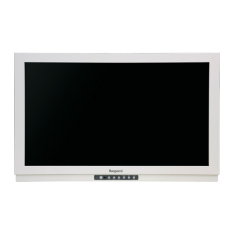
Ikegami MLW-2625C User manual

INSTRUCTION MANUAL
Full HD 26-inch Double-screen Multi-format LCD Color Monitor
Model MLW-2625C
Ikegami Tsushinki Co., Ltd.

Thank you for choosing this Ikegami HD Monitor. Please read this Instruction manual carefully to
keep your Ikegami products at peak performance for a longer service period. All Ikegami products are
designed and manufactured with utmost care and craftsmanship to provide long life and high quality
performance, if it is properly used and maintained as outlined in this manual.
This high performance LCD (Liquid Crystal Display Panel) monitor is equipped with the latest preci-
sion display panel of 26 inch diagonal size, which has an extremely accurate pixel arrangement for
sharp reproduction and a lot of useful facilities and functions in a rugged but light weight and easy-to-
use design to allow for a wide range of uses in many different applications for professional people.
This Ikegami product is made of ECO friendly components based upon the Company policy and corpo-
rate social responsibility to contribute towards the Global Environmental Solution for energy conser-
vation and environmental sustainability, all the components used in this product are Non-hazardous,
Toxic Free, Non-Lead and conform with Japan’s Green Product regulation, EU’s RoHS directive and
other Environmental and hazardous chemical substances related regulations and laws.

SA 1966SA 1965
CAUTION
RISK OF ELECTRIC SHOCK
DO NOT OPEN
CAUTION: TO REDUCE THE RISK OF ELECTRIC SHOCK, DO NOT REMOVE COVER
(OR BACK).
NO USER-SERVICEABLE PARTS INSIDE. REFER SERVICING TO
QUALIFIED SERVICE
PERSONNEL.
The lightning flash with arrowhead inside a triangle is intended to warn the user that
parts inside the product are dangerous and many cause electrical hazards.
The exclamation mark inside a triangle is intended to inform users that important
operating and servicing instructions are provided with the equipment.
SA 1966
SA 1965
WARNING: FOR CONTINUED SAFETY, REPLACE SAFETY CRITICAL COMPONENTS
ONLY WITH MANUFACTURE’S RECOMMENDED PARTS (REFER TO
SERVICE LITERATURE).
WARNING: TO REDUCE THE RISK OF ELECTRIC SHOCK, DO NOT EXPOSE
THIS EQUIPMENT TO RAIN OR WATER.
Instructions for Disposal of Electrical and Electronic Equipment in Private
Households
Disposal of used Electrical and Electronic Equipment
(
Applicable in the European Union and other European countries with garbage separate
disposal and collection methods
)
This symbol on the product, or in the related documents in the package, indicates that this
product shall not be treated as normal household waste. Instead, it should be taken to a proper applicable
collection point or depot for the recycling of electrical and electronic equipment.
By ensuring this product is disposed of correctly, you will help prevent possible negative consequences for
the environment and human health, which could otherwise be caused by inappropriate waste handling of
this product. The recycling of materials will help to conserve natural resources.
For more detailed information about recycling of this product, please contact your local city authority, your
household waste disposal service or the place where you purchased the product.
NOTE:
This equipment has been tested and found to comply with the limits for a Class A digital device,
pursuant to Part 15 of the FCC Rules. These limits are designed to provide reasonable protection
against harmful interference when the equipment is operated in a commercial environment. This
equipment generates, uses and can radiate radio frequency energy and, if not installed and used in
accordance with the instruction manual, may cause harmful interference to radio communications.
Operation of this equipment in a residential area is likely to cause harmful interference in which
case the user will be required to correct the interference at his own expense.
CAUTION;
ANY CHANGES OR MODIFICATIONS NOT EXPRESSLY APPROVED BY THE BODY
RESPONSIBLE FOR COMPLIANCE COULD VOID THE USERS AUTHORITY TO OPERATE
THE EQUIPMENT.

IMPORTANT SAFETY INSTRUCTIONS
1. General
1) Read all instructions provided.
2) Save these instructions for future use.
3) Follow all warnings and instructions marked on the monitor equipment.
4) Never insert objects of any kind into this monitor through cabinet slots as they may come in contact with
dangerous voltage points or short out parts, resulting in fire or electrical hazards, Never spill liquid of
any kind on the monitor.
5) Do not attempt to service this monitor yourself as operating or removing covers many expose you to a
dangerous voltage or other hazards, Refer all servicing to qualified service personnel.
6) Do not use attachments not recommended by the monitor equipment manufacturer as they may result
in the risk of fire, electric shock, or injury to persons.
7) This monitor has been pre-adjusted to meet the respective standard signals. So, it cannot be used with
the signals of different standards.
8) When keeping or transporting the unit for a long time, pack it in the supplied carton or equivalent.
2. Power supply
1) This monitor equipment should be operated only from the type of power source indicated on the marking
label.
2) This monitor equipment is provided with a three-wire grounding type plug with a third (grounding) pin.
This plug will only fit into a grounding-type power outlet. This is a safety feature. If you are unable to
insert the plug into the outlet, contact your electrician to replace either the plug or your obsolete outlet.
Do not defeat the safety purpose of the grounding-type plug.
3) When connecting and disconnecting the power cable, be sure to hold the plug.
4) Do not allow anything to rest on the power cord. Do not place this monitor equipment where the cord will
be abused by persons walking on it.
5) For added protection for this monitor equipment during a lightning storm, or when it is left unattended
and unused for long periods of time, unplug it from the wall outlet. This will prevent damage to the
equipment due to lightning and power -line surges.
6) Do not overload wall outlets and extension cords as this can result in fire or electric shock.
3. Usage and location
1) Do not use this Color LCD Display equipment near water - for example, near a bath tub, kitchen sink, or
laundry tub, in a wet basement, or near a swimming pool, or the like.
2) Do not place this Color LCD Display equipment on an unstable cart, stand, or table. The Color LCD
Display equipment may fall, causing serious injury to children and adults, and serious damage to the
equipment. Use only with a cart or stand recommended by the manufacture, or sold
with the Color LCD Display equipment. Wall or shelf mounting should follow the
manufacture’s instructions, and should use a mounting kit approved by the
manufacture. Color LCD Display equipment and cart combination should be moved
with care. Quick stops, excessive force, and uneven surfaces may cause the equipment
and cart combination to overturn.
3) Slots and openings in the cabinet and the back or bottom are provided for vitiation, and to ensure
reliable operation of the monitor and to protect it from overheating, these openings should never be
blocked or covered. The openings should never be blocked by placing the Color LCD Display equipment
on a bed, sofa, rug, or other similar surface. (This Color LCD Display equipment should never be placed
near or over a radiator or heat register.) This Color LCD Display equipment monitor should not
be placed in a built-in installation such as a bookcase unless proper ventilation is provided.
4) Avoid operating or placing (keeping) in a hot (+35ºC or over) or cold (less than +5ºC), high vibration, or
dusty place. Avoid operating or storing in a place exposed to direct sunlight.
5) If an image of extremely high brightness is displayed on the screen for a long time, the panel may get
burned in.

4. Cleaning
1) Unplug this Color LCD Display equipment from the wall outlet before cleaning. Do not use liquid cleaners
or aerosol cleaners. Use a damp cloth for cleaning.
2) Do not use thinners or petroleum products for cleaning. Otherwise, the cabinet may deform or the paint
may peel away .
5. Repair
1) Unplug this Color LCD Display monitor from the wall outlet and refer servicing to qualified service
personnel under the following conditions:
a. When the power cord or plug is damaged or frayed.
b. If liquid has been spilled into the Color LCD Display.
c. If the Color LCD Display monitor has been exposed to rain or water.
d. If the Color LCD Display does not operate normally by following the operating instructions. Adjust
only those controls that are covered by the operating instructions as improper adjustment of other
controls may result in damage and will often require extensive work by a qualified technician to
restore the Color LCD Display monitor to normal operation.
e. If the Color LCD Display monitor has been dropped or the cabinet has been damaged.
f. When the monitor exhibits a distinct change in performance - this indicates a need for service.
2) When replacement parts are required, be sure the service technician has used replacement parts specified
by the manufacture that have the same characteristics as the original parts.
Unauthorized substitutions may result in fire, electric shock, or injury to persons.
3) Upon completion of any service or repairs to this monitor, ask the service technician to perform routine
safety checks to determine that the Color LCD Display is in safe operating condition.
4)
For repair service, contact Ikegami’s authorized sales representative or Ikegami service desk directly.
IMPORTANT SAFETY INSTRUCTIONS
1) Never let this unit fall or subject it to strong shock.
2) Do not remove the cabinet unless necessary. High-voltage parts are contained in the cabinet and they
are very dangerous if you touch then. Only qualified service engineers are allowed to adjust the internal
parts of the cabinet.
3) This color monitor has been adjusted to signals conforming to each broadcasting standard. It cannot be
used for signals of different broadcasting standards. Be sure to operate the colour monitor within the
voltage range marked on its back.
4) If cabinet or screen is dirty, wipe with soft cloth. At this time, avoid using petroleum based products or
thinner, otherwise the paint may peel away.
5) Note that, if video signals with high luminance are monitored on the LCD panel over a long period of
time, the panel may burn in the image.
6) Avoid using or storing this unit in the following places:
• Hot (+35ºC or more) or cold (+5ºC or less) places, especially where this unit may be exposed to
the direct rays of the sun.
• Humid and dusty places.
• Places where there is considerable vibration.
• Places exposed to rain or water.
• When storing or transporting this unit, pack it in the supplied carton or equivalent.
7) If no image can be monitored even after performing user adjustment or the unit appears faulty, do not
dismantle this unit by yourself. In such cases, contact the Ikegami service desk.
8)
Should this unit fail within one year after delivery, it will be repaired free of charge unless the malfunction was
caused by mishandling or misuse of the user. However, the fuses are not covered by the warranty.
9) The specifications and appearance of this unit may be subject to change for further improvement without
prior notice.
OPERATING PRECAUTIONS

Contents
1. Precautions ............................................................................................................ 1-3
2. General Description .............................................................................................. 4-5
2.1 Features ........................................................................................................ 4
2.2 About Input Signals ...................................................................................... 4
2.3 Functions ....................................................................................................... 5
3. Names of Parts ...................................................................................................... 6
3.1 Names of Parts and Their Functions ........................................................... 6
4. Input Signal Connection ....................................................................................... 7
4.1 NTSC/PAL Analog Video .............................................................................. 7
4.2 NTSC/PAL Analog S-Video ........................................................................... 7
4.3 RGB or YPbPr Analog signals ...................................................................... 7
4.4 PC Analog signal ........................................................................................... 7
4.5 PC Digital signal ........................................................................................... 7
4.6 NTSC/PAL/HD Digital Video ....................................................................... 7
4.7 Remote Connection ....................................................................................... 7
5. Operation ............................................................................................................... 8-16
5.1 Key Operation ............................................................................................... 8
5.2 Display with a Signal Being Selected .......................................................... 8
5.3 Settings and Key Operation ......................................................................... 9
5.4 Status Screen ................................................................................................ 10
5.5 User Setting Screen ...................................................................................... 10-11
5.6 Display Setting Screen (main) ..................................................................... 12-13
5.7 Display Setting Screen (sub) ........................................................................ 13
5.8 Image Setting Screen ................................................................................... 14-15
5.9 Color Adjustment Screen .............................................................................. 15
5.10 Memory Select Screen .................................................................................. 16
5.11 Remote control .............................................................................................. 17
6. Applicable Signals................................................................................................. 18
6.1 Video Signals ................................................................................................. 18
6.2 D-SUB/DVI-D Computer Signals ................................................................. 18
7. Troubleshooting ..................................................................................................... 19-20
8. Specifications ........................................................................................................ 21-22
9. Use the stand ........................................................................................................ 23

1
1. Precautions
• When you open the cardboard box of the LCD monitor, please check that the
indicated accessories and cables are present.
It is recommended not to dispose of the packaging materials and to store them for
later use if it becomes necessary to transport again for after-sales service, or
maintenance purposes.
• Do not install this LCD monitor in a water-splashed or highly humid environment.
• Do not use the LCD monitor where the ambient temperature drops below +5°C or
Rises above +35°C. The images and component parts may be adversely affected or
the monitor may not function correctly.
• Do not open the case of the monitor body, unless it is absolutely necessary for setup
or installation because there are precision electrical and electronic components
inside and an accident may result.
• Do not put anything metallic or other foreign substances into the body, as a fire or
electric shock may result.
• Be sure to turn off the power before installing or making connections.
• Do not install the monitor in places exposed to heat, vibrations and shocks.
• Be careful not to drop or give a strong shock to this monitor while transporting it.
• It is not recommended to touch the surface of LCD panel.
• Please ensure that this device and other devices dose not produce improper operation
by the electromagnetic or other interference.
* Because of the digital image device characteristics, images may look unnatural at
high temperatures, this does not mean the monitor is faulty.

2
1. Precautions
Warning on power connection.
The United States
NEMA 5-15P
HOSPITAL GRADE
10A/125V
UL
Type SJT
Plug Type
Rated Voltage & Current
Safety Approval
Plug Configuration
Power Cord
Canada
NEMA 5-15P
HOSPITAL GRADE
10A/125V
CSA
Type SJT
Continental Europe
CEE7
EURO
10A/250V
VDE
H05VV-F
Use a proper power cord for your local power supply.
Requested from external connected equipment.
All the equipment connected to this unit shall be certified according to Standard
IEC60601-1 applicable to the equipment.
Symbols on the unit
Symbol Location This symbol Indicates
Front Standby SW
Main power switch.
Power Bottom : ON
: OFF
Front Brightness Control
Front Contrast Control
Bottom Potential Equalization Terminal

3
1. Precautions
Maintenance
• Clean the cabinet, panel and controls with a soft cloth lightly moistened with a mild
detergent solution. Do not use any type of abrasive pad, scouring powder or solvent, such
as benzene.
• Do not rub, touch, or tap the surface of the screen with sharp or abrasive items such as a
ball-point pen or screwdriver. This type of contact may result in a scratched picture panel.
• Clean the screen with a soft cloth, If you use a glass cleaning liquid. Do not use any type
of cleaner containing an anti static solution or similar additive as this may scratch the
screen’s coating.
About EN60601-1-2 (EMI)
This equipment has to install the following core.
• For DVI, PC Cable: Add Attached SFT-59SN to root part.

4
2. General Description
2.1 Features
●High-resolution image display
The full high-definition panel with the resolution of 1920(H) x 1200(V) dots is employed
to get very fine images displayed.
●Higher brightness and wider view angle
The view angle is as wide as 178°from all directions. No matter where the monitor is set
up, images can be comfortably viewed from different angles. Its brightness is also as high
as 400 cd/m2.
●Less afterimages
The LCD panel has a higher response speed, which reproduces images with less
afterimages.
●10-bit signal processing
Input signals are processed to 10-bit signals, enabling smoother gradation.
●Jaggy-less I/P conversion (Interlaced-to-Progressive conversion)
The unit is equipped with a jaggy-less I/P converter in order to convert NTSC, PAL and
HD interface signals to natural-looking images with unnoticeable jagged lines.
●Compatible with various types of signals
HDTV (1080i, 720P), SDTV (NTSC, PAL), PC inputs (analog and digital), SD-SDI and
HD-SDI signals can be applied.
●User-preset memory
The white balance, screen size, positioning and other factors can be registered in the
memory. Those factors are ready to select to make four different groups of settings to
your taste.
●Meeting many safety standards
The medical-use monitor conforms to US UL60601-1, Canadian CSA22.2 No. 601.1 (cUL)
and European EN60601-1 safety standards too.
●MLW-2625C is a monitor intended for use in a medical environment to display pictures
from cameras or other system.
2.2 About Input Signals
●NTSC/PAL inputs (BNC and S terminal inputs)
The unit handles NTSC and PAL composite video signals as well as Y/C signal in a multi-
format way. These signals are automatically identified to convert to images.
●RGB and component signal inputs (BNC)
Various types of signals - NTSC, PAL, 480P, 576P, 1080i and 720P, for instance - can be
readily handled for images.
●Analog RGB (HD-15) and DVI-D signal inputs
Computer signals - VGA, SVGA, XGA, SXGA, UXGA and WUXGA - can also be readily
accepted for images.
●Input of external sync signals
The unit can get in sync with external signals such as from cameras and sync signal
generators.
●SDI signals
The monitor is standard equipped with an SDI unit to get images from SD-SDI (NTSC,
PAL), HD-SDI (1080i, 720P) and other digital signals.

5
2.3 Functions
●Color temperature switching function
The color temperatures can be chosen from 6500K, 9300K and user settings to select a
color rendering to your taste.
●Gamma level switching function
The gamma level can be selected, compatible with DICOM14, from 1.8 to 2.6 (in 0.2
increments),
●Aspect ratio switching function
The display aspect ratio of video signals can be selected in the view angle size of 4 : 3 or
16 : 9.
●User setting memory switching function
Colors, brightness and other image quality-related settings are user-adjustable for four
different groups. They are readily switchable.
●Input signal selection function
Input signals can be selected from many types: composite, Y/C, RGB (component), analog
RGB (computer HD-15) and DVI-D (computer, video).
●Power management function
If no input signal is given for a preset time, the unit goes into a mode in which the power
consumption is automatically suppressed.
●Key lock function
The adjustment keys on the front can be locked to prevent wrong operation.
●External remote control function
An externally connected device may be used to select input signals and to make various
settings.
●Options
• Stand (TS-261)
The optional stand is available to place the monitor for desktop use.
• Multi SDI input unit
The optional unit is designed to add another line for the standard SDI input.
• RGB input unit
The optional unit is designed to add another line for the standard PC/DVI input.
2. General Description

6
3. Names of Parts
3.1 Names of Parts and Their Functions
Front
Back
Note: Various signal inputs (composite, Y/C and RGB) are
automatically terminated. With the main power off,
however, the S-Video signal terminates itself off even
when the output connector is not connected.
1 2 3 4 5 6 7 8
9
10
11
12
13
14
15
16
22 21 2023 19 18 17
①Power indicator
②Standby power switch
③Input 1
④Input 2
⑤MENU
⑥PIP SEL /-
⑦SWAP/+
⑧Contrast/
Brightness/
Exit
⑨SDI input
⑩SDI output
⑪Video input/output
⑫S-Video input/output
⑬Y/G input/output
⑭Pb/B input/output
⑮Pr/R input/output
⑯Sync input/output
⑰PC (RGB) 1 input
⑱DVI-D1 input
⑲Option input
(SDI or PC/DVI)
⑳COM (Service Port)
※Serviceman only
21
AC input
22
Power switch
23
Potential
Equalization
Terminal
This symbol
appears next to the
display’s Potential
Equalization
Terminal (ground
post)

7
4. Input Signal Connection
Connect the input signals in the following way.
4.1 NTSC/PAL Analog Video : Connected to the Video input.
4.2 NTSC/PAL Analog S-Video: : Connected to the S-Video input.
4.3 RGB or YPbPr Analog signals (BNC connector)
G/Y: Connected to Component G/Y input.
B/Pb: Connected to Component B/Pb input.
R/Pr: Connected to Component R/Pr input.
Sync: Connected to Component Sync input.
4.4 PC Analog signal : Connected to PC input. (15P D-SUB connector)
4.5 PC Digital signal : Connected to DVI input.
4.6 NTSC/PAL/HD Digital Video : Connected to SDI input.
Note: Various signal inputs (composite, Y/C and RGB) are automatically terminated. Be
sure to connect them to the input side because otherwise malfunction may occur.

8
5. Operation
5.1 Key Operation
There are seven front keys as shown below.
The keys have the following functions.
Standby SW : Used to turn on and off the power.
INPUT1 : Used to select the main input signal.
INPUT2 : Used to select the sub input signal.
MENU : Used to display the menu.
-/P.SEL : Used to select the setting menu, to make adjustments and to switch
between the main and sub PIP.
+/SWAP : Used to select the setting menu, to make adjustments and to switch
between the main and sub images.
CONT/BRT/EXIT : Used to put the contrast, brightness and other settings in memory
and to exit.
If no operation is made within the OSD User Time Out setting, the pre-adjusted settings
are resumed and the OSD disappears.
5.2 Display with a Signal Being Selected
5.2.1 Main and Sub Screen Display
INPUT1 : IN1 Input and Signal name
INPUT2 : IN2 Input and Signal name
With no signal being input
: INx and -
5.2.2 Input Display
SDI : SDI
COMPONENT : COMPONENT
PC : PC
DVI : DVI
VIDEO : VIDEO
S-VIDEO : S-VIDEO
5.2.3 Signal Name Display
SD Video line : 480i, 575i
HD Video line : 720/50P, 720/60P, 1080/50i, 1080/60i (59.94 Hz is expressed as 60 Hz.)
PC line : VGA, SVGA, XGA, SXGA, WUXGA
DVI line : VGA, SVGA, XGA, SXGA, WUXGA
With no signal being input
: No Signal
Power
Indicator
Standby SW INPUT1 INPUT2 MENU -/P.SEL +/SWAP CONT/BRT/EXIT

9
5.3 Settings and Key Operation
The setting function is for signals currently being inputted and selected.
Press the MENU key once, and the main-screen adjustments can be made. At the second
push, the sub-screen adjustments can be made.
5.3.1 Direct Brightness/Contrast Settings and Adjustments
1) Contrast
Press the “CONT/BRT” key, and the settings show up. The settings are adjusted with the
“+” or “-” key. Press the “CONT/BRT” key again to save the current settings and to exit
this mode.
2) Brightness
Press the “CONT/BRT” key, and the settings show up. The settings are adjusted with the
“INPUT1” or “INPUT2” key. Press the “CONT/BRT” key again to save the current settings
and to exit this mode.
5.3.2 Input Signal Selection
At the first key operation, the current input signal is accepted. By using the key within 5
seconds, the input signal is switched over. The INPUT1 and INPUT2 keys are used to
select the main screen and sub screen, respectively. The last input signal is picked up in
its shut-off state when the power is turned on again.
INPUT1: Used to select the main-screen input, INPUT2: Used to select the sub-screen
input.
The input being selected with INPUT1 cannot be selected with INPUT2. The Video and
S-Video signals, PC and COMP signals, as well as OP-PC and OP-DVI signals cannot all
be selected in pairs.
5.3.3 P.SEL
The double-screen display selector key is pressed to change the display in the order of
PINP1, PINP2, SBS1 and SBS2.
ýýýýýýýýýýý
5.3.4 SWAP
In the double-screen display mode, this key is used to switch between the main and sub
screens.
5.3.5 OSD Menu Operation
Press the MENU key, and the Status screen shown below appears. The tabs are selected
with the “+” or “-” key and fixed with the”MENU”key. The selected tabs change color. All
the new settings are saved by pressing the EXIT key once. Press the EXIT key again, and
the operation is completed. If no saving takes place, select UNDO, press MENU first and
then EXIT. The operation ends with the previous settings intact.
5. Operation
Main Main Sub Main Sub Main
Sub Sub
PINP1
Small sub-screen
display
PINP2
Large sub-screen
display
SBS1
Reduced full display
SBS2
Dot-by-dot display

10
5.4 Status Screen
This screen is used to display the current input signal information and the monitor settings.
Screen display
Status User Display Image Color Memory
IN1:CHname-Signalname
IN2:CHname-Signalname
○
SignalSet.Component
UserMemory
ColorMode
Gamma
OptionBoard
H/V.Frequency
RGB
RGB
RGB
RGB
RGB
User1
User
2.2
NoOption
**.*kHz/**.*H z
PC
DVI
OP-PC
OP-DVI
Switchbehaviordescription
Status setting screen description
The selected input signal and the setting status are displayed.
• Signal Set Component: Used to display the format setting of each input signal; RGB
or YPbPr.
• User Memory: Used to display the number of selected memory.
• Color Mode: Used to display the selected color setting.
• Gamma: Used to display the selected gamma level.
• Option Board: Used to display the added optional board.
• H/V. Frequency: Used to display the frequency of input video signal.
5.5 User Setting Screen
This screen is used to make the power save, backlight, OSD position and other settings.
Screen display
Status User Display Image Color Memory
IN1:CHname-Signalname
IN2:CHname-Signalname
○ Switchbehaviordescription
DPMS
BackLight
OSDPosition
OSDTimeOut
FrontKeyLock
Language
InputSkip
PinPPosition
PinPSelect
DVIEQ
OP-DVIEQ
UNDO
OFF/ON
0-255
1-5
OFF/10s/30s/60s
OFF/ON
None
OFF/ON
1-4
ALL/PinP1/PinP2/SBS1/SBS2
09/14/18/21/24/26/30dB
None
ON
255
1
30s
OFF
N/A
OFF
1
ALL
21dB
21dB
5. Operation

11
User Setting Screen
• DPMS: When set at ON, the display power management function puts
the unit in the power-save mode if a selected input has no
signal and no key is operated for longer than 30 seconds. The
backlight is automatically turned off.
Power OFF/ON: To be resumed by feeding a signal or operating
a key.
• BackLight: Used to change the backlight brightness of the LCD panel.
The adjustable range is from 0 to 255.
• OSD Position: Used to select the on-screen display position. The numerical
settings allow the following display positions.
1: Upper right, 2: Top center, 3: Upper left, 4: Lower right, 5:
Lower left
• OSD User Time Out: Used to set the time for the on-screen display to disappear.
The OSD disappears in any of the following time settings.
10s: 10 seconds, 30s: 30 seconds, 60s: 60 seconds, OFF: No
time setting
With this function, the OSD turns itself off if the OSD setting
key is not operated within a preset time.
• Front Key Lock: At the ON position, all the front keys are inoperative. No
operation is possible.
To unlock the front keys, hold down the “EXIT” key and turn
on the power. The unlock status is automatically saved.
• Input Skip: At the ON position, the non-signal input is skipped when the
input signal is selected with INPUT1 or INPUT2.
• PinP Position: Used to select the picture-in-picture display position. The
numerical settings allow the following display positions.
1: Upper left, 2: Upper right, 3: Lower left, 4: Lower right
• PinP Select: Used to select the picture-in-picture mode. There are four
modes to choose from: PinP1, PinP2, SBS1 and SBS2.
• DVI EQ/OP-DVI EQ: This cable compensation function helps suppress noises when
the DVI is connected using a long cable and suffers from noises.
The DVI EQ setting is to adjust the standard input, and the
OP-DVI EQ setting for an optional board.
5. Operation

12
5. Operation
5.6 Display Setting Screen (main)
This screen is used to make the input signal display aspect ratio, horizontal and vertical
display positions and sizes, and other settings.
Screen display
Status User Display Image Color Memory
IN1:CHname-Signalname
IN2:CHname-Signalname
○ Switchbehaviordescription
Aspect
OverScan
H.Position
V.Position
H.Size
V.Size
Clock
Phase
Auto
UNDO
Normal/Full/Clear
OFF/10%/20%
-200-+200
-200-+200
-200-+200
-200-+200
0-100
Auto/1-48
Cancel/ADJ
None
Normal
OFF
0
0
0
0
50
Auto
Cancel
Display setting screen description (main)
• Aspect: Used to switch the video signal aspect ratio from Normal, Full and
Clear. The switchable types depend on the type of input signal.
1600x1200display
Blackzoneson
bothsides
1920x1080display
Blackzonesattop
andbottom
HD
NTSC/PAL
Normal
1920x1200display
Cutoffattop
andbottom
1920x1200display
Cutoffonbothsides
Full
640x480display
1920x1080display
Clear
• Over Scan: Used to select the display size with an overscan of 10% or 20%.
• H/V. Position: Used to adjust the horizontal and vertical positions onscreen.
Move toward the plus side to shift the screen to top right.
Move toward the minus side to shift the screen to bottom left.
• H/V. Size: Used to adjust the horizontal and vertical sizes onscreen.
Move toward the plus side to enlarge the display size.
Move toward the minus side to reduce the display size.
• CLOCK: Used to adjust the number of sampled dots with VIDEO/S-VIDEO
and DVI analog signals.
Increase the setting to get the sampling frequency higher. Decrease
it to get the sampling frequency lower.
Make this adjustment if vertical stripes or noises occur.

13
• PHASE: Used to adjust the sampling point for VIDEO/S-VIDEO and DVI input
signals.
Make this adjustment if the rising edge of characters and the like
look blurry or fine patterns suffer from noises.
• AUTO: Used to make for automatic adjustment of the number of sampled
dots and the sampling point for analog signals other than VIDEO/S-
VIDEO and DVI signals.
5.7 Display Setting Screen (sub)
This screen is used to make the input signal display aspect ratio, horizontal and vertical
display positions and sizes and other settings.
Screen display
Status User Display Image Color Memory
○ Switchbehaviordescription
OverScan
H.Position
V.Position
Clock
Phase
Auto
UNDO
OFF/10%/20%
-200-+200
-200-+200
0-100
Auto/1-48
Cancel/ADJ
None
OFF
0
0
50
Auto
Cancel
IN1:CHname-Signalname
IN2:CHname-Signalname
Display setting screen description (sub)
• Over Scan: Used to select the display size with an overscan of 10% or 20%.
• H/V. Position: Used to adjust the horizontal and vertical positions onscreen.
Move toward the plus side to shift the screen to top right.
Move toward the minus side to shift the screen to bottom left.
• H/V. Size: Used to adjust the horizontal and vertical sizes onscreen.
Move toward the plus side to enlarge the screen.
Move toward the minus side to reduce the screen.
• CLOCK: Used to adjust the number of sampled dots with analog signals other
than VIDEO/S-VIDEO and DVI signals.
Increase the setting to get the sampling frequency higher. Decrease
it to get the sampling frequency lower.
Make this adjustment if vertical stripes or noises occur.
• PHASE: Used to adjust the sampling point for input signals other than VIDEO/
S-VIDEO and DVI signals.
Make this adjustment if the rising edge of characters and the like
look blurry or if fine patterns suffer from noises.
• AUTO: Used to make for automatic adjustment of the number of sampled
dots and the sampling point for analog signals other than VIDEO/S-
VIDEO and DVI signals.
5. Operation

14
5. Operation
5.8 Image Setting Screen
This screen is used to adjust the contrast, brightness and other video signal-related display
conditions.
Screen display
Status User Display Image Color Memory
○ Switchbehaviordescription
Contrast
Brightness
Sharpness
NoiseReduction
Smooth
Hue
Chroma
BlueOnly
VideoSetup
VideoFilterSelect
IPMode
UNDO
0-100
0-100
0-63
OFF/Weak/Middle/Strong
-63-63
0-8
OFF/ON
0/Mid/Hi
3D/Comb/Trap
Still/Motion
None
50
50
0
OFF
OFF
0
8
OFF
0
3D
Still
IN1:CHname-Signalname
IN2:CHname-Signalname
Image setting screen description
• Contrast: Used to adjust the signal’s white level gain.
Increase the setting to get images brighter, and decrease it to get
them darker.
• Brightness: Used to adjust the signal’s black level gain.
Increase the setting to get the black level higher, and decrease it
to get it lower.
• Sharpness: Used to adjust the sharpness.
Increase the setting to get images shaper, and decrease it to get
them softer.
• Noise Reduction: Used to reduce noises.
• Smooth: Used to make images smoother.
• Hue: Used to adjust the hue.
• Chroma: Used to adjust the color density.
Increase the setting to get the colors stronger, and decrease it to
get them weaker.
• Blue Only: Set it to ON, and the blue color only appears.
Feed the color bar signal and use this function, and the chroma
and hue adjustments can be easily made.
This function works with the NTSC system only.
• Video Setup: Used to select the setup level of composite and Y/C signals.
0: Offset set at 0%.
Mid: Offset set at 3%.
Hi: Offset set at 7.5%.
• Filter Select: Used to select a decoder filter.
This function works with the NTSC system only.
3D: Two-dimensional filter, Comb: Comb filter, Trap: Trap
The standard setting is 3D.
Table of contents
Other Ikegami Monitor manuals

Ikegami
Ikegami HLM-1705WR User manual

Ikegami
Ikegami HTM-1517R User manual

Ikegami
Ikegami C/T-20D User manual

Ikegami
Ikegami PM-580 User manual

Ikegami
Ikegami T-17A User manual

Ikegami
Ikegami PM-9050 User manual

Ikegami
Ikegami LCM-205N User manual

Ikegami
Ikegami TM20-20RH User manual

Ikegami
Ikegami LCM-971 User manual

Ikegami
Ikegami LCM-151 User manual

Ikegami
Ikegami HLM-2200 User manual

Ikegami
Ikegami C/T-20A User manual

Ikegami
Ikegami MLW-2425C User manual

Ikegami
Ikegami PM9-5A User manual

Ikegami
Ikegami HQLM-1720WR User manual

Ikegami
Ikegami MLW-1712C User manual

Ikegami
Ikegami PTM-4202 User manual

Ikegami
Ikegami HMM-1850 User manual

Ikegami
Ikegami TM14-80RH User manual

Ikegami
Ikegami HTM-1990R M User manual