iLC CME Series User manual
USER MANUAL
ILC Srl
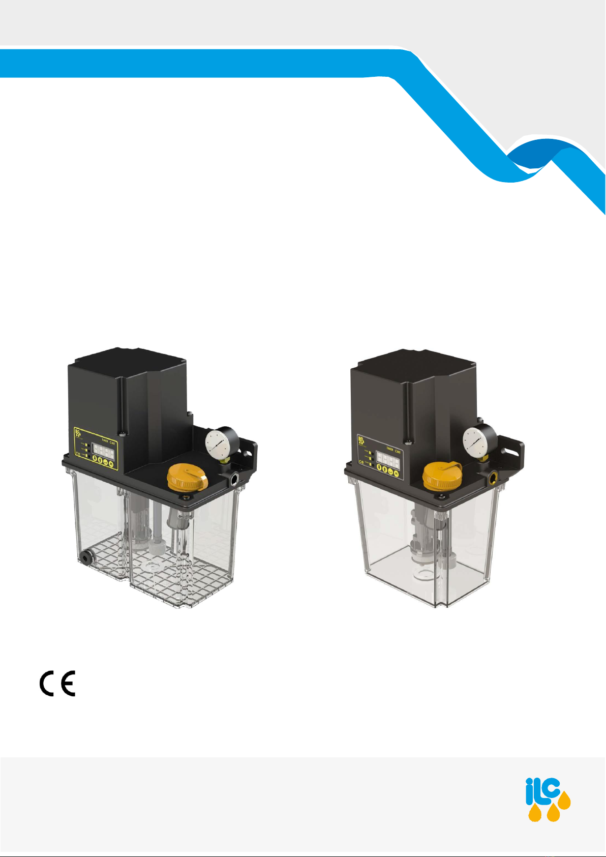
CME
CME series electric gear pump for oil and soft grease
Use in single-line and air+ oil centralised lubrication systems
Translationoforiginalinstructions
All ILC products must only be used for their intended purposes, as specified in this brochure and in all instructions. If the product is supplied together with user instructions, the user is required to read
them and comply with them. Not all lubricants are suitable for centralised lubrication systems. ILC lubrication systems or relative components cannot be used together with gas, liquid gas, pressurised
gasinsolution and liquids with vapour pressure exceeding normal atmospheric pressure (1013bar) by more than 0.5 bar, maximum temperature permitted. Any type of dangerous materials, inparticular
those classified as such by European Community Directive (EC) 67/548/EEC, Article 2 (2), can only be used in ILC centralised lubrication systems or relative components upon consultation with ILC and
after having received written approval from the company.
Copyright©2018 by I.L.C. Srl
All rights reserved.
I.L.C. srl - Via Garibaldi, 149 - 20155 Gorla Minore - Italy

TABLE OF CONTENTS
1.
Introduction 3
2.
Application 3
3.
Operating principle 3
4.
Technical specifications 3
5.
Installation 4
6.
Commissioning 4
7.
Hydraulic diagram 5
8.
Version without electronic board 6
Electrical connections 6
9.
Version with electronic board 7
10.
Operating mode 10
10.1
Operating Mode 10
10.2
Programming Mode 10
11.
Menu type selection 10
11.1
Setting Reduced Menu 10
11.2
Setting Complete Menu 10
12.
Pause and operating Mode setting 11
12.1
Program Pause time in h/m/s (FU-PL) 11
12.2
Program Pause time in pulses (FU-IL)
13.
Advanced programming (complete menu) 11
13.1
Set warm-up cycles operating Seconds* 11
13.2
Set warm-up cycles pause seconds* 11
13.3
Set warmupcycles number* 12
13.5 Pre-lubrication enabling 12
13.7 Pressure switch alarm enabling 12
13.4 Warm-up enabling* 12
13.6 Level alarm enabling 12
13.8 Air pressure switch alarm enabling** 12
14.
Maintenance 13
14.1
Maintenance table 13
15.
Transport 14
15.1
Delivery 14
15.2
Storage 14
16.
Operation 15
16.1
General information 15
16.2
Commissioning 15
17.
Decommissioning 16
17.1
Temporary decommissioning 16
17.2
Definitive decommissioning 16
17.3
Disposal 16
18.
Precautions for use 17
18.1
It is recommended to 17
18.2
Flammability 17
18.3
Pressure 17
18.4
Noise 17
19.
User instructions 18
19.1
Lists used 18
19.2
Inadmissible fluids 18
20.
Dimensions CME 2L 19
21.
Dimensions CME 3L 20
22.
CME order code configurator 21
23.
Fittings order codes 21
24.
Spare parts 22
25.
Warranty 23
26.
Machine identification 23
2

CME
Introduction
I.L.C. srl
- Via Garibaldi, 149 - 20155 Gorla Minore - Italy
Phone +39 0331 601697 - Fax +39 0331 602001 - www.ilclube.com -
info@ilclube.it
3
1.
Introduction
This use and maintenance manual refers to the CME pump.
Using this pump makes it possible to distribute oil or soft
grease in lubrication systems.
The latest version can be obtained by contacting the Sales
Technical Office.
The pump that this manual refers to must be used by qualified
personnel with basic hydraulic and electrical knowledge.
This use and maintenance manual contains important
information to protect the health and safety of personnel
who intend to use this equipment. This manual must be read
carefully and kept in good conditions so that it is always
available tooperatorswho intend to refertoit.
2.
Application
At this point the pressurised lubricant will activate a release
valve, which will discharge the pressure inside the tank and
enablethevolumetricvalvestobefilled.
The process repeats each time the motor is switchedon and
off.
When the system is at rest, a check valve maintains the main
line at a pressure of 0.5/0.6 bar, thus preventing air from
entering.
Thestatuschangeofthepressureswitchduringoperatingtime
allows us to ensure there are no oil leaks in the main line.
The lack of lubricant inside the tank is signalled by a minimum
level sensor.
4. Technical specifications
The CME gear pump has been designed for use in single-line
or air + oil centralised lubrication systems. These systems use
the principle ofpressure and release pulses andthe lubricant is
sent to the volumetric valves or to the mixers positioned near
thepoints of the machine to be lubricated.
Any use other than described above shall not be in agreement
with the specifications of I.L.C. srl (pump manufacturer), who
Measured capacities (A)
Electrical connections
100 cc/1' 50 Hz AC
120 cc/1' 60 Hz AC
200 cc/1' 24 V DC
1 cable gland for power supply
1 cable gland for signals
shall not be held responsible for any damage resulting from a
different use.
3. Operating principle
The pump sends pressurised lubricant through two side
outlets. This way the customer can connect the main pipe to
bothoutletsorto oneonly,pluggingtheunusedone.
When the motor is powered on, by an internal timer or an
externalPLC,thegearpumpisactivated, whichsends lubricant
from the reservoir to the distribution network through the two
outlets or through the selected one.
Pressurisation of the distribution network forces the volumetric
valves, whose metering chamber has been filled since the last
lubricationcycle,tosendthevolumeoflubricantinsidethemto
the points. Onceall thevalves have beenactuated, the pressure
will increase until a pressure switch is triggered and, after a
short time, it will be possible to interrupt motor operation.
Pressuregauge 0 - 60 bar
Oils from 20 to 1000 mm²/s
Soft greases NLGI 000 and 00
Protection rating
IP-65
Manual button amperage
1 A 250 V AC - 3 A 120 V AC
Noiselevel
<70db(A)
Operating mode S3, 20%
Max Operating Time
20% min×0.2 = 4 min. Pump cycle
with subsequent down time of 16
min.
Operating humidity
90% max
Storage temperature
10°C ÷ +40°C
Weight (empty tank)
3.5 Kg (2l)
4.3 Kg (3l)
Operating temperature
0°C - 50°C
Operating pressure
from 22 to 30 Bar
Tank capacity
2L - 3L
Outlet connections
2BSP1/4”seats (standardsupplied
with 1 left-hand lock cap)
Filling
Cap with 200 µ load filter
Lubricants

I.L.C. srl
- Via Garibaldi, 149 - 20155 Gorla Minore - Italy
Phone +39 0331 601697 - Fax +39 0331 602001 - www.ilclube.com -
info@ilclube.it
4
CME
Installation
5.
Installation
Onlyinstallthepumpinahorizontalposition,fasteningitto the
wall by two M6 bolts.
Anareaofferinga view ofthefrontpanel,easyaccessincase
of maintenance, easy access to the filling system and easy
connection to the distribution network is recommended.
Arrange space below the unit for any tank disassembly.
The unit allows connection to the distribution network from two
outlet ports and is supplied with a ¼” Gas cap installed on the
left side. In caseof supply from the left side, the cap must be
movedtotherightside.Ifthedistributionnetworkispresenton
both sides, the cap must be removed. The two outlets are both
¼" Gas and the 6 mm pipe fitting must be ordered separately
(codes below).
03-257-2 03-257-4
network, without creating pipe sections that go up and down.
This is in case air enters the distribution lines. Air bubbles
tend to rise towards the end of the distribution line and are not
removed along the way. The presence of air bubbles along the
distribution line prevents the correct operation of the metering
valves and mixers.
Use the pressure switch to check for leaks in the main line
during the lubrication cycles. For systems with a main line
exceeding 8 m, we recommend installing a pressure switch at
the end ofthe main line and not connecting the one onthe unit.
Caution!
All electrical connections must be set up by
qualified personnel and all requirements of
local regulations must be followed. Refer to
the electrical connection diagram for correct
wiring.
Caution!
The unit must be protected by a differential
magnetothermal switch with a breaking
threshold of 0.03 A and a max time of 1
second (breaking power = 10 KV
–
rated
current = 4A).
6.
Commissioning
The tank is filled with clean lubricant, without exceeding the
MAX level, by means ofthe load cap complete with filter (incase
of oil). It must be recommended by the machine manufacturer
and must comply with the following viscosities
ZZZ106-105-L ZZZ106-005-L
The unit is supplied with two cable glands, one for voltage and
the other for the controls.
All rigid pipes, flexible hoses and fittings must be compatible
with the lubricant, the operating pressure and the surrounding
environment. In general, try to install the unit in the lowest
position (vertically) in relation to the rest of the distribution
Loosen the cap in the distribution network furthest from the
unit. Supply the pump until lubricant leaks, air-free, from the
loose cap. Tighten the cap, run lubrication cycles until the
lubricant comes out ofthe volumetric valves. Fill the secondary
pipes with additional cycles. The system is now ready to
lubricate all points.
Oils from 20 to 1500 cSt
Soft greases
NLGI 000 or 00

I.L.C. srl
- Via Garibaldi, 149 - 20155 Gorla Minore - Italy
Phone +39 0331 601697 - Fax +39 0331 602001 - www.ilclube.com -
info@ilclube.it
5
CME
Hydraulicdiagram
7.
Hydraulic diagram
1 gear pump 6
pressure switch for controlling the main line
2 pressure relief valve 7
pressure gauge
3 release valve 8
intake valve
4 minimum level of lubricant check 9
electric motor
5
lubricant loading filter
P
7 6
MA DS
E
3
M
4
WS
ST
5
1
DBV
2
R
8
I.L.C. srl
- Via Garibaldi, 149 - 20155 Gorla Minore - Italy
Phone +39 0331 601697 - Fax +39 0331 602001 - www.ilclube.com -
info@ilclube.it
6
CME
Version withoutboard
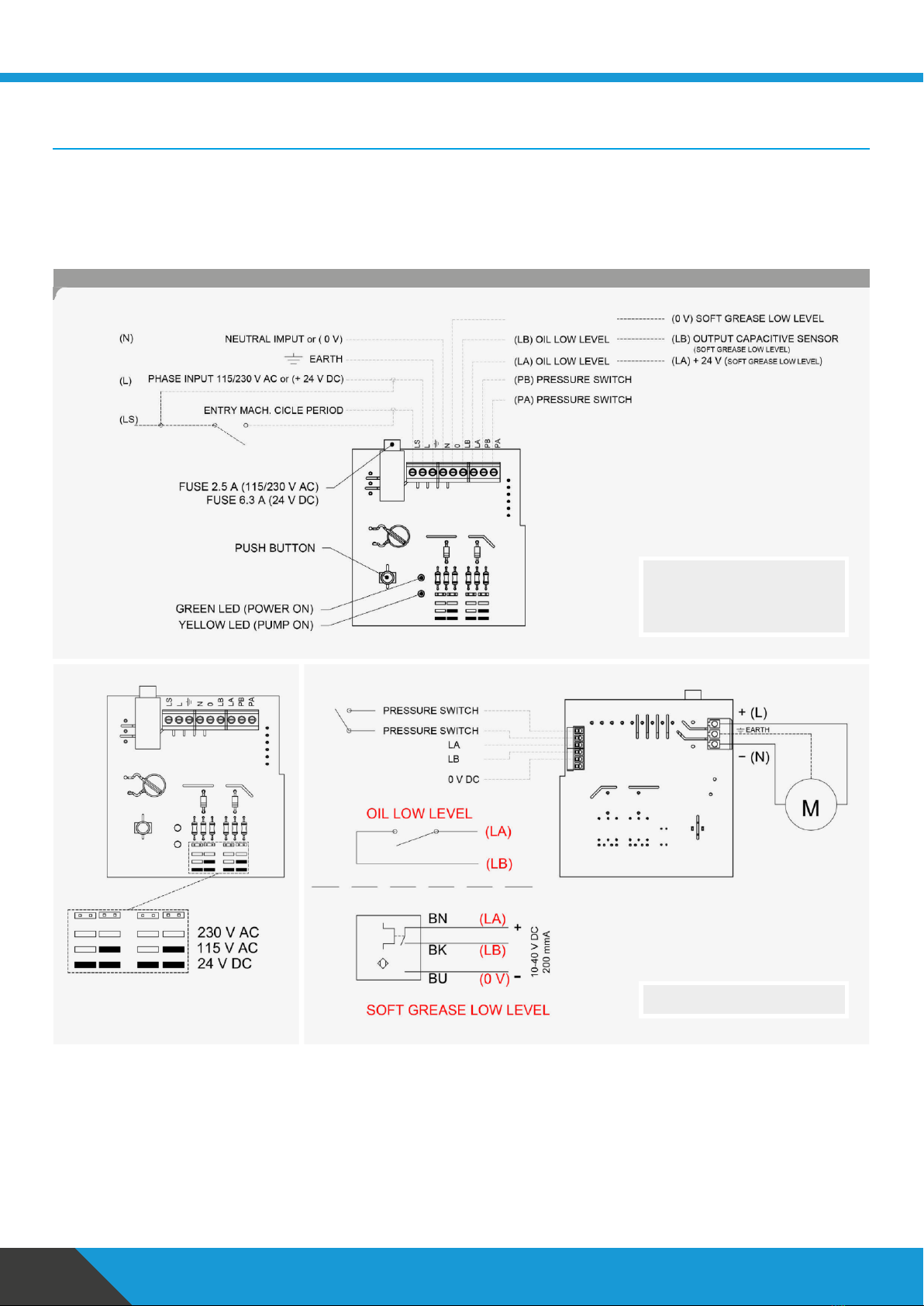
8.
Version without electronic board
The lubrication cycles are programmed by an external PLC. The pump is equipped with a board in which all electrical connections
merge and isequipped with a manual button for extra-cycles. Furthermore it will be possible to connect the contact ofthe minimum
lubricant level and the pressure switch to the PLC to generate any alarms.
Electrical connections
pause = the stop period of the pump / operation = the running time of the pump
For volumetric or air + oil systems with
pause and operation adjustable in
hours, minutes orseconds or pulse-
adjustable pause.
Connections set up by ILC.

I.L.C. srl
- Via Garibaldi, 149 - 20155 Gorla Minore - Italy
Phone +39 0331 601697 - Fax +39 0331 602001 - www.ilclube.com -
info@ilclube.it
7
CME
Version withboard
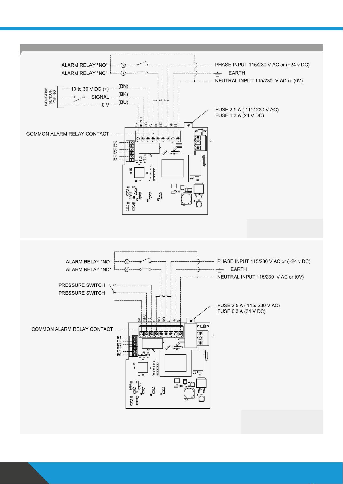
9.
Version with electronic board
Anelectronicboardisinstalledinsidethepumpwhichcontrolsandchecksthe operation oftheentiresystem.Theboardisequipped
with a display with 4 digits and 4 programming buttons, including the extra-cycle button. In this version, the pump isdelivered with
level alarm activated (AL-1), oil pressure switch alarm activated (AO-1) and prelube on (the pump starts when it is switched on and
operates for the set operating time) PL-1.
The pump can be programmed to:
•
immediately run a lubrication cycle when the motor is switched on (which we will call PRELUBE) or not.
•
Set a pause time (the pump stops) and an operating time (the pump operates)
•
Alternatively the pause (pump stopped) can be established innumber of pulses insteadof inhours/minutes/seconds. Once
the set number ofpulses is reached, the pump starts running for the selected operating time.
•
Settheminimumelectricallevelcontrolfunctionofthelubricant.
•
Set the oil pressure switch control function to check system operation.
•
Set the air pressure switch control function in the air + oil systems to check that air is always present in the system.
•
Adjustthewarm-updepending oncustomerneeds.
pause = the stop period of the pump / operation = the running time of the pump
Electrical connections
Forvolumetricorair + oil systems
with pause and operation adjustable
inhours,minutes orseconds.

I.L.C. srl
- Via Garibaldi, 149 - 20155 Gorla Minore - Italy
Phone +39 0331 601697 - Fax +39 0331 602001 - www.ilclube.com -
info@ilclube.it
8
CME
Version withboard
pause = the stop period of the pump / operation = the running time of the pump
For volumetric or air + oil systems.
for pulse pause time counted by a switch.
Electrical connections (continued)
Connections set up by ILC.
I.L.C. srl
- Via Garibaldi, 149 - 20155 Gorla Minore - Italy
Phone +39 0331 601697 - Fax +39 0331 602001 - www.ilclube.com -
info@ilclube.it
9
CME
Version withboard
pause = the stop period of the pump / operation = the running time of the pump
for air oil systems with air control through
a pressure switch. By checking the air
pressure switch, the pause cannot be
adjusted in pulses.
AIR
Electrical connections (continued)
For volumetric or air + oil systems.
For pulse pause time counted by a
proximity sensor.

CME
Modes andprogramming
I.L.C. srl
- Via Garibaldi, 149 - 20155 Gorla Minore - Italy
Phone +39 0331 601697 - Fax +39 0331 602001 - www.ilclube.com -
info@ilclube.it
10
10.
Operating mode
10.1 Operating Mode
In operating mode, the board controls the pump by
alternating work cycles with pause cycles. The duration
of the work stage can be configured as time while
the duration of the pause can be counted in time (PL
mode) or in number of pulses, which the board reads
via the dedicated input (IL mode).
Circularly scrolls the menus downwards
Enters programming mode if pressed for 3+ seconds
10.2 Programming Mode
Programming mode is accessed by holding the ENT
key for 3s. This mode allows the user to access and
change all the setting parameters of the board and
alarms.
Caution! In order to memorise the programming of
all entered changes, hold the Enter key for at least 5
seconds
after the changes have been made.
Then, the pump will automatically start for one cycle.
Circularly scrolls the parameters downwards
Increases the value of a parameter
If held for 5+ seconds, saves changes and switches to Operating mode
11.
Menu typeselection
Hold the
key down for 3 seconds to start
programming
ThewordE-CMappearswiththe3LEDs
flashing on the left.
Press the button
Select CM-b using
Press
E-CMappears.E-CM isnow in Reduced
Menu mode.
Hold the
key down for 3 seconds to
start programming
ThewordE-CMappearswiththe3LEDs
flashing on the left.
Press the button
Select CM-F using
Press
.
E-CMappears. E--CMisnowinComplete
Menu mode.
Circularly scrolls the parameters upwards
Decreases the value of a parameter
Circularly scrolls the menus upwards
11.1 Setting Reduced Menu
11.2 Setting Complete Menu
Key
Function
Accesses the parameter edit / validates a setparameter and goes back
to the overall parameter list.
Key
Function
Immediately starts an extra work cycle for the set time
Resets all alarms
CME
Pause/Operatingprogramming
I.L.C. srl
- Via Garibaldi, 149 - 20155 Gorla Minore - Italy
Phone +39 0331 601697 - Fax +39 0331 602001 - www.ilclube.com -
info@ilclube.it
11
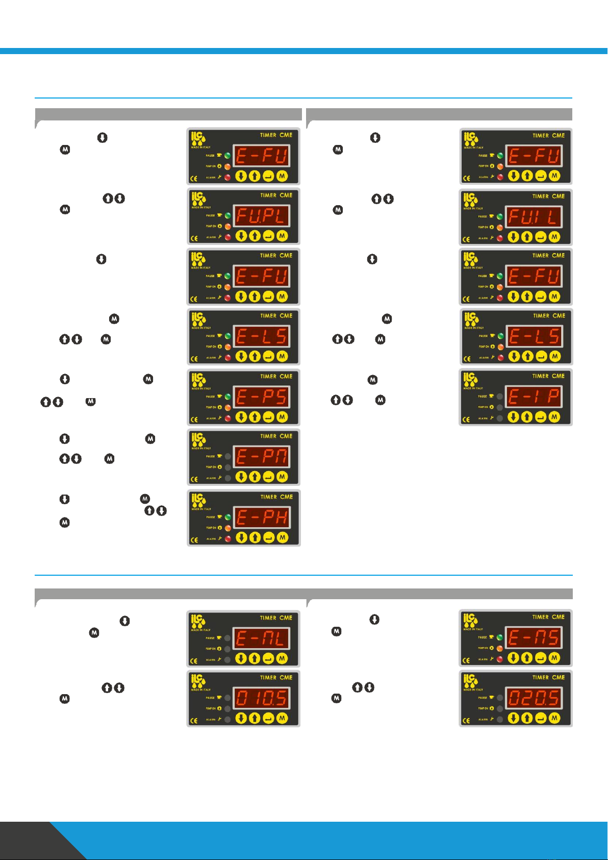
12.
Pause and operating Mode setting** (complete and reduced menu)
From E-CM Press .E-FUappears
Press
.
Select FU.PL using .
Press
to confirm and return to E-FU.
From EC-M Press
E-FU appears.
Press
.
Select FU.IL using .
Press
to confirm and return to E-FU.
From E-FU, press
From E-FU, press
E-LS appears. Press . Adjust the
operating time in seconds from 1 to a 60
using
Press
to confirm.
E-LS appears. Press . Adjust the
operating time in seconds from 1 to a 60
using
Press
to confirm.
Press
. E-PS appears. Press . Set a
pause time from 150 to 999
¹
seconds using
.Press
to confirm.
Press
. E-PM appears. Press .
Set a pause time from 0 to 999 minutes
using .Press
to confirm.
Press
. E-PH appears. Press . Set
atimefrom0to999hoursusing
.
Press
to confirm.
Select E-IP. Press .
Set the pause in pulses from 1 to 9999
using .Press
to confirm.
13.
Advanced programming (complete menu)
13.1 Set warm-up cycles operating Seconds* 13.2 Set warm-up cycles pause seconds*
From E-PH or E-IL, press . E-ML
appears. Press
From E-ML, press
.E-MSappears.
Press
Set the operating seconds for warm-up
cycles(1-60) using .
Press
to confirm.
Set the pause seconds for warm-up cycles
(1-60)using .
Press
to confirm.
¹ With E-PM=0 and E-PH=0 E-PS can only be adjusted from 150 to 999.
With E-PM or E-PH are different from 0 E-PS can only be adjusted from 0 to 999.
*functions only for air+oil systems exclusively for use by ILC
** pause = the stop period of the pump / operation = the running time of the pump
12.1 Program Pause time in h/m/s (FU-PL)
12.2 Program Pause time in pulses (FU-IL)
I.L.C. srl
- Via Garibaldi, 149 - 20155 Gorla Minore - Italy
Phone +39 0331 601697 - Fax +39 0331 602001 - www.ilclube.com -
info@ilclube.it
12
CME
Advanced programming
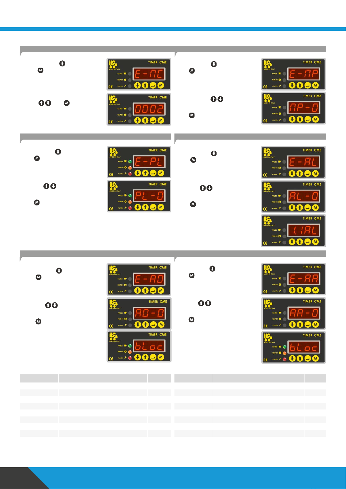
13.3 Set warmup cycles number* 13.4 Warm-up enabling*
From E-MS, press . E-MC appears.
Press
.
Set the warm-up cycles number (1-99)
using .Press
to confirm.
From E-MC, press
.E-MPappears.
Press
.
Select mode with
MP-0 indicates Warm-up not enabled.
MP-1 indicates Warm-up enabled.
Press
to confirm.
13.5 Pre-lubrication enabling
From E-MP, press
.E-PLappears.
Press
.
13.6 Level alarm enabling
From E-PL, press . E-AL appears.
Press
.
Select with
PL-0 prelube not enabled
PL-1 prelube enabled
Press
to confirm.
Select with
AL-0 alarm not enabled
AL-1 alarm enabled
Press
to confirm.
Inthe event ofanalarm, the display will
show 1.1AL. This alarm does not block the
pump if triggered.
13.7 Pressure switch alarm enabling 13.8 Air pressure switch alarm enabling**
From E-AL, press . E-AO appears.
Press
.
From E-AO, press . E-AA appears.
Press
.
Select with
AO-0 alarm disabled
AO-1 alarm enabled
Press
to confirm.
Select with
AA-0 alarm not enabled
AA-1 alarm enabled
Press
to confirm.
In the event of an alarm, the display will
show bloc.
This alarm blocksthepump iftriggered.
In the event of an alarm, the display will
showbloc.
This alarm blocks the pump if triggered.
Parameter
Description
Default
Parameter
Description
Default
E-CM
Menu type
b
MS
Warmup pause seconds
20
FU
Operating Mode
PL
MC
Warmup cycles
2
LS
Operating seconds
5
MP
Warm-up enabling
0
PS
Pause seconds
150
PL
Prelube enabling
0
PM
Pause minutes
0
AL
Level alarm enabling
1
PH
Pause hours
0
AO
Oil alarm enabling
1
IP
Pause pulses
2
AA
Air alarm enabling
0
ML
Warmup operating seconds
10
*functions only for air+oil systems exclusively for use by ILC
**to be enabled only if a pressure switch to control the air is required

I.L.C. srl
- Via Garibaldi, 149 - 20155 Gorla Minore - Italy
Phone +39 0331 601697 - Fax +39 0331 602001 - www.ilclube.com -
info@ilclube.it
13
CME
Maintenance
14.
Maintenance
Premature wear of pump gears and other moving parts is caused by contaminated and dirty lubricants.
Failure of the volumetric valves which, as a consequence, do not send lubricant to the points, is caused by the presence of air in the
distribution network or by contaminated lubricant. The unit does not require special maintenance if you avoid using contaminated
lubricant and injecting air into the hydraulic circuit. Before performing any operation, make sure you have disconnected the power
supply.
The maintenance table shows the main faults, causes and solutions. If the problem cannot be solved after consulting it, contact
the technical office at ILC.
14.1 Maintenance table
Symptoms
Potential causes
Potential solutions
1. The pump does not dispense
lubricant
1.1
Internal fittings loose or damaged
1.2
Gear pumpworn
1.3
Release or intake valve dirty or dam-
aged
1.1
Tighten the fittings
1.2
Replace the pump
1.3
Clean the valves
2. The pump does not dispense
lubricant at the operating
temperature
2.1
Pump worn
2.2
The pressure relief valve is not
calibrated correctly or is dirty and the
lubricant returns to the tank
2.3
Release valve dirty ordamaged
2.1
Replace pump
2.2
Replace the pressure relief valve
2.3
Replace the releasevalve
3. The release valve does not
open at the end of the
operating cycle and themain
line remainspressurised
3.1 Release valve dirtyor damaged 3.1 Replace the releasevalve
4. The main line is emptied during
the pause time
4.1
Loose fittings at pump outlet or along
the distribution line
4.2
check valve dirty ordamaged
4.3
Release valve dirty ordamaged
4.1
Tighten the loose fittings
4.2
Replace the check valve
4.3
Replace the releasevalve
5. The lubrication cycle is not
performed
5.1
Main line damaged or loose fittings
5.2
Uncalibrated pressureswitch
5.3
The pump does not dispense oil
5.4
The pump does notdispense lubricant
at the operating temperature
5.1
Repair the main line or tightenthe
fittings
5.2
Replace the pressure switch
5.3
See point 1.
5.4
See point 2.

I.L.C. srl
- Via Garibaldi, 149 - 20155 Gorla Minore - Italy
Phone +39 0331 601697 - Fax +39 0331 602001 - www.ilclube.com -
info@ilclube.it
14
CME
Transport
15.
Transport
TheproductsofI.L.C. Srlarepackagedto marketstandardaccordingtotheregulationsinforce inthecountryofdestination.Proceed
with caution during transport. The product must be protected against impact. There are no restrictions for transportation by land,
air or sea.
Caution!
Do not spill or throw away the product
15.1 Delivery
After receiving the shipment it is necessary to check the integrity of the products based on the accompanying documents. Packaging
materials must be kept until any discrepancies have been clarified.
15.2 Storage
The following storage conditions apply for I.L.C. Srl products:
Storageoflubricationunits
•
Environmental conditions: dry and dust-free environment, storage in a well-ventilated and dry location
•
Storage period: max. 24months
•
Admissible air humidity:<65%
•
Storage temperature: from 10° C to 40°C
•
Light: avoid direct exposure to sunlight or UV rays, isolate heat sources located in the vicinity
Storage of electronic and electrical equipment
•
Environmental conditions: dry and dust-free environment, storage in a well-ventilated and dry location
•
Storage period: max. 24months
•
Admissible air humidity:<65%
•
Storage temperature: from 10° C to 40°C
•
Light: avoid direct exposure to sunlight or UV rays, isolate heat sources located in the vicinity
General notes forstorage
•
Dust-protected storage by covering the devices with plastic film is recommended
•
Protection against floor humidity, by storing on shelves or on wooden structures
•
Before storage, it is recommended to protect the polished metal surfaces, specifically the friction components and the
assembly surfaces, by treating them with a long-term anticorrosion product
•
Approx. every 6 months: check for corrosion. If signs of corrosion are visible, it is recommended to eliminate them
immediately and treat again with the anticorrosive agent
•
The drives must be protected against mechanical damage

I.L.C. srl
- Via Garibaldi, 149 - 20155 Gorla Minore - Italy
Phone +39 0331 601697 - Fax +39 0331 602001 - www.ilclube.com -
info@ilclube.it
15
CME
Operation
16.
Operation
16.1 General information
The pump operates automatically. However, the flow of the lubricant inside the piping must be checked periodically.
The filling level of lubricant in the reservoir, being installed, must be visually checked periodically. If an excessively low lubricant level
isdetected, itmustbe toppedupto the maximum marking asdescribedinthe"Commissioning"chapter.
The information provided by the manufacturer of the machinery and of the lubricants must be strictly complied with.
Caution!
Only fill clean lubricant using a suitable device. The use of contaminated lubricants may cause very severe system
malfunctions. The lubricant reservoir must be filled avoiding the formation of bubbles.
Caution!
Do not mix different types of lubricants, as damage may occur, resulting in expensive cleaning operations of the product/
central lubrication system. To avoid confusion, it is recommended to apply a note on the reservoir identifying what lubricant
was used.
16.2 Commissioning
Before commissioning the product, it is recommended to check all electrical and hydraulic connections and, if applicable, the
pneumatic connections.
Thelubricantmustbe supplied without bubbles. Forthis purpose,fill the reservoirwith cleanlubricant. Then, runthepumpuntil the
lubricant comes out of all lubrication points without bubbles.
The purge cycle of the central lubrication system is carried out by opening the ends of the main pipe, so that lubricant comes out
from this point without bubbles.
The inclusion of air in the lubricant greatly affects system operation, with potential damage due to the lack of lubrication of moving
parts.
I.L.C. srl
- Via Garibaldi, 149 - 20155 Gorla Minore - Italy
Phone +39 0331 601697 - Fax +39 0331 602001 - www.ilclube.com -
info@ilclube.it
16
CME
Decommissioning
17.
Decommissioning
17.1 Temporary decommissioning
Temporary decommissioning of the product described occurs by disconnecting the electrical, pneumatic and/or hydraulic power
supply connections.
For prolonged product decommissioning, please refer to the information in the "Transport and storage" chapter in these assembly
instructions.
For product recommissioning, please refer to the information in the "General information" and “Commissioning” chapter in these
assembly instructions.
17.2 Definitive decommissioning
For definitive product decommissioning, the regional legal regulations and the laws on the disposal of contaminated operating
equipment must be strictly complied with.
Caution!
Lubricants may pollute the soil and groundwater. Therefore, it is recommended to properly use and dispose of the
lubricants. Regional regulations and laws regarding disposal of lubricants must be complied with.
17.3 Disposal
During maintenance ordemolitionofthe machine, do not release polluting partsinto the environment. Refer tolocalregulations for
correctwastedisposal.Whendismantlingthepump,theidentificationplateandeveryotherdocumentmustbedestroyed.

I.L.C. srl
- Via Garibaldi, 149 - 20155 Gorla Minore - Italy
Phone +39 0331 601697 - Fax +39 0331 602001 - www.ilclube.com -
info@ilclube.it
17
CME
Precautions
18.
Precautions for use
Itis necessary to carefully read the warningsontherisks related to using a lubricant pump. The operator must know how itfunctions
and clearly understand the hazards of pumping pressurised lubricants.
18.1 It is recommended to
•
Check the chemical compatibility of the materials that the pump is built with, with the fluid to be pumped. A wrong choice may
cause, in addition to damage to the pumps and pipes, serious risks for people (leakage of irritating and harmful products to
health) and for theenvironment.
•
Never exceed the maximum operating pressure value allowed by the pump and by the components connected to it. In case of
doubt, refer to the dataonthe machine plate.
•
Only use original spare parts.
•
Should it be necessary to replace components with others, make sure that they are suitable for operating at the maximum
operating pressure of thepump.
•
Never attempt to stop or divert any leaks with your hands or other parts of your body.
•
Note: Personnel must use protective devices, clothing and tools that comply with the regulations inforcein relation to the
location andto the use ofthe pump both during operation and maintenance operations.
18.2 Flammability
Thelubricantusedinlubrication circuits is nota normally flammable liquid. However,itiscrucial to adopt allprecautions possible to
prevent it from coming into contact with very hot parts or open flames.
18.3 Pressure
Before every operation, make sure there is no residual pressure in any branch of the lubricant circuit, which could cause oil to spray
when disassembling fittings or components.
After long periods of inactivity, check the tightness of all the parts subject to pressure. Do not subject the fittings, pipes and pressurised
parts to violent impact. Damaged flexible hoses or fittings are DANGEROUS, replace them. We recommend only using original spare
parts.
18.4 Noise
Under normal operating conditions, the noise emission does not exceed a value of 70 dB "A"at a distance of1 metre (39.3 inch) from
the pump.
Use of the pump with NLGI00 consistency greases must be evaluated on a case by case basis, due to the extreme difference in the
pour properties of the compound, depending both onthe viscosity ofthe base oil but also onthe soaps and additives used.
For further information about the technical features and the necessary safety measures, refer to the Product Safety sheet (Directive
93/112/EEC) regarding the type of lubricant chosen and supplied by the manufacturer.

I.L.C. srl
- Via Garibaldi, 149 - 20155 Gorla Minore - Italy
Phone +39 0331 601697 - Fax +39 0331 602001 - www.ilclube.com -
info@ilclube.it
18
CME
User instructions
19.
Userinstructions
Conformity to essential safety requirements and to the provisions in the machinery directive has been checked by filling out the
prepared checklists contained in the technical file.
19.1 Lists used
•
Risk assessment (UNIENISO 14121-1).
•
Conformity to essential safety requirements (Machinery Directive –EC 06/42).
Risks not fully eliminated, but considered acceptable
:
•
Electrocution: this can only occur in the event of serious user carelessness.
•
Use of unsuitable lubricant: the types of fluids that are not compatible with correct pump operation are listed below.*
•
Contact with harmful fluids.
19.2 Inadmissible fluids
Liquids
Hazards
1. Lubricants with abrasive additives Wear of the internal pump components
3. Petrol - solvents - inflammable liquids Fire - explosion - damaged gaskets
5. Water Pump oxidation
* For more detailed information on product compatibility with particular fluids, contact the I.L.C. Technical Office
4. Corrosive products
Pump corrosion - injury to persons
2. Lubricants with silicone additives
Pump seizing
6. Food products
Contamination of said products


Popular Water Pump manuals by other brands


Graco
Graco Husky 2150 instruction manual

Giant
Giant GXR Series Operating instructions/ repair and service manual

Xylem
Xylem FLYGT Compit 901 Series Installation, operation and maintenance manual

KSB
KSB EtaLine Pro Series Installation and operating manual

Pfeiffer Vacuum
Pfeiffer Vacuum UNO Operating instruction

Munsch
Munsch NPC Series operating manual

WITA
WITA Delta HE 35 series Original installation and operating instructions

Tri-Clover
Tri-Clover Tri-Flo CL Series Service & installation manual

Homa
Homa C 80 W Original instruction manual

Flotec
Flotec FPCI3350 owner's manual

Danfoss
Danfoss ASV-P instructions

Oase
Oase AquaMax Eco Expert 6800 operating instructions