Ilco Orion HALLEY BKA 2000 User manual
®
DM318010
vers.
3.0
Operating manual
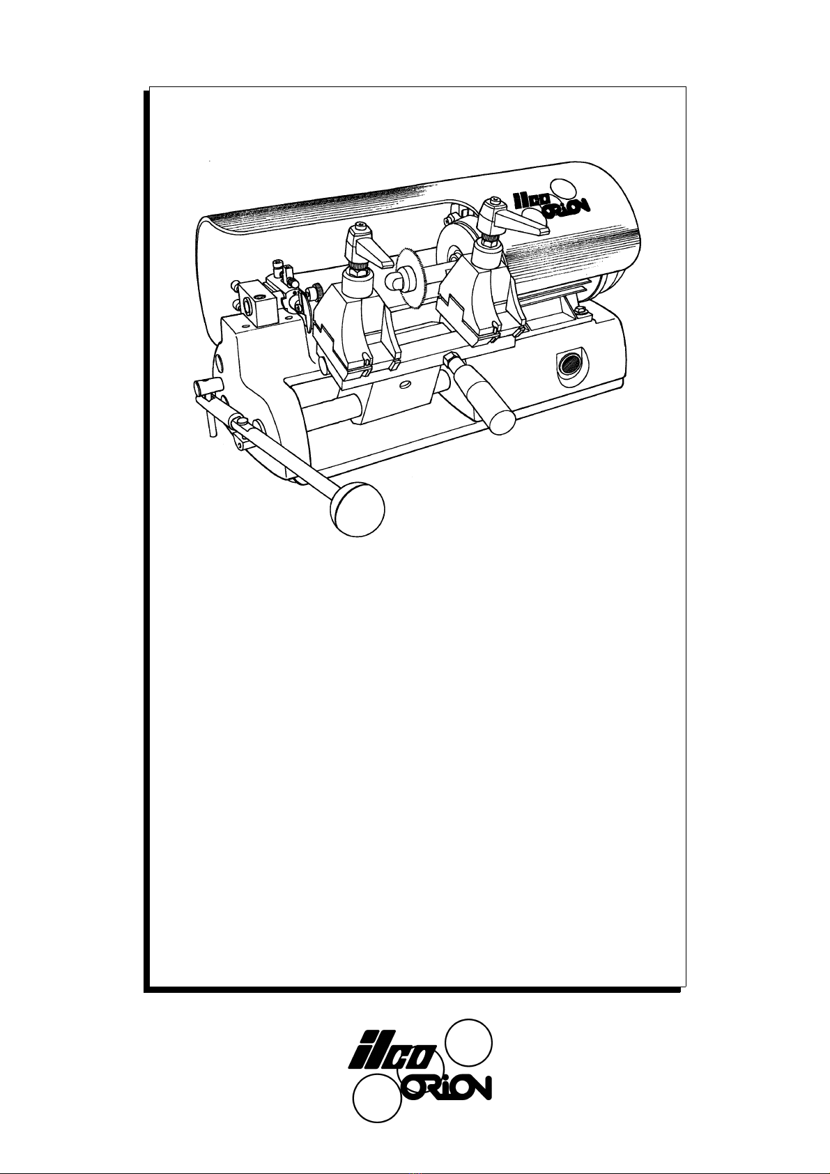
HALLEY BKA 2000

© 2002 SILCA S.p.A - Vittorio Veneto
This manual has been drawn up by ILCO ORION
All rights reserved. No part of this publication may be reproduced or used in any form or by any means (photocopying, micro-
film or other) without the written permission of ILCO ORION.
Edition: june 2006
Printed in Vittorio Veneto
by ILCO ORION
via Podgora, 20 (Z.I.)
31029 VITTORIO VENETO (TV) - Italy

INDEX
GUIDE TO THE MANUAL ......................................................................................................5
GENERAL INSTRUCTIONS ..................................................................................................6
1 TRANSPORT ..............................................................................................................7
1.1 Packing ............................................................................................................................7
1.2 Transport .........................................................................................................................7
1.3 Unpacking .......................................................................................................................7
1.4 Machine handling ............................................................................................................7
2 WORKING PARTS .....................................................................................................8
3 MACHINE DESCRIPTION ..........................................................................................9
3.1 Technical data .................................................................................................................9
3.2 Electrical circuit .............................................................................................................10
4 ACCESSORIES PROVIDED ....................................................................................11
5 MACHINE INSTALLATION AND PREPARATION ..................................................12
5.1 Checking for damage ....................................................................................................12
5.2 Environmental conditions ..............................................................................................12
5.3 Positioning .....................................................................................................................12
5.4 Description of work station ............................................................................................12
5.5 Graphics ........................................................................................................................13
5.6 Separate parts ...............................................................................................................13
5.7 Connection to the mains ................................................................................................13
6 REGULATION AND USE OF THE MACHINE ..........................................................14
6.1 Setting ...........................................................................................................................14
6.1.1 Adjusting the cutting depth ...............................................................................14
6.1.2 Setting the cutting spaces ................................................................................15
6.1.3 Setting the cutting height ..................................................................................15
6.2 Cutting operations .........................................................................................................16
6.3 Key cutting .....................................................................................................................16
6.4 BIT and DOUBLE BIT keys (side 1) ..............................................................................18
6.5 Pump keys (side1) .........................................................................................................19
7 MAINTENANCE ........................................................................................................20
7.1 Cutting tool replacement ...............................................................................................20
7.2 Tracer point replacement ..............................................................................................20
7.3 Replacing the fuses .......................................................................................................21
8 DISPOSING OF MACHINE .......................................................................................22
9 AFTER-SALES SERVICE ........................................................................................23
9.1 How to request service ..................................................................................................23

Operating manual - English HALLEY BKA 2000
5
GUIDE TO THE MANUAL
This manual has been produced to serve as a guide for users of the HALLEY BKA 2000 key-cutting
machine. Read it carefully; it is essential if you wish to operate your machine safely and efficiently
.
Consultation
The contents of the manual are divided into sections relating to:
- Transport and handling
- Description of machine and safety devices
- Proper use of the machine
- Maintenance
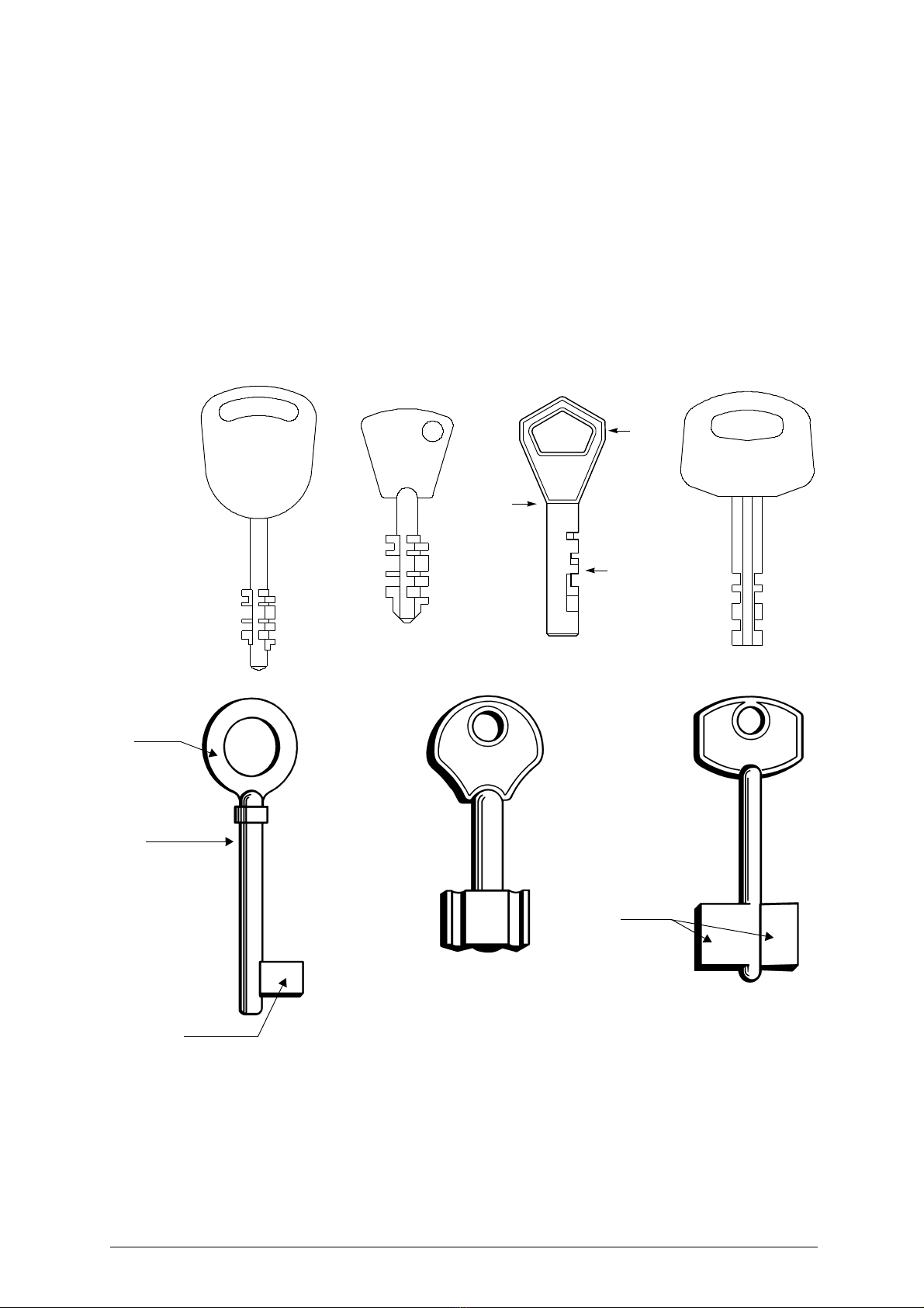
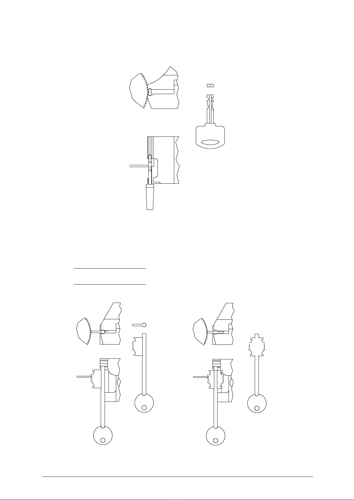
Technical terms
Common technical terms are used in this manual. To assist those with little experience of key cutting,
below is an illustration of the terms used for the different parts of keys
:
Fig. 1
1) Head
2) Rim
3) Tip
4) Cuts
2
1
4
Pump key
head
double
bit
stem
bit
Bit key Double bit key
3
HALLEY BKA 2000 Operating manual - English
6
GENERAL INSTRUCTIONS
The HALLEY BKA 2000 key-cutting machine has been designed according to the specifications of the
Machine Directives. From the design stage risks for the operator have been eliminated in all areas:
transport, regulation, cutting and maintenance.
The use of protective gogglesis compulsory during cutting operations, as indicated onthe machine itself
and in this manual.
The material used in the manufacture of this machine and
the components employed during use of
the machine are not dangerous and their use complies with standards
.
Use
The HALLEY BKA 2000 key-cutting machine must be installed and used in the way laid down by the
manufacturer, as illustrated in this manual.
If the machine is used differently or for purposes different from those described in this manual, the
customer will forego any rights he may have over Ilco Orion Furthermore, unforeseen danger to the
operator or any third parties may arise from incorrect use of the machine.
Negligence in the use of the machine or failure on the part of the operator to observe the instructions
given in this manual are not covered by the guarantee and the manufacturer declines all responsibility
in such cases.
It is therefore indispensable to read the operating manual carefully in order to make the best use
of the HALLEY BKA 2000 key-cutting machine and benefit from its potential.
Further risks
There are no further risks arising from the use of the HALLEY BKA 2000 key-cutting machine.
Protection and safety precautions for the operator
The HALLEY BKA 2000 key-cutting machine is built entirely to standards. The operations for which it
has been designed are easily carried out at no risk to the operator.
The adoption of general safety precautions (use of protective goggles) and observation of the
instructions provided by the manufacturer in this manual eliminate all human error, unless deliberate.
The HALLEY BKA 2000 key-cutting machine is designed with features which make it completely safe
in all its parts.
• Power supply
The key-cutting machine must be supplied with electricity by means of a safety device (standard with
230V key-cutting machines).
The plug must be earthed
.
• Start-up
The machine is started up by means of
:
1) the main switch on the safety device (standardwith 230V key-cuttingmachines, on request for other
voltages);
2) the ON switch, situated on the machine, which activates the machine motor.
• Maintenance
The operations to regulate, service, repair and clean the machine have been devised in the simplest
and safest way possible. There is no danger of removable parts being replaced wrongly or unsafely.
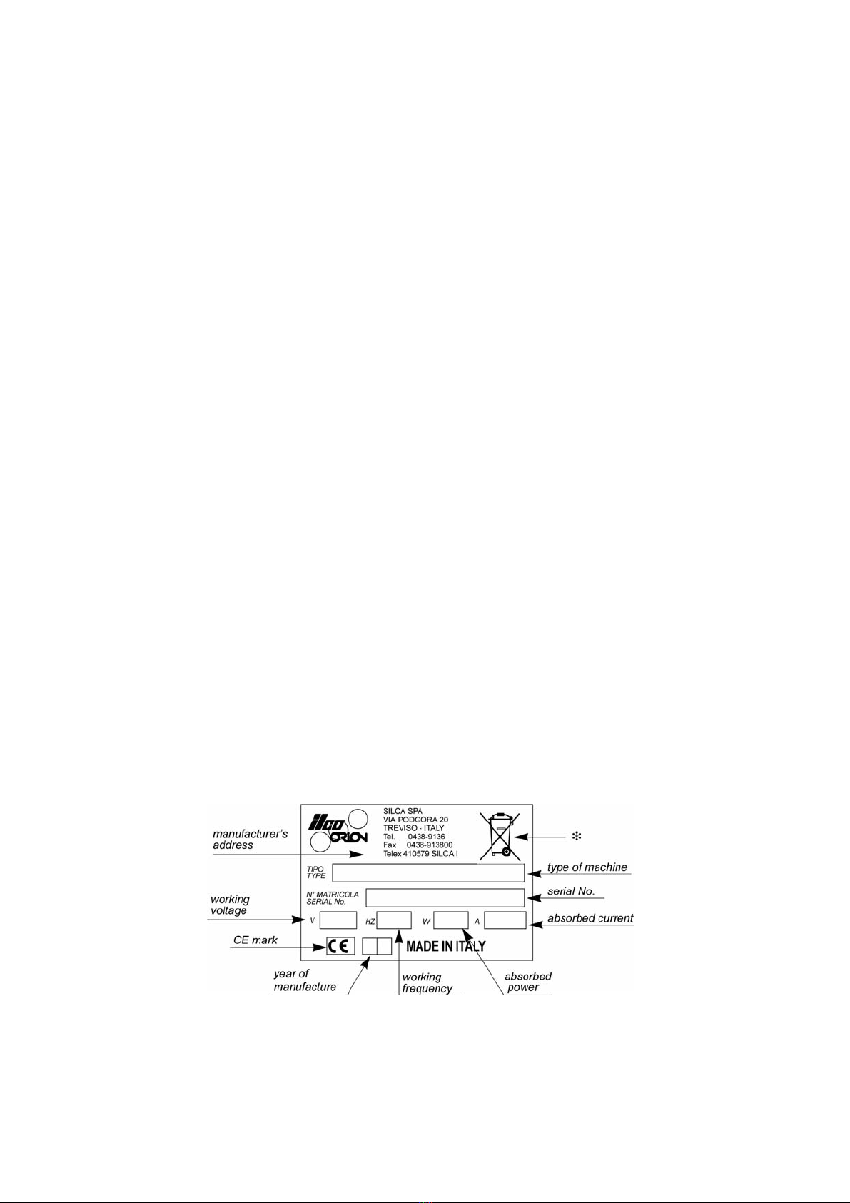
• Machine identification
The HALLEY BKA 2000 is provided with an identification label which shows the serial number (fig.2).
Fig. 2
(*) see chap. 8 DISPOSING OF MACHINE, page 22.
Operating manual - English HALLEY BKA 2000
7
1 TRANSPORT
The HALLEY BKA 2000 key-cutting machine is easily transported and is not dangerous to handle.
The packed machine can be carried by one person.
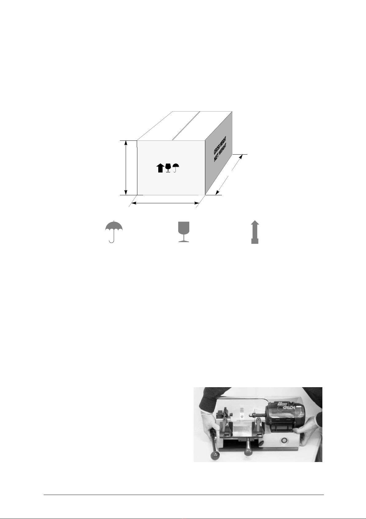
1.1 Packing
The HALLEY BKA 2000 key-cutting machine comes in a strong cardboard box, thedimensions of which
are shown in fig.3, designed to protect the machine and all its parts even when it is stored for long
periods.
Fig. 3
1.2 Transport
It is advisable to use the packing every time the machine is transported, as this will avoid knocks which
could cause damage to the machine, persons or things.
1.3 Unpacking
To remove the machine from the packing box:
1) cut the straps with scissors and remove,
2) open the box without damaging it as it may be used again (e.g. removals, dispatch to the
manufacturers for repairs or servicing),
3) check the contents of the box, which should comprise:
- 1 HALLEY BKA 2000 key-cutting machine;
- 1 safety device (standard with 230V key-cutting machines);
- set of documents, including: operating manual, spare parts list and guarantee;
- 1 set of accessories.
1.4 Machine handling
When the HALLEY BKA 2000 key-cutting
machine has been unpacked, place it directly
on its workbench.
This operation can be carried out by one
person,
firmly holding the base, and no
other part, to lift and carry the machine
.
Fig. 4
400 mm
600 mm
410 mm
Keep dry This side upHandle with care
HALLEY BKA 2000 Operating manual - English
8
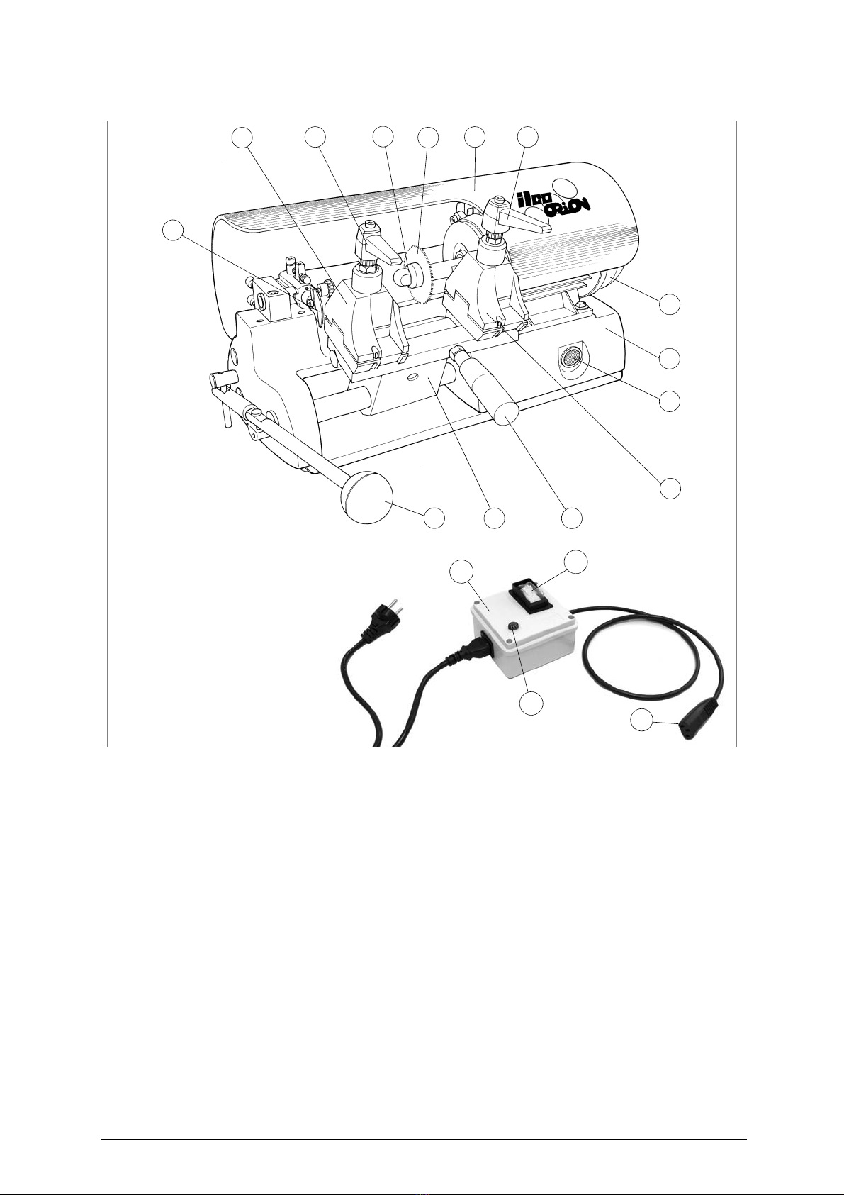
2 WORKING PARTS
Fig. 5
A-Mainswitch
B - Clamp carriage
C - Carriage lever
D-Base
E - Cutter nut
F - Lateral movement lever
G-Motor
H - Cutter protection
I - Key fastening knob
L - Clamp, tracer side
M - Clamp, cutter side
N - Tracer
O - Cutter
X - Safety device (standard with 230V key-cutting machines)
X1- Safety main switch
X2- Warning light
X3- Plug
N
LO
FC
D
M
A
G
B
EHI I
X1
X
X2 X3

Operating manual - English HALLEY BKA 2000
9
3 MACHINE DESCRIPTION
HALLEY BKA 2000 is a professional key-cutting machine for ABLOY
®
- ABUS GRANIT
®
/ PLUS
®
-
AVA CHUBB
®
- FORD CHUBB
®
- IFAM - LUMA
®
- BIT - DOUBLE BIT - PUMP keys. The machine
comprises the following main parts:
Safety device
(
standard with 230V key-cutting machines)
The device is connected to a power plug with a differential switch, power the key-cutting machine by
pressing the switch (X1).
The warning light (X2) illuminates to indicate voltage in the plug (X3).
ATTENTION: switch (X1) is electromagnetic, in the event of a power failure it goes out automatically. When
electricity is restored it must be reset manually to power the machine again by means of the plug
(X3).
Master switch
The motor starting button is placed on the right side of the motor of the HALLEY BKA 2000 key-cutting
machine.
ATTENTION:
the switch is illuminated to indicate that the machine is live
.
Motor
The HALLEY BKA 2000 has a direct drive motor (G). The transmission unit comprises the motor and
cutter is protected by a single cover (H).
Mobile unit
The mobile unit comprises a carriage (B) holding the clamps.
The carriage (B) is fitted to the translation shaft and is moved manually by the operator.
It has been designed to avoid the accumulation of cutting dust or chippings.
• Cutting tool (O)
The cutting tool is the part of the HALLEY BKA 2000 machine which cuts the key blank. The tool is in
HSS super rapid steel and is protected by a special cover (H) to ensure safe operation.
• Tracer point (N)
The tracer point is housed on the left-hand side of the machine base. Its depth settings are easily
regulated.
3.1 Technical data
ELECTRICAL PROPERTIES: 230V - 50Hz 190W 2A;
110V - 60Hz 190W-5A.
CUTTING TOOL: Super Rapid Steel (HSS)
MOTOR: One speed single phase;
230V-50Hz 1350 rpm 0,18 kW;
110V - 60Hz 1680 rpm 0,18 kW.
CLAMP: 2 sides
CARRIAGE MOVEMENT: manual
DIMENSIONS: width: 470 mm, depth: 350 mm, height: 260 mm
CUTTING NOISE: Lp (A) = max. 99,7 dB (A)
WEIGHT: Kg. 26
® Trade marks
HALLEY BKA 2000 Operating manual - English
10
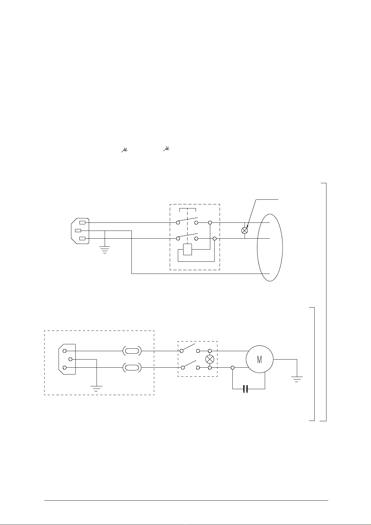
3.2 Electrical circuit
The HALLEY BKA 2000 key-cutting machine is provided with a single phase one-speed motor:
- 1350 rpm, consumes approximately 0.18 Kw, absorption 2A;
- 1680 rpm, consumes approximately 0.18 Kw absorption 4,3A
The main parts of the electric circuit on the HALLEY BKA 2000 are listed below:
1) Safety device inlet
2)
Safety main switch
3)
Warning light
4)
Wiring clip
5) Machine inlet
6) Rapid fuses 4A (230V) - 10A (110V)
7) Illuminated switch
8) Motor: 230V a.c. 50Hz - 110V a.c. 60Hz
9) Condenser 8 (230V) - 20 (110V)
Safety device (standard with 230V key-cutting machines)
FF
110V
230V
3
brown
blue
yellow-green
brown
blue
OUT
IN
4
1
2
5
6
6
78
9
Machine inlet
blue
black
black brown
Operating manual - English HALLEY BKA 2000
11
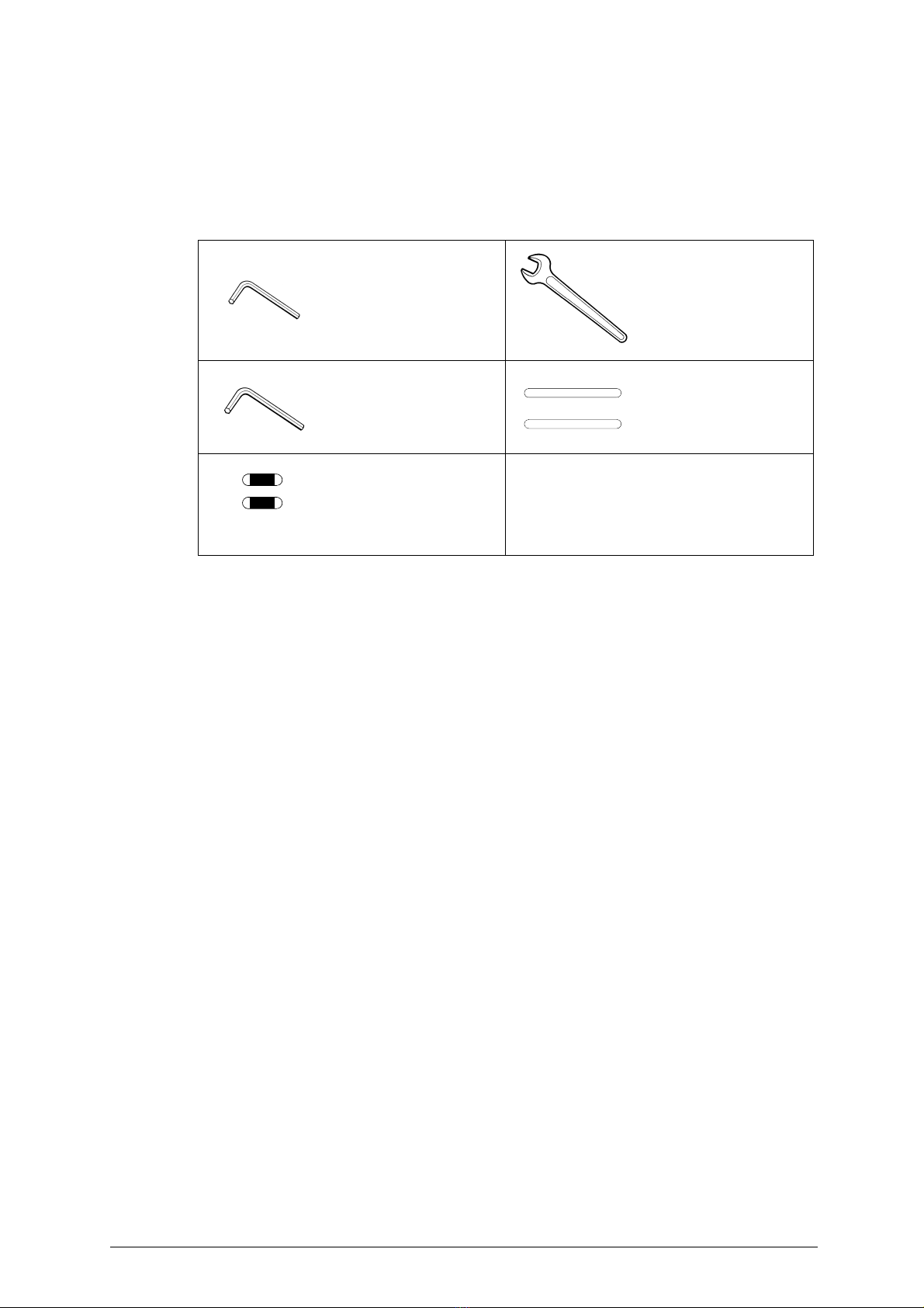
4 ACCESSORIES PROVIDED
To ensure trouble-free working with the HALLEY BKA 2000, it is advisable to always have certain spare
parts on hand.
It is advisable to always have a tool box containing: tools, cutting tools, and small replacement parts.
HALLEY BKA 2000 is supplied with a full range of accessories. The accessories provided by Ilco Orion
are all that is necessary to carry out the operations for which the machine is designed.
code
D300221ZZ
2 mm ALLEN KEY
code
DMS200340
13/17/19 mm SPANNER
2 pcs
code
D300223ZZ
3 mm ALLEN KEY
code
DEM306054
Setting up pins 6 x 50 mm
2 pcs
code
D301185ZZ
(230V)
FUSES 5x20 4A-rapid
code
D309997ZZ (110V)
FUSES 5x20 10A-rapid
HALLEY BKA 2000 Operating manual - English
12
5 MACHINE INSTALLATION AND PREPARATION
The HALLEY BKA 2000 key-cutting machine can be installed by the purchaser and does not require
anyspecial skills.However, somechecks andpreparationfor useneed tobe carriedout bythe operator.
5.1 Checking for damage
The HALLEY BKA 2000 is solid and compact and will not normally damage if transport, unpacking and
installation have all been carried out according to the instructions on the packing box.
However, it is always advisable to check that the machine has not suffered any damage.
5.2 Environmental conditions
To ensure that the best use is made of the key-cutting machine, certain parameters must be borne in
mind:
- damp, badly ventilated sites should be avoided.
- the conditions for the machine are:
- temperature: between 0 and 40°C
- relative humidity: approx60%
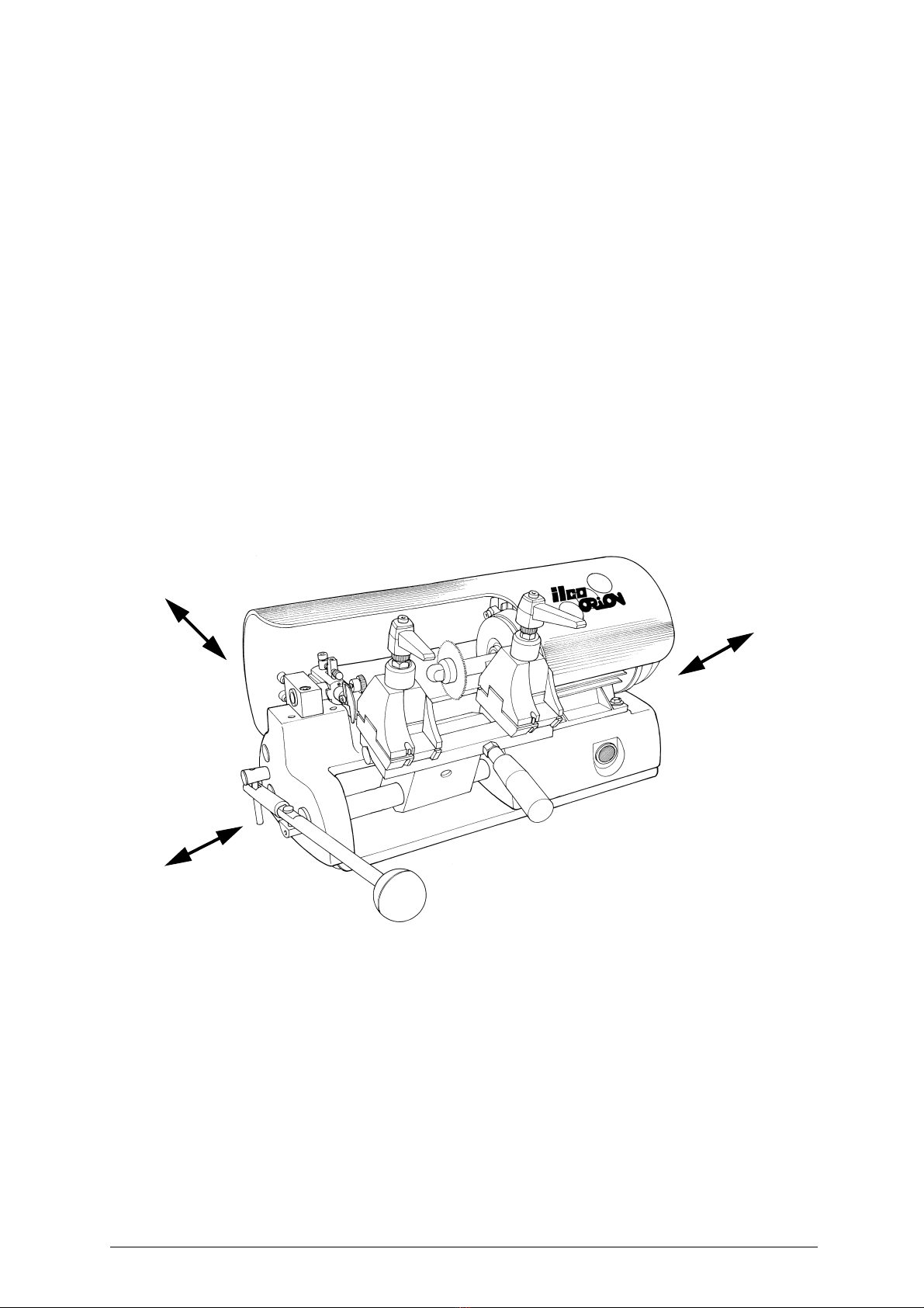
5.3 Positioning
Place the machine on a horizontal surface, solid enough to take the weight (26 Kg). To facilitate
operation and maintenance, install the machine with a clearance of at least 300 mm on all sides (fig.6).
Check that the weight of the machine is evenly distributed over the four feet; horizontal positioning
prevents vibrations during operation.
ATTENTION: ensure that the machine voltage is the same as that of the mains, which must be properly
earthed and provided with a differential switch.
Fig. 6
5.4 Description of work station
The machine needs only one operator, who has the following controls at his/her disposal:
• Master switch (A), placed on the left-hand side of the motor; provided with a warning light
indicating that the machine is live.
• Carriage lever handle (C).
• Lateral movement lever (F).
300mm
300mm
300mm
Operating manual - English HALLEY BKA 2000
13
5.5 Graphics
5.6 Separate parts
Thedetachableparts of themachineare packedseparatelyandmust befittedto the HALLEYBKA 2000
by the operator, as follows:
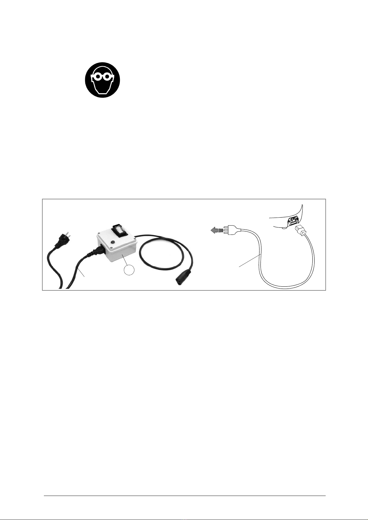
Power cable
230V version:
first connect the safety device (X) to the key-cutting machine and the power cable then connect the free
end of the power cable to the power mains (Fig. 7).
110V version:
connect the key-cutting machine and the power cable then connect the free end of the power cable to
the power mains (Fig. 7).
Fig. 7
5.7 Connection to the mains
It is extremely important for the operator’s safety to ensure that the key-cutting machine is connected
to the power mains with the right voltage and
by means of a properly earthed differential switch
.
THE USE OF PROTECTIVE GOGGLES
IS COMPULSORY
power cable
power
mains
power cable
X
power
mains
HALLEY BKA 2000 Operating manual - English
14
6 REGULATION AND USE OF THE MACHINE
The cutting tool on the HALLEY BKA 2000 is used to cut the key blanks and must be periodically
checked and replaced. Periodically, and whenever the cutting tool is replaced, check the key-cutting
machine settings, to ensure perfect machine efficiency.
6.1 Setting
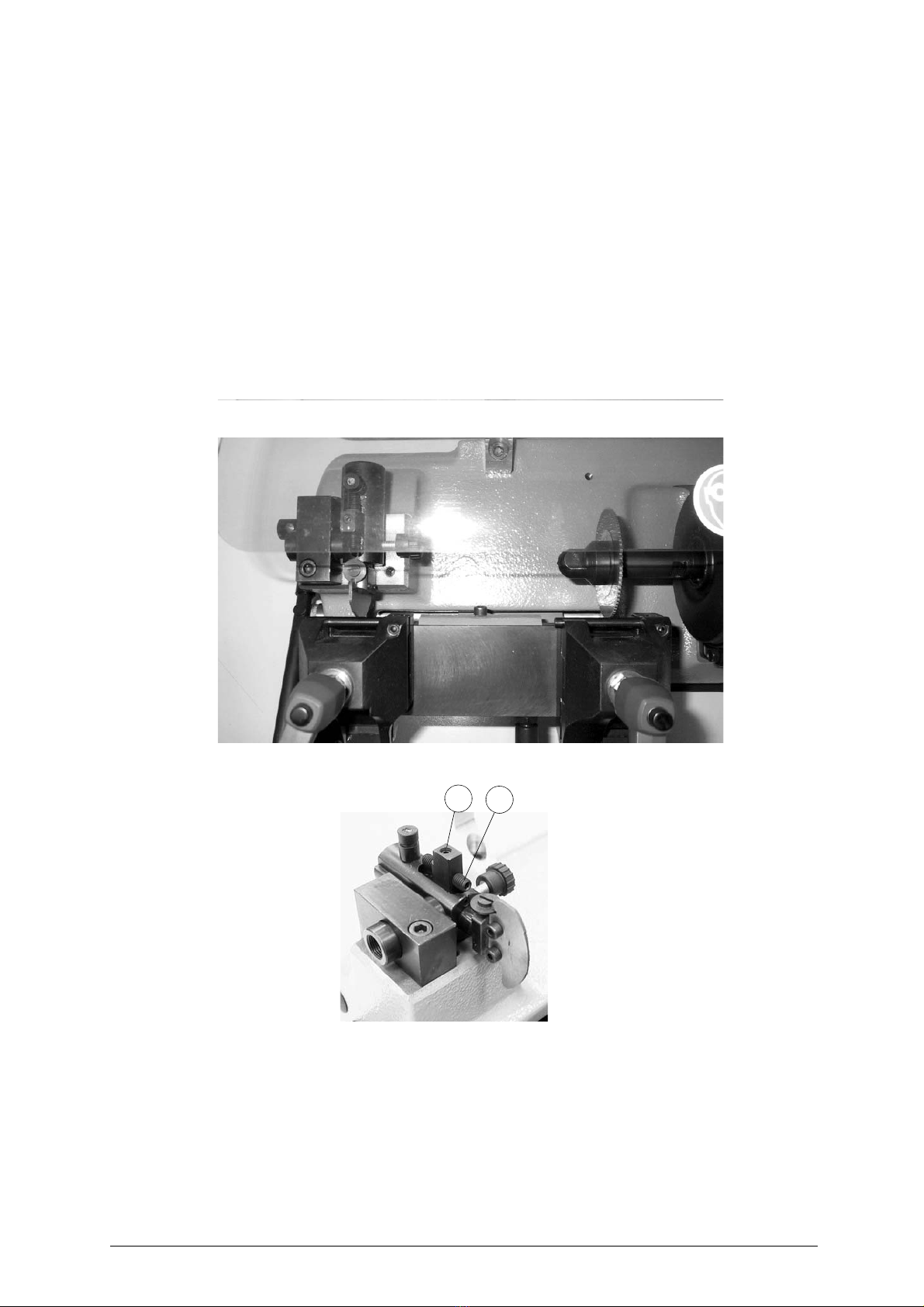
6.1.1 Adjusting the cutting depth
1) Insert the supplied gauges horizontally in the clamp housings (side 1) (fig.8).
2) move the carriage and make sure the tracer is well pressed against the gauge.
3) turn the cutter manually.
4) the cutting depth of the machine is correct when the cutter skims the gauge freely. Otherwise
proceed as follows:
- loosen the screw (J1) (fig.9).
- turn the screw (K1) (tighten it or loosen it until the cutter skims the gauge).
- fasten the screw (J1) (fig. 19, page 20).
Fig. 8
Fig. 9
K1
J1
Operating manual - English HALLEY BKA 2000
15
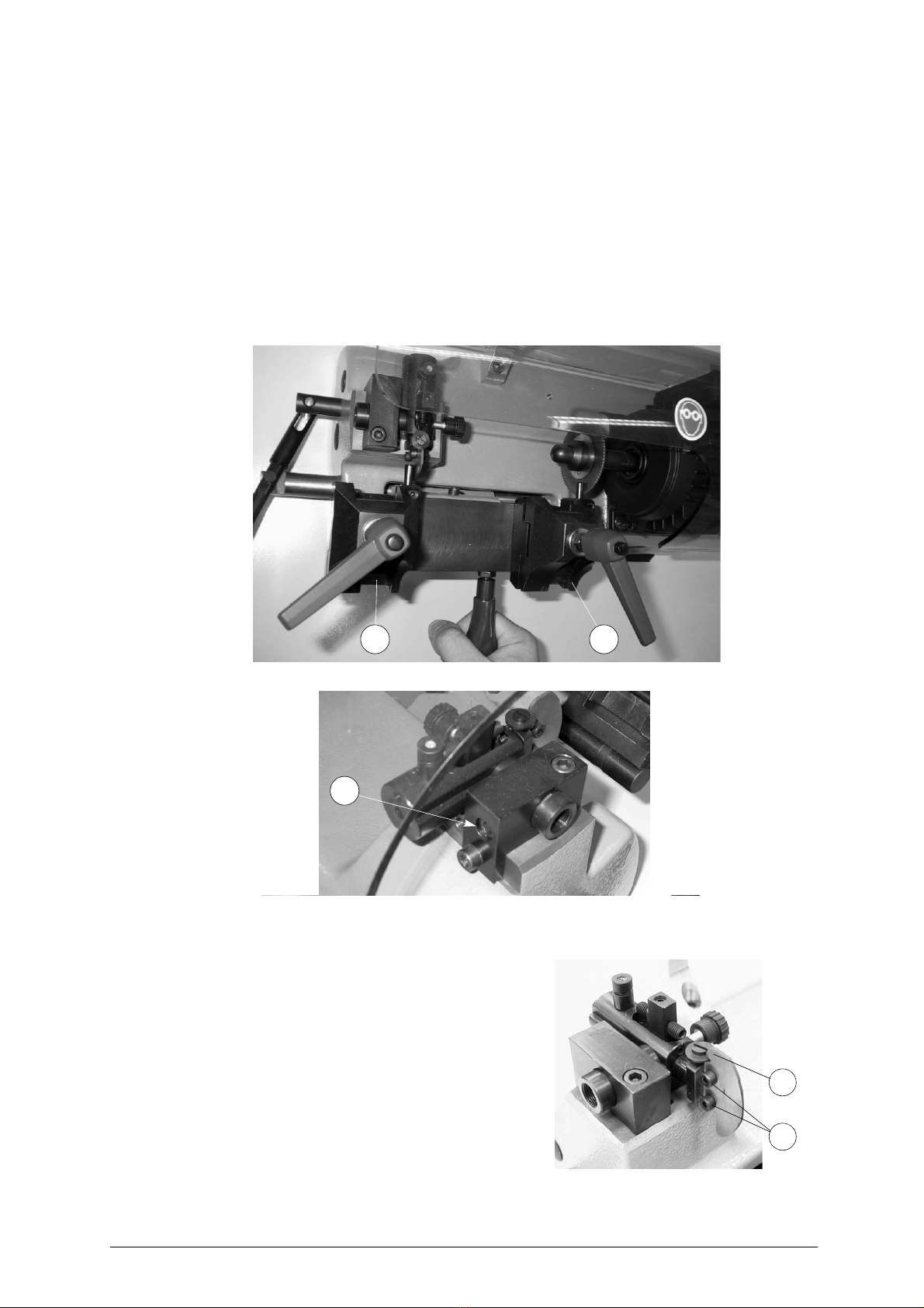
6.1.2 Setting the cutting spaces
ATTENTION: first carry out depth gauging then this gauging operation.
1) Insert the supplied gauges vertically in the clamps (side 1) (fig. 13, page 16).
2) move the clamp carriage until the tracer touches the gauge (fig.10).
3) turn the cutter manually.
4) the cutting interval is correct when the cutter skims the gauge in the right clamp (M). Otherwise
proceed as follows:
- loosen the screw (N1) of the tracer unit (fig.11).
- move the tracer unit next to the gauge in the left clamp (L).
- fasten the screw (N1).
- make sure the above mentioned condition occurs before the adjustment of the machine can be
considered correct.
Fig. 10
Fig. 11
6.1.3 Setting the cutting height
As for depth gauging. The cutter must skim the gauge
evenly, independently of the point of contact with the
tracer point.(in the centre, at the top, at the bottom). If
this is not so, loosen the screws (K) and adjust screw (J)
until ideal gauging is achieved (fig.12).
Fig. 12
L M
N1
K
J
HALLEY BKA 2000 Operating manual - English
16
6.2 Cutting operations
To work in complete safety, pay special attention to the following recommendations:
• Always work with dry hands.
• Check that the machine is properly earthed.
• Use the protective goggles, even if the cutting tool is fitted with a protective shield.
• Start the motor only when all the operations with the carriage have been carried out
(securing keys, etc.).
• Keep hands away from the cutting tool when in motion.
1) After having connected the machine to the mains, press the main switch (A) (fig. 5, page 8).
2) move the clamp unit towards the cutter unit using the lever (F).
3) for cutting the keys, use one of the sides of the clamp according to the type of key (chap. 6.3, page
16). Turn the clamp to the desired side; proceed as follows:
a) loosen the clamp fastening knob (I) by turning it anticlockwise until the pins protrude from the
guide.
b) turn the clamps (L) and (M) and position them as desired.
c) tighten the clamp fastening knob (I) until the clamps are fastened.
6.3 Key cutting
1) Position the sample key into the left clamp (L) and fasten it; position the key blank into the right (M)
and fasten it.
2) turn the machine on using the switch (A).
Important: move the carriage by raising the knob (C), this makes it move towards the cutter with
the key tilted thus aiding the cut, using the lever (F).
3) carry out the cut.
4) there may be different types of key to cut and therefore different references. The keys are to be
positioned in the clamps in the way described in fig.14,fig.15, fig.16 and fig.17.
Fig. 13
12
SIDE 2
Key-cutting:
- ABLOY®
- ABUS GRANIT / PLUS®
- AVA CHUBB®
- FORD CHUBB®
- IFAM®
- LUMA®
SIDE 1
Key-cutting:
- BIT KEYS
- DOUBLE BIT KEYS
- PUMP KEYS

HALLEY BKA 2000 Operating manual - English
18
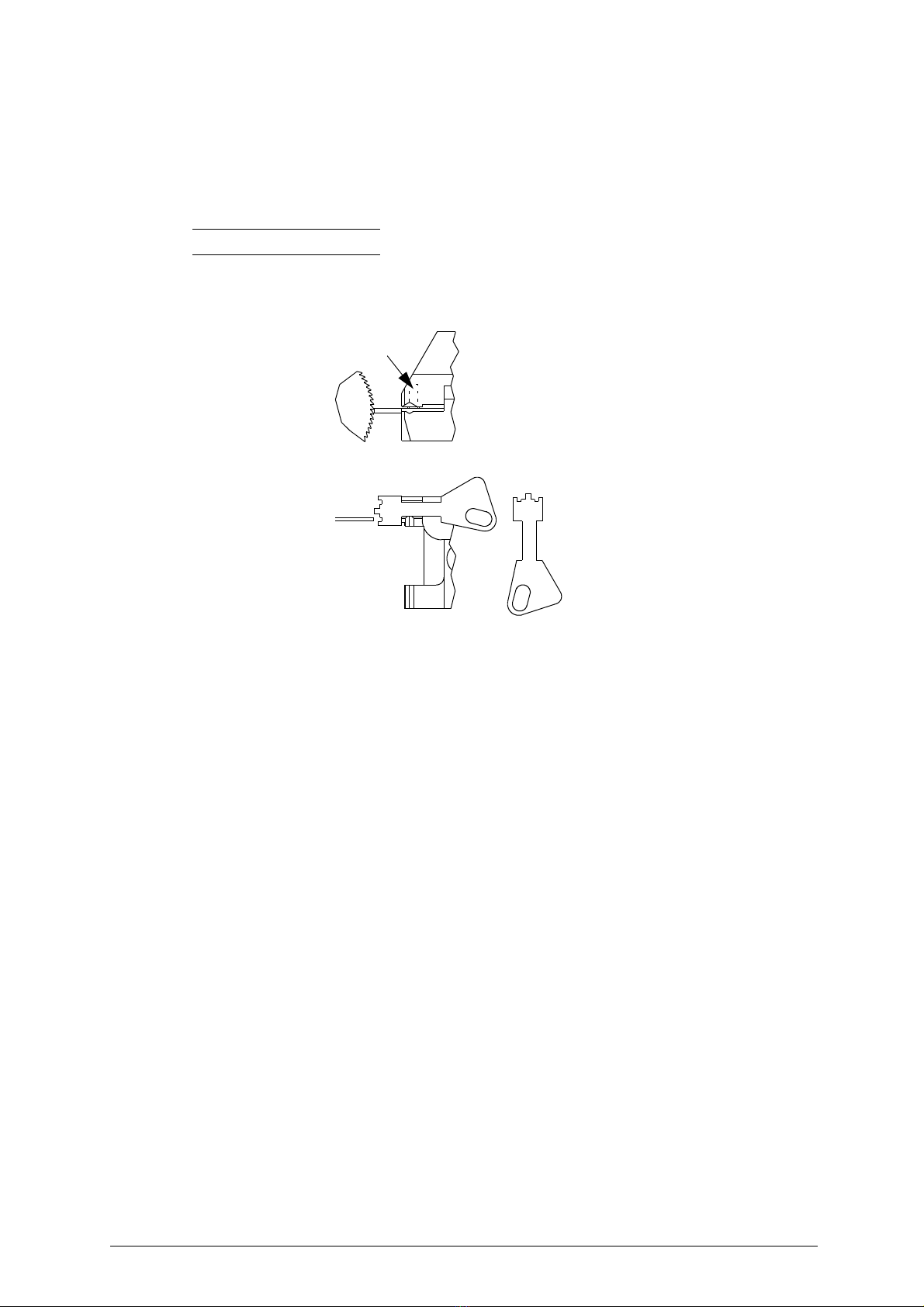
Fig. 15: keys with tip reference (side 2)
1) place the tip of the key against the reference pin.
2) fit the key in the vertical position.
Fig. 15
6.4 BIT and DOUBLE BIT keys (side 1)
1) Place the sample key into the left clamp (L) and fasten it, place the key blank into the right clamp
(M) without fastening it.
2) using the (F) and (C) levers, move the bit of the key towards the tracer.
3) place the bit of the key to be cut against the cutter and fasten it.
4) loosen the carriage and turn the machine on using the (A) switch.
Important: move the carriage by raising the knob (C), this makes it move towards the cutter with
the key tilted thus aiding the cut.
5) carry out the cut.
Round off the cuts by tilting the (C) knob from top to bottom.
Fig. 16
LUMA®
BIT KEY DOUBLE BIT KEY
Operating manual - English HALLEY BKA 2000
19
6.5 Pump keys (side1)
1) Loosen the clamp fastening knob (I) raise it and turn it to the desired position.
2) insert the sample key into the “V” shaped housing of the left clamp (L), make sure it presses against
the side of the clamp and fasten it.
3) in the same way fasten the key blank in the right clamp (M).
4) carry out the cut.
Important: for flat pump keys proceed as follows:
5) place the key in the clamp without fastening it.
6) fasten the key using the screw “X” situated at the top of the clamp.
Fig. 17
PUMP KEY
X
HALLEY BKA 2000 Operating manual - English
20
7 MAINTENANCE
Although the HALLEY BKA 2000 key-cutting machine does not require special maintenance, it is
advisable to check and, if necessary, replace the parts subject to wear (cutting tool, tracer point).
Replacement is simple and can be carried out by the operator.
CLEANING
: it is advisable to use a soft brush to keep the carriage and clamps free of chippings from
cutting operations.
ATTENTION: DO NOT USE COMPRESSED AIR!
Before starting any type of maintenance (checks or replacements), read the instructions below:
• never carry out maintenance or servicing with the machine switched on.
• always remove the mains plug.
• follow all the instructions in the manual to the letter.
• use original spare parts.
• always check that any screws or nuts removed when replacing a piece are properly
tightened.
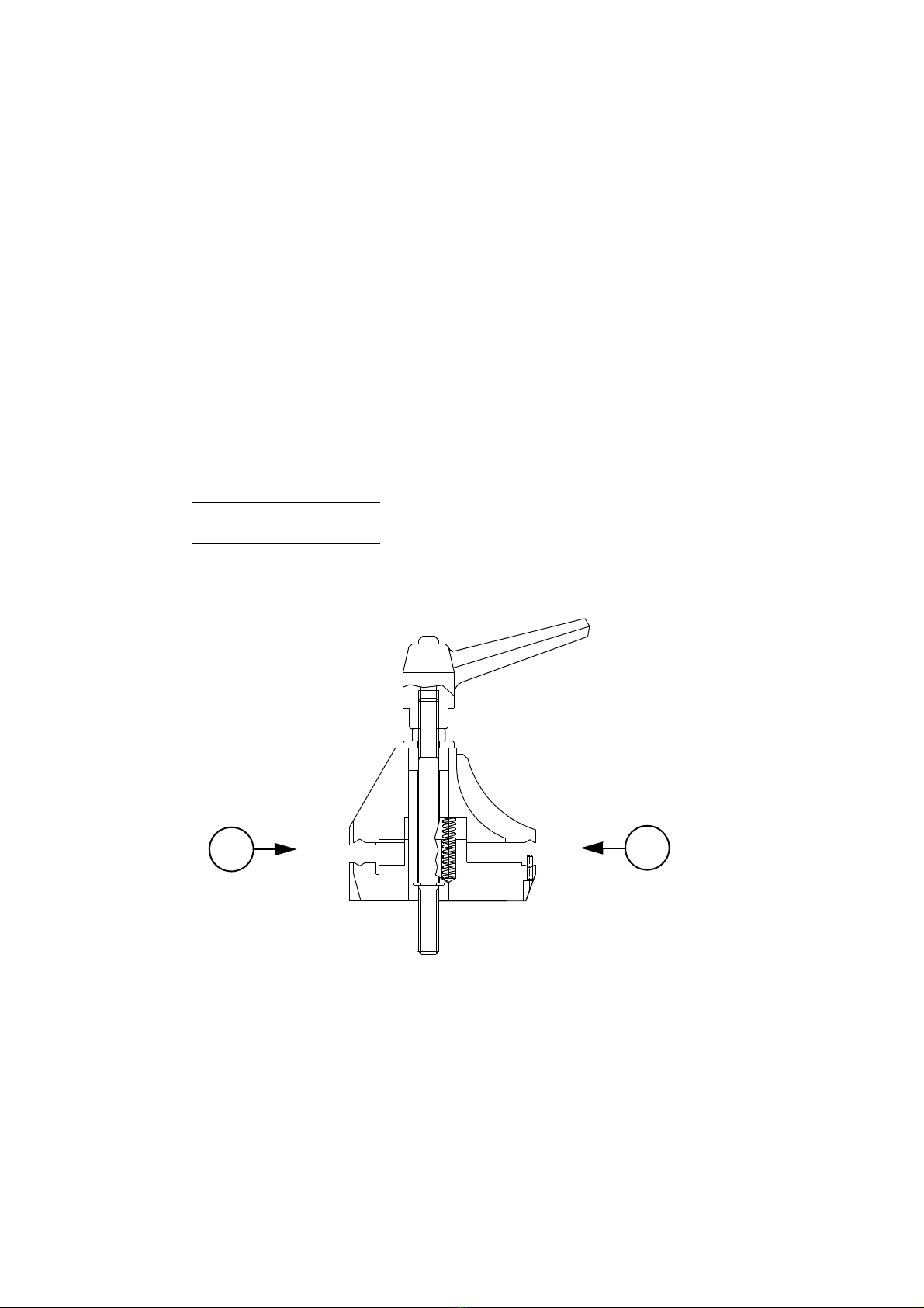
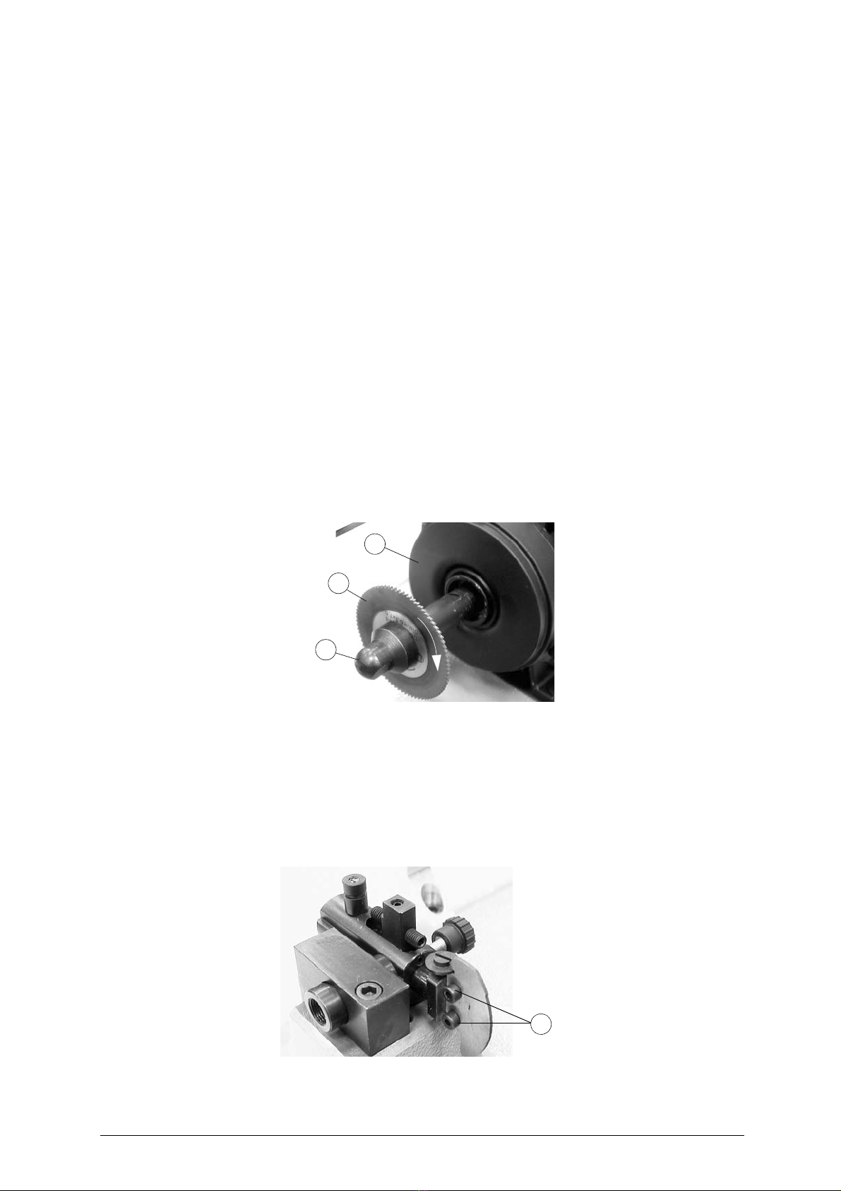
7.1 Cutting tool replacement
Using the supplied tools proceed as follows:
ATTENTION: remove the mains plug.
1) Place the 13 mm spanner onto the cutter shaft.
2) place the 13 mm spanner onto the cutter fastening (E) nut.
3) loosen the (E) nut by turning it clockwise (fig.18).
ATTENTION: left hand thread.
4) remove the (E) nut, the (O) cutter and clean the shaft.
5) insert the new cutter,
check its direction
of rotation and screw in the (E) nut anticlockwise.
Fig. 18
7.2 Tracer point replacement
To replace the tracer point (N), proceed as follows (fig.19):
ATTENTION:
unplug the machine from the mains
.
1)
Loosen and remove the tracer point locking screws
(K).
2)
remove the tracer point
.
3)
fit the new tracer point
.
4)
re-gauge the machine as described in
chap. 6, page 14.
Fig. 19
G
O
E
K
Table of contents
Other Ilco Orion Industrial Equipment manuals


