ILCO Unican 008A User manual
English INSTRUCTION MANUAL
IMPORTANT! Read these instructions before you use your new 008A Key Machine.
Ensure that all safety recommendations are followed!
See page 2 for instructions.
Español INSTRUCCIONES
ADVERTENCIA: lea estas instrucciones antes de usar su nueva duplicadora de llaves modelo 008A.
¡Asegúrese de que se respetan todas las recomendaciones de seguridad!
Vea la página 13 para las instrucciones.
Français MANUEL D’INSTRUCTIONS
IMPORTANT! Veuillez lire ces instructions avant d’utiliser votre nouvelle machine à tailler les clés 008A.
Vous assurer de suivre toutes les recommandations de sécurité !
Voir page 22 pour des instructions.
008A
®

This manual is registered and applies specifically to the
machine which carries this serial number. It properly
identifies your model and assures you will receive correct
parts, if and when you require replacement parts. Retain
this manual in a safe place. It’s the only one of its kind. If
ownership of this machine is transferred, this service
manual should accompany the machine.
When seeking service information about this machine,
refer to Model No. 008A and the part number desired
(see pages 6 to 8). Note that many parts are not
interchangeable with other ILCO UNICAN machines.
ENGLISH
2
CONTENTS
Warranty ........................................................................................2
Safety Information........................................................................3
Introduction ..................................................................................4
Unpacking......................................................................................4
Operating Parts (Illustrated) ......................................................5
Operating Parts Identification (Names and Part Numbers)..5
Exploded View ............................................................................6
Exploded View Parts List ............................................................8
Proper Key Cutting Techniques ................................................8
How to Duplicate Keys ..............................................................9
The Cutting Operation ..............................................................10
Replacements and Adjustments ..............................................11
ONE YEAR LIMITED WARRANTY
ILCO UNICAN warrants to the original buyer of any
new model 008A machine that it will repair or
replace, at its option, any part of any machine which
proves, to the reasonable satisfaction of ILCO
UNICAN, to have defects arising from the faulty
manufacture of the machine or from defective
material or components, during a period of one (1)
year from the date of shipment of the machine by
ILCO UNICAN, provided that the machine is
returned by prepaid transport to ILCO UNICAN or
to its authorized representative before the expiry of
the warranty period together with a detailed
description of the alleged defect(s). ILCO UNICAN
may, at its discretion, elect to refund the purchase
price allowable to the part affected, or to issue a
credit if the price therefore remains unpaid.
ILCO UNICAN sells precision-made machines. The
buyer assumes all risks, and ILCO UNICAN shall not
be liable for any reason, if the machine has been
subjected to improper installation, improper use,
improper or inadequate maintenance, negligence, if
any unauthorized modification or alteration is made
to the machine, or in case of accident. For greater
certainty, any machine not operated in accordance
with ILCO UNICAN’s printed instructions or
operated beyond its rated capacity shall not be
covered by this or any other warranty.
Any and all warranties made by ILCO UNICAN on
any machine, product, or component thereof shall be
effective only if and for so long as the buyer complies
with all payment obligations pursuant to the buyer’s
accepted and acknowledged order. Failure to meet
such payment obligations shall void all warranties and
not extend the period of time for which such machine,
product of component thereof is warranted irrespective
of whether or not payment is eventually made.
These warranties are in lieu of and not in addition to
any other warranty of condition, expressed or implied,
including without limitation merchantability, fitness for
a particular purpose or latent defects. The buyer
releases ILCO UNICAN from any liability for any
reason other than a breach of its warranties hereunder.
The liability of ILCO UNICAN shall in no case,
including negligence, exceed the purchase price of the
defective machine, nor shall ILCO UNICAN be liable
for any personal injuries, property damage or
consequential damages.
Use only genuine ILCO UNICAN replacement parts
on this machine!
Serial number : ______________________

Electrical Safety
•(120Voltmodels)Yourmachineisdesignedtooperate
using 120 Volt A. C. 60 Hz. electrical current. It is
supplied with a three-prong power plug which should
be used with a properly grounded three-prong outlet
only. Do not defeat the safety purpose of the plug by
modifying or using with non-grounded outlets!
•Toreduceriskoffireorelectricalshock,donotexpose
or operate machine in damp or wet locations.
•Electricalproblemsshouldbereferredtoqualified
repair technicians. If the machine is under warranty,
contact ILCO UNICAN at the address printed on the
cover. (ILCO UNICAN also offers repair service for
out-of-warranty machines. Contact ILCO UNICAN
for details.)
•Alwaysunplugthemachinebeforeremovingthe
hood or changing the cutter wheel.
WARNING – SAFETY NOTICE
3
IMPORTANT - Please read carefully before operating machine.
Safety begins with education, and continues with proper
application. All personnel who operate your machine
should read the supplied Operator’s Manual for
information on how to properly operate it. The likelihood
of accidents and miscuts will be greatly reduced.
General Safety
•Safetyglassesmustbeworntoreducethepossibility
of eye injury while operating or in the immediate
vicinity of key cutting equipment.
•Alwaysturnmachineoffbeforemakingadjustments
or inserting or removing keys.
•Machineshouldbelocatedinanareaaccessibleonly
by authorized operators. Location must be such that
customers and other personnel are not subject to
potential injury from “flying chips”.
•Donotdefeatsafetyfeaturesbuiltintoyourmachine.
Removal or modification of safety shields, cutter
guards, and other safety devices should be strictly
forbidden.
•Atnotimeshouldthemechanically-drivenpartsof
the machine be touched while it is in operation. The
operator should take care to ensure that loose-fitting
clothing, long hair, etc. are kept from the area of
machine operation.
•Yourmachinehasbeenspeciallydesignedandbuilt
for key cutting purposes only and should be operated
according to the Operator’s Manual. All other uses are
strongly discouraged as potentially dangerous, and
should not be attempted! Such use will immediately
void the machine’s warranty.
•Somestateshavespecificagerestrictionconcerning
the operation of certain types of equipment. Check
local and state ordinances for compliance.
Grounding Instructions
•Intheeventofamalfunctionorbreakdown,
grounding provides a path of least resistance for
electric current to reduce the risk of electric shock.
This machine is equipped with an electric cord that
has an equipment-grounding conductor and a
grounding plug. The plug must be plugged into a
machine outlet that is properly installed and
grounded in accordance with all local codes and
ordinances.
•Donotmodifytheplugprovided-ifitwillnotfitthe
outlet, have the proper outlet installed by a qualified
electrician.
•Improperconnectionoftheequipment-grounding
conductor can result in a risk of electric shock. The
conductor with insulation that has a green outer
surface (with or without yellow stripes) is the
equipment-grounding conductor. If repair or
replacement of the electric cord or plug is necessary,
do not connect the equipment-grounding conductor
to a live terminal.
•Checkwithaqualifiedelectricianorservicepersonnel
if the grounding instructions are not completely
understood, or if in doubt as to whether the machine
is properly grounded.
•Useonly3-wireextensioncordsthathave3-prong
grounding plugs and 3-pole receptacles that accept
the machine’s plug.
•Repair or replace damaged or worn cords
immediately.

Congratulations!
You’ve purchased a superior key cutting machine.
INTRODUCTION / UNPACKING
4
After removing your 008A key from the shipping carton,
it shold be set on a level workbench and wiped free of all
rust proofing oil. The machine is adjusted at the factory
and test keys have been cut on it, but it is recommended
that you check the adjustments to make sure they have
not slipped or shifted during transit (see page 12
”Adjustment For Depth of Cut”).
The model 008A manually operated key machine you’ve
just purchased incorporates the latest improvements in
design for key duplicating machines of its type.
The machine features two-way vise jaws designed to
accomodate virtually any standard cylinder key, limiting
the need for adaptors. Even double-sided automotive
keys can be duplicated with ease. The reverse side of the
vise jaw is ideally suited to gripping these keys and is
capable of gripping them in the groove or milling for
enhanced clamping performance when necessary (see
illustration on page 9).
Accurate, portable, easy to operate and maintain, the
model 008A delivers excellent performance at an
economical price!
Unpacking Instructions
The 008A has been engineered to duplicate cylinder
(paracentric) keys. It is not intended or designed for any
other purpose. The machine operator assumes all liability
when using this machine in a manner inconsistent with
its stated design purpose. Refer to page 3 for complete
safety information before operating the machine.
ILCO UNICAN strongly recommends the use of
protective eye glasses or goggles when operating this
machine, or when in the vicinity of the machine while it
is being operated. Protective eye wear prevents injuries!
The machine should be turned off before loading or
unloading keys.
When the key machine is operating, be careful not to
bump the vise jaw or carriage against the cutting wheel
as this will cause damage to the cutter, jaw, or carriage.
Refer to pages 6 and 7 for illustrations.
Safety
Aseriesofcutkeysaresuppliedwithyourmachine.
These keys were cut on your machine and represent the
result of our quality inspectors work before approving
your machine for shipment. The keys are reproductions
of factory dimensioned pattern keys and are accurate to
within .002” or less. You can save these keys and use
them as standards to check the accuracy of cuts in the
keys you make. Duplicating a key and then using a key
micrometer or caliper to compare the actual depth of the
cuts on both the duplicate and the pattern key will allow
you to see if your machine is cutting too deep or too
shallow, thus indicating that an adjustment of the cutter
guide is necessary.
Test Keys
The model 008A is designed to be portable and thus
easily moved from location to location as the need arises.
There is however, a provision for securing the machine to
a work bench or other suitable mounting surface. Simply
install the supplied wood screws through the 3
countersunk holes on the top surface of the machine base
when a more permanent installation is desired.
Bench Mounting
Part No Identification
008-1 Carriage
008-3X Vise jaw assembly (2)
008-8 Wing Nut (2)
008-23 Carriage shaft
008-38 23RF Cutter
008-49 Cutter Guide (stylus)
008-55 Adjusting screw
008-56 Key gauge
008-85 Safety hood
008-48 Drive Belt
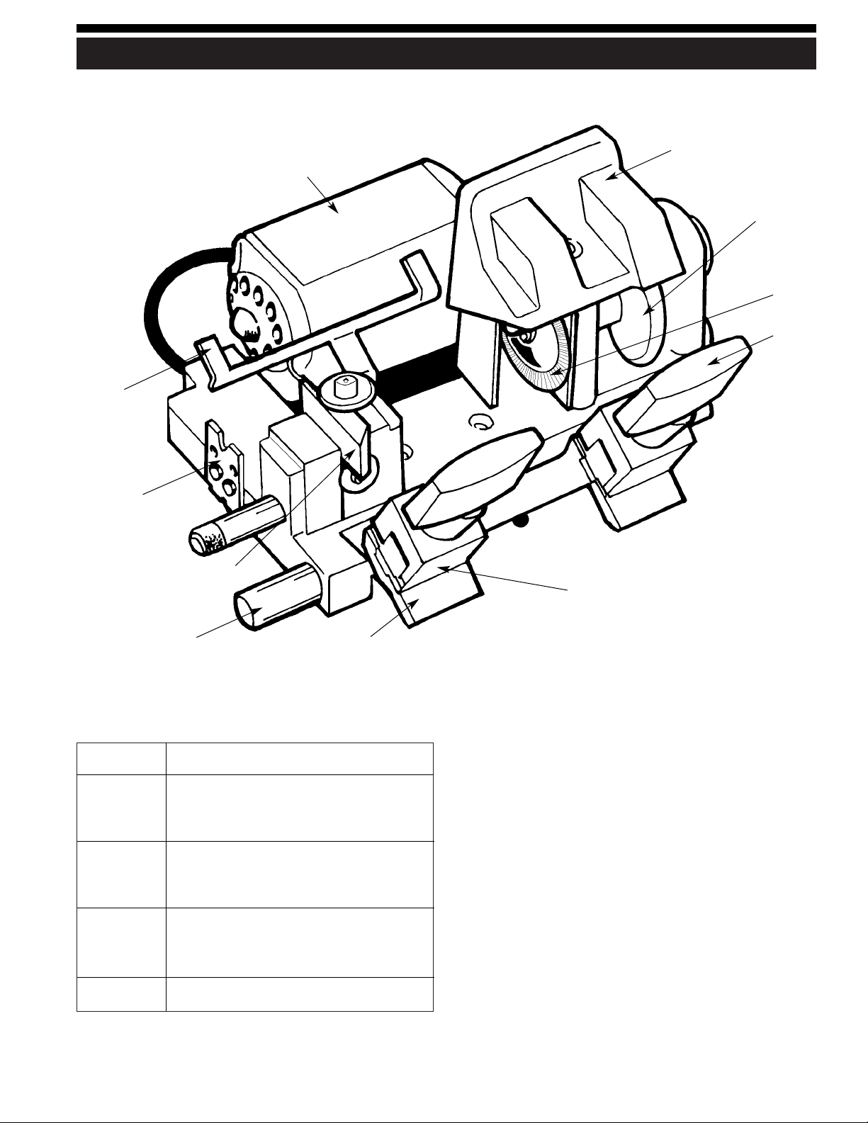
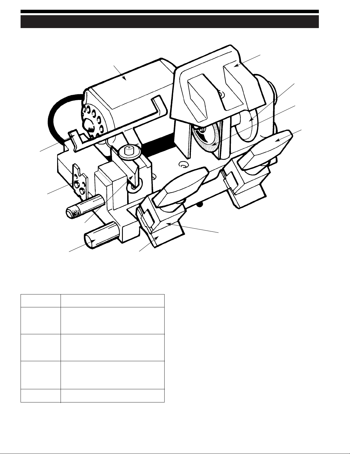
OPERATING PARTS
5
Motor assembly
Safety hood
Drive belt
Cutter
Wing nut
Vise jaw
Carriage
Carraige shaft
Cutter guide
Key rake
Key gauge
Operating Parts Identification
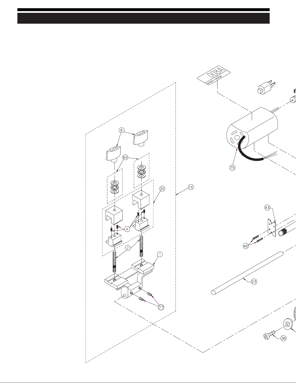
EXPLODED VIEW /VISTA EN DETALLE / SCHÉMA ÉCLATÉ
6
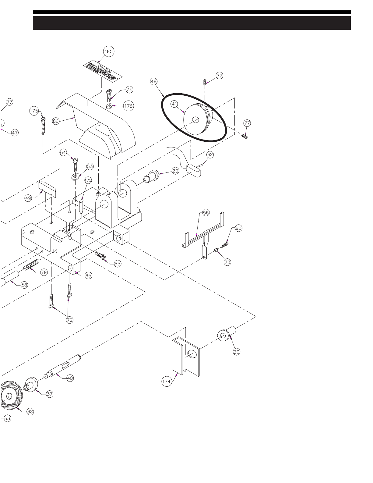
EXPLODED VIEW /VISTA EN DETALLE /SCHÉMA ÉCLATÉ
7

Ref. Part No. Description
1008-1Carriage
1X 008-1X Carriage Assembly
2008-2CarriageStud
3X 008-3X Vise Jaw Assembly
4008-4ViseJawSpring
6X 008-6X Thrust Bearing Set
8008-8WingNut
20 008-20 Cutter Shaft Bushing
23 008-23 Carriage Shaft
36 008-36 Cutter Shaft Screw (10-32 x 3⁄4” LH)
37 008-37 Cutter Spacer
38 008-38 23RF Cutter
40 008-40 Cutter Shaft
41 008-41 Cutter Shaft Pulley
43 008-43 Key Rake
46 008-46 Key Rake Screw (8-32 x 3⁄8”)
47 008-47 Motor Pulley
48 008-48 Drive Belt
49 008-49 Cutter Guide, (stylus)
53 008-53 Binding Washer
54 008-54 Cutter Guide Binding Screw
Ref. Part No. Description
55 008-55 Adjusting Screw
56 008-56 Key Gauge
58 008-58 Key Gauge Shaft
60 008-60 Key Gauge Screw (8-32 x 1⁄2”)
62 008A-62 Off/On Power Switch
65 008-65 Main Base, Machined
73 008-73 Key Gauge Lockwasher, #8)
74 008-74 Safety Hood Screw, (10-32 x 3⁄8”)
75 008A-75A 115V Motor Assy. (008A version)
76 008-76 Motor Mounting Screw (10-32 x 9⁄16”)
77 008-77 Set Screw (10-32 x 1⁄4”)
79 008-79 Key Gauge Spring
86 008A-86A Safety Hood/Belt Guard
160 008-160 Caution Label
174 008-174 Chip Deflector
175 008-175 Mounting oval head wood screw, (10 x 13⁄4")
176 008-176 Cutter Guide Pin
177 008-177 Safety Hood Washer
NS 008-IM Instruction Manual
NS 12V motor with connecting cable
NS 008A-66 Main Base, machined
EXPLODED VIEW PARTS LIST
8
Even though your 008A key machine is designed to make
key cutting efficient and accurate, operator skill is
important. The actual mechanics of placing keys within
the vise jaws is simple to learn, but there are some basics
that must be followed. A properly adjusted key machine,
used by someone who ignores good key cutting
techniques will NOT produce a good key. The way a
person clamps a key into the vise jaws is critical to the
accuracy of the duplicated key.
Remember - the real purpose of a duplicate key is to
operate the lock for which it was intended. If customers
return keys, you should reexamine your cutting
techniques and adjustment of the machine.
Here are some important operating tips:
1. Vise jaws - clean them regularly so that no metal chips
lie under the keys. It is essential that both keys lie flat
across the entire width of each vise jaw. Neither key
should be tilted.
2. Do NOT use pliers or other tools to tighten the vise
jaws. Firm hand pressure is sufficient.
3. Keep the carriage shaft free of metal chips. A thin film
of oil can be applied to it. The carriage should be free
to move without binding.
4. NEVER touch the shoulder of a key to the side of the
cutter guide. This will cause the shoulder of the key
blank to touch the side of the cutting wheel. When this
happens, some of the metal will be cut away from the
shoulder of the key blank. If the resulting duplicated
key is duplicated two, three, four times over, an error
will accumulate and cause a non-operating key. Do
not grind away the shoulder.
5. Don’t run the cutter into the vise jaw; this will dull the
cutter, and reduce cutter efficiency.
6. Keep the cutter clean. Don’t let any foreign objects or
instruments blunt it. This cutter is a precise cutting
tool and should be handled with care.
7. Lubrication of moving parts is important. The carriage
spindle should be lubricated with a thin film of oil,
removing excess with a clean dry cloth. The
lubrication procedures should be performed every 2-3
weeks depending upon machine usage. (5-7 drops of
a lightweight machine oil such as “3-in-1” or
equivalent is sufficient.)
Proper key cutting techniques
Refer to pages 6-7 for illustration
Using the two-way vise jaws
Your 008A machine is equipped with versatile Super Jaw
1 two-way vise jaws. Their unique clamping surfaces will
securely grip virtually any typical cylinder key, while
reducing the need for adaptors.
The vise jaws have two clamping surfaces; standard and
“X”. The standard position is identified by a 1⁄4” wide slot
milled into the vise surface. The “X” position is identified
by the presence of the letter X stamped on the upper half
of the vise jaw. When choosing which position to use
observe the following guidelines:
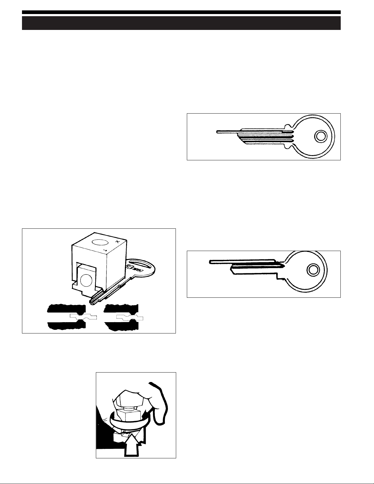
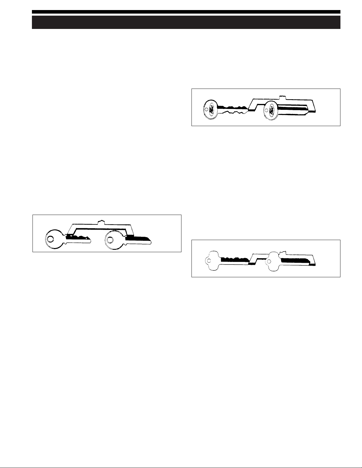
Standard position — for holding regular cylinder keys
such as house keys, single-sided automotive keys,
padlock keys, with one or two shoulders. Also used for
“Ford style” double-sided keys which do not have a
groove along the center of the key blade.
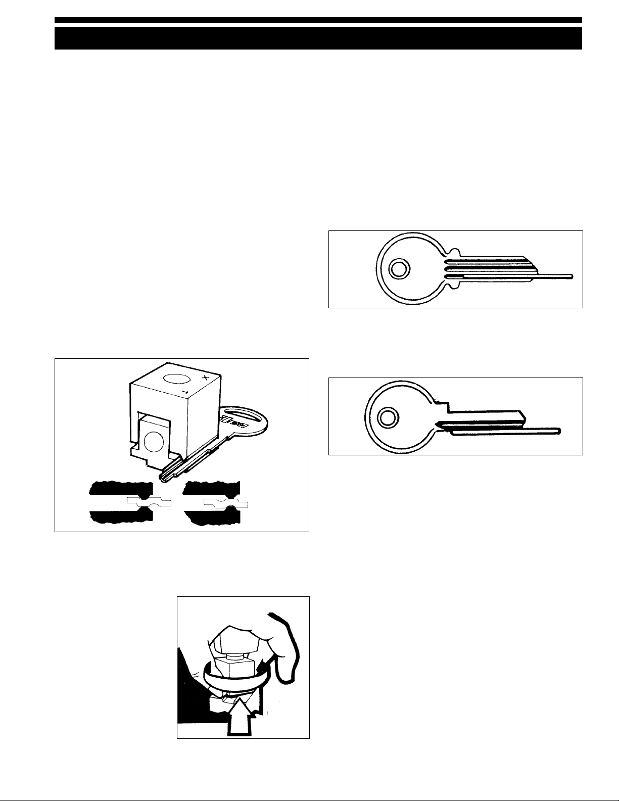
X position — Ideal for holding most double sided
convenience keys used on many current automobiles.
Grips these keys by the grooves rather than the blade
edge where the cuts are located (see fig. 1).
To rotate the vise jaws from one position to the other,
loosen the wing nuts three or four turns from the
“closed” position. Using the thumb and forefinger, grasp
the bottom section of each vise.
Lift this section up and
free of the carriage. Rotate
the vise jaws one-half
turn and reseat lower
section into groove of
carriage (see fig. 2). Both
vise jaws must be rotated
to the same position;
standard or X!
HOW TO DUPLICATE KEYS
9
How and when to use straight wires
Occasionally, you may encounter keys with rounded or
wide milling (grooves) that tend to tip in the vises when
the wing nuts are tightened. If this occurs, you should
position a “straight wire” (supplied in the machine’s tool
pack) into the milling or groove closest to the back of the
key (see fig. 3A). With the straight wire positioned as
shown, insert the key in the vise and tighten the wing nut
to secure it in place. This will prevent tilting from
occurring. An alternate method is to use the “X” side of
the vise jaws to grip the milling of such keys.
Some narrow keys with deep cuts require the straight
wire to be placed under the key. This raises the key out
from the vise to prevent the cutter from contacting the
vise jaws when making the deep cuts (see fig. 3B).
Figure 1
Figure 2
Figure 3A
Figure 3B
Lift…
rotate…
reseat

THE CUTTING OPERATION
10
Aligning keys in the vise jaws
Keys with shoulders
WARNING: Do not install or remove keys unless the
off/on switch is in the offposition.
Both the pattern key and the key blank must be properly
aligned and securely clamped in the vise jaws. To do this,
slide the machines’ carriage assembly towards the right
and position the appropriate key blank in the carriage’s
RIGHT vise jaw with the head of the blank pointing to
the left.
Ensure that the shoulder of the key blank is located
approximately 1⁄8” to the left of the vise jaw‘s left edge.
Holding the key blank firmly and level against the jaw,
tighten the wing nut. Position the pattern key in the
carriage‘s LEFT vise jaw in a similar manner only this
time allowing a 1⁄4” gap between the shoulder of the key
and the edge of the vise jaw.
Next lower the key gauge and position the carriage so
that the left edge of the gauge’s RIGHT prong contacts
the edge of the key blank’s shoulder (see fig. 4A).
Loosen the wing nut securing the pattern key and
reposition the key so that its shoulder is in contact with
the left edge of the LEFT prong of the key gauge.
Check to ensure that the pattern key and blank key‘s
shoulders are snug against the key gauge and both keys
positioned level (not tilted) in the vise jaws. Retighten the
wing nut.
Aligning keys in the vise jaws
Keys without shoulders
On keys such as the Ford double-sided key, which do not
have conventional shoulder, the tip of the key is used as
the aligning point (see Fig. 4B). Clamp the blank key in
first and move the machine carriage to the left. Lower the
key gauge and position the carriage so the tip of the Ford
key touches the key gauge. Install and align the pattern
key in the left vise jaw in the same manner.
“Best” and “Falcon” type keys do not have a
conventional shoulder but have a recessed tip and the
key gauge is used to align the recessed tips. After
clamping the blank key, the carriage is moved to the left
so that the key gauge can be lowered to contact the
recessed tip surface. The pattern key is aligned in the left
vise jaw and positioned to contact the edge of the key
gauge in the same manner (see Fig. 4C).
Figure 4A
Shoulder
Figure 4B Tip
Figure 4C Recessed tip
REPLACEMENTS AND ADJUSTMENTS
11
General Operating Sequence
WARNING: Do not install or remove keys unless the
off/on switch is in the offposition.
1. Rotate both vise jaws to the station suitable for the key
being duplicated.
2. Insert the blank key and pattern key into the vise jaws
using the appropriate method described under
“Aligning Keys in the Vise Jaws”. Be sure that both
keys are laying level in the vise jaws and are not tilted.
3. Lower the key gauge to align the keys using an
appropriate method as described under “Aligning
Keys …” found in the previous section (see page 10).
4. After the keys are aligned, return the gauge to its “up”
position.
5. Press the off/on switch to the “on” position.
6. Lift the carriage with both hands.
7. Move the carriage to line up the cutter guide with the
shoulder of the pattern key, then shift slightly away
from the shoulder. Do not permit the cutter to touch
the shoulder of the key blank.
8. Press in on the carriage, while guiding it to the left.
Carefully trace the cuts of the pattern key with the
cutter guide. The cutter will make a corresponding cut
in the key blank. When the cut closest to the tip of the
pattern key has been traced, retrace the cuts by
guiding the carriage to the right. This will clear away
any metal not removed during the initial pass over the
key blank.
9. Press the off/of switch to the “off” position. Remove
the duplicate key and remove any burrs that remain
by contacting the key lightly against the key rake.
10.Operating Tips - When duplicating a key, avoid an
irregular jerking motion in the movement of the
carriage. Acquire a smooth steady motion, using both
hands on the carriage to guide it. Apply the same
degree of pressure each time a key is duplicated.
Excessive pressure may cause “over-cutting”. It is
sometimes best to practice on a few keys until the
operator learns to impart a steady, uniform pressure to
the carriage.
Replacing the Cutter
The 23RF cutter used on this machine is 21⁄4” in diameter,
.250” thick (1⁄4”) and has a 1⁄2” hole. It’s a milling cutter,
made out of high speed steel. It has a flat left side, which
is excellent for making deep cuts, when these cuts are
next to the shoulder, such as on GM, Chicago, etc. No
warranty is placed on the cutter, operators should treat it
with care and avoid harsh usage. Do not force the
carriage up, causing the key blank to bang into the cutter,
and do not apply heavy pressure when cutting. Also, do
not let the cutter run into the vise jaw; this will dull the
cutter quickly.
As with any metal cutting instrument, the 23RF will dull
with usage. There are three ways to tell when a cutter
is dull and requires replacing:
1. Time - a dull cutter takes longer to make the cuts.
2. Sound - a dull cutter will emit a shrilly sound as it
runs across the key blank.
3. Burrs - a dull cutter will not cut away the metal but
will roll it away. When this occurs, there will be a
buildup of metal burrs on the underside of the key. If
this buildup is heavy, the cutter is dull. A sharp cutter
leaves little or no burrs.
To replace the cutter:
1. Remove screw which holds hood in place and remove
hood.
2. To remove the cutter, loosen cutter shaft screw using
allen wrench supplied with machine. IMPORTANT:
This is a left hand screw. Remove by turning in a
clockwise direction. Screwdriver slot is provided on
the opposite end of the shaft to aid in removal.
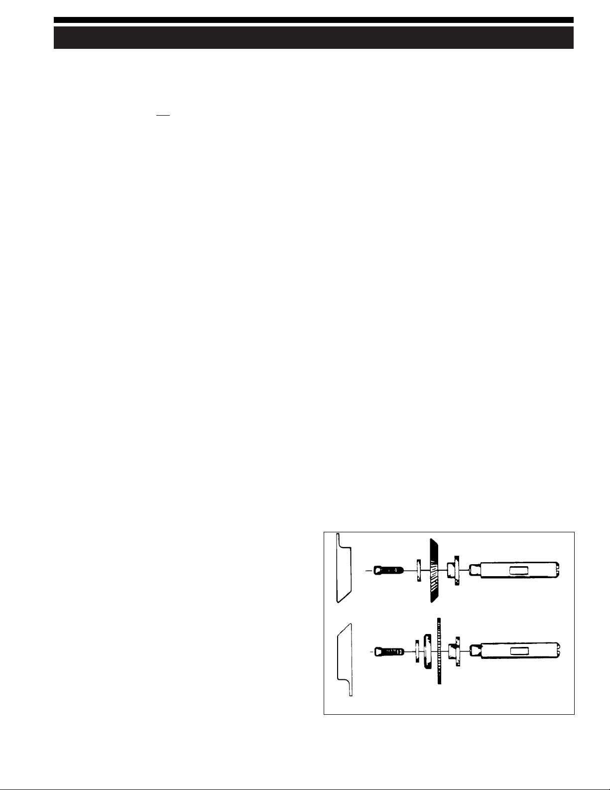
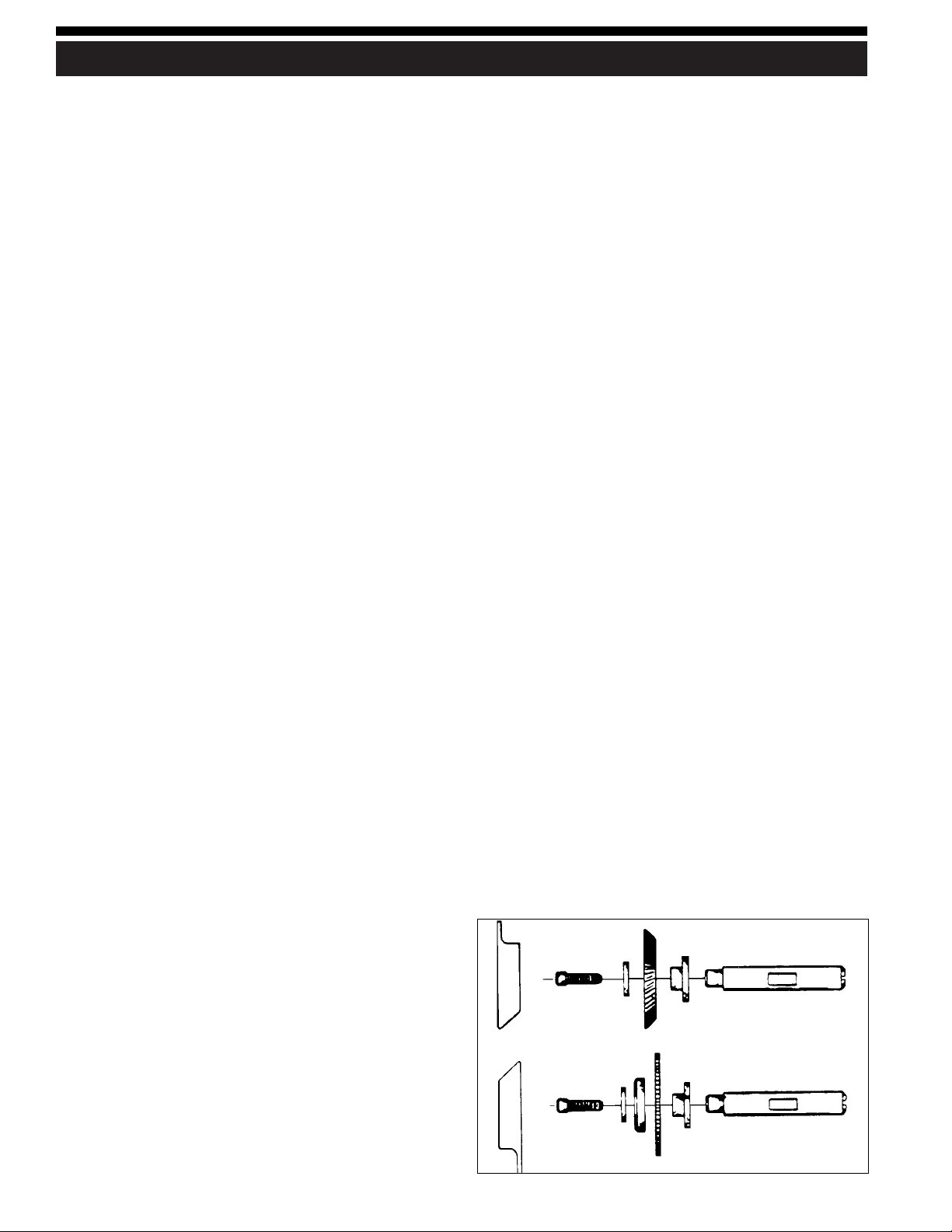
3. Remove old cutter and replace with new one. Be
careful to replace washers properly. Diagram below
shows placement of washers with standard 23RF
cutter and optional slotter.
23RF cutter
Slotter (optional, order 27X kit)

Adjusting for depth of cut
To ensure safety, UNPLUG machine from its power
source before adjusting for depth of cut. It’s imperative
that the key guide and the cutter be in the same plane,
that is, aligned to each other. If the cutter guide protrudes
further than the cutter, the resulting cuts in a key blank
will be too shallow and the duplicate key will not work.
Likewise, if the cutter guide is behind the cutter, the cuts
in the key will be too deep (see Fig. 6).
To check the depth adjustment, insert two identical key
blanks into the vise jaws, setting them flat in each vise. It
is not necessary to align the blanks. Then, raise the
carriage, positioning the left blank against the cutter
guide and the right blank against the cutter. Next, turn
the machine pulley by hand and note the right key blank.
The cutter should just barely graze the key blank when
the adjustment is correct.
No cutter is perfectly round so make one complete
rotation of the cutter before changing adjustment. There
will be a high point on the cutter; the adjustment should
be made to the high point. If the cutter does not touch the
key blank after one rotation, proceed to change the
adjustment.
To adjust cutter guide, loosen set screw on top of the
guide. With a flat screwdriver, turn adjusting screw in (to
increase depth of cut) and/or out (to decrease depth of
cut). Again, proper adjustment is achieved when the
cutter barely grazes the key blank.
REPLACEMENTS AND ADJUSTMENTS
12
Maintenance
1. The carriage spindle should be lubricated periodically
by wiping lightly with an oily rag. The cutter shaft is
lubricated by the oil impregnated bronze bearings.
After extended use, these bearings should be
lubricated with a light machine oil applied to their
end to assure continued smooth operation.
2. Keep the model 008A clean. The cutter should be kept
free of filings and dirt. A wire brush may be used for
this purpose, being careful not to chip or dull the
cutter. The motor should also be free of filings.
Compressed air is recommended for cleaning the
motor.
3. The machine should be picked up by the base, not the
carriage … as tempting as it seems. Alignment of the
carriage is critical for accurate duplication of keys and
this type of handling is not suggested.
Replacing the drive belt
1. Remove screw which holds hood in place and remove
hood.
2. Using allen wrench supplied with machine, loosen
both set screws located in cutter shaft pulley.
3. Slide cutter shaft to the left and remove cutter shaft
pulley and belt.
4. Place new belt and pulley in position and slide the
cutter shaft back to the right. Before tightening (2) set
screws in cutter shaft pulley, make sure cutter and
pulley are snug against bronze bearings in left
supporting post. This insures minimum end play.
Cleaning
Your machine should be kept clean of all filings and dust.
The most critical areas are the carriage jaws and shafts. A
one inch paint brush is ideal to brush these areas of the
machine. The shafts should be wiped periodically with a
lightly oiled cloth. We suggest brushing the jaws often as
even a single filing can alter the accuracy of the machine.
Figure 6

Este manual está registrado y se aplica específicamente a
la máquina que lleva este número de serie. Esto identifica
su modelo correctamente y asegura que usted recibirá las
partes correctas cuando las requiera. Guarde este manual
en un lugar seguro. Es el único de este estilo. Si esta
máquina cambia de dueño, debe entregar la máquina con
este manual.
Cuando solicite información de servicio en esta máquina,
refiérase al no. del modelo (008A) y a la parte deseada
(vea la página 17). Note que varias partes no son
intercambiables con otras máquinas ILCO UNICAN.
ESPAÑOL
13
CONTENIDO
Garantía........................................................................................13
Nota de seguridad......................................................................14
Introducción (al modelo 008A) ................................................15
Instrucciones de desembalaje ..................................................15
Partes operantes (ilustración) ..................................................16
Identificación de las partes operantes
(nombres y números de piezas) ..............................................16
Lista de piezas de la vista en detalle ......................................17
Técnicas correctas para cortar las llaves ................................17
Cómo duplicar llaves ................................................................18
Operación de corte ....................................................................19
Repuestos y ajustes ....................................................................20
Vista en detalle ..............................................................................6
GARANTÍA LIMITADA DE UN AÑO
ILCO UNICAN garantiza al comprador original de
una máquina modelo 008A nueva la sustitución o
reparación, según su criterio, de cualquier pieza que
tenga defectos de fábrica, de materiales o de
componentes, conforme al juicio razonable de
ILCO UNICAN, durante un período de un (1) año, a
partir de la fecha de envío desde ILCO UNICAN,
siempre y cuando la máquina haya sido devuelta con
porte pagado a ILCO UNICAN o a su representante
autorizado, antes de que se venza el período de
garantía y junto con una descripción detallada del
defecto alegado. ILCO UNICAN podrá, si así lo
decide, reembolsar el precio de compra
correspondiente a la pieza defectuosa o dar un crédito,
si el precio de dicha pieza no ha sido pagado todavía.
ILCO UNICAN vende máquinas fabricadas con
precisión. El comprador asume todos los riesgos, y el
fabricante no será de ninguna manera responsable, si
la máquina no ha sido instalada en forma correcta o
ha sido sujeta a un uso inadecuado, un
mantenimiento incorrecto o inadecuado, negligencia,
alteraciones o modificaciones no autorizadas, o si ha
ocurrido un accidente. En otras palabras: esta o
cualquier otra garantía no cubre ninguna máquina
que se haya hecho funcionar sin atenerse a las
instrucciones impresas de ILCO UNICAN o a la
capacidad nominal de la máquina.
Toda garantía otorgada por ILCO UNICAN para
cualquier máquina, producto o componentes tendrá
vigencia únicamente si el comprador cumple con
todas las obligaciones de pago, conforme al pedido
aceptado y confirmado por el vendedor. En el caso de
incumplimiento de pagos, toda garantía queda
anulada y no podrá prolongarse para esa máquina,
producto o componente, independientemente de si
los pagos se realizan con posterioridad.
Esta garantía sustituye pero no se agrega a cualquier
otra garantía de condición, explícita o implícita,
incluyendo pero no limitándose a la comerciabilidad,
adecuación para un fin particular o defectos ocultos.
El comprador libera a ILCO UNICAN de toda
responsabilidad que no se origine en una violación
de las condiciones expresadas en la presente
garantía.
La responsabilidad de ILCO UNICAN no deberá en
ningún caso, incluyendo los casos de negligencia,
sobrepasar el precio de compra de la máquina
defectuosa, ni cubrir lesiones personales, daños a la
propiedad o daños y perjuicios indirectos.
¡Use únicamente piezas de repuesto genuinas de
ILCO UNICAN para esta máquina!
Número de serie : ______________________________

ADVERTENCIA - NOTA DE SEGURIDAD
14
La seguridad comienza con la educación y continúa con
su aplicación apropiada. Todas las personas que operan
su máquina duplicadora de llaves deben leer el
«Manual del Operador» donde se informa cómo
operarla correctamente, así el índice de accidentes será,
sin duda, reducido.
Importante : por favor lea con atención antes de usar la máquina
Seguridad en general
•Siemprequeutiliceunamáquinaduplicadorade
llaves o esté en sus proximidades debe usar los lentes
de protección.
•Desconectelamáquinaantesdehacerajustes,ponero
sacar llaves.
•Lamáquinadebeestarlocalizadaenunáreadeacceso
restringido, donde solamente los operadores
autorizados puedan entrar. Esta medida evitará que
clientes u otras personas puedan sufrir daños con las
chispas desprendidas.
•Noretirelosequiposdeseguridadinstaladosenla
máquina. La remoción o modificación de protectores de
cualquier tipo debe estar terminantemente prohibida.
•Nuncatoquelaspartesmecánicasconlamáquinaen
funcionamiento. El operador también deberá tener
cuidado para que no entren en la máquina partes de su
ropa (mangas, hilos, etc...) como también cabellos largos.
• La máquina fue concebida para copiar llaves y debe
ser utilizada de acuerdo con el manual del operador.
Cualquier otro uso está prohibido por ser
potencialmente peligroso, por lo que no deberá
intentarse. Hacer otro uso de la máquina anulará
inmediatamente su garantía.
•Enalgunospaísespuedenexistirleyesquelimitenel
tiempo de vida útil de ciertos equipos. Verifique si
estas leyes existen en su país y si corresponden a su
máquina duplicadora de llaves.
Seguridad con la electricidad
•Lamáquinade120VCAy60Hzfuediseñadaparaser
usada con este voltaje. Viene con enchufe (macho) de
3 pernos que debe utilizarse en instalaciones
adecuadas, con conexión a tierra (enchufe hembra de
3 orificios). Nunca utilice la máquina en otro tipo de
instalación, ni modifique el sistema de enchufe
(macho) de tres pernos para usarlo en instalaciones sin
conexión a tierra (enchufe hembra de 2 orificios).
•Parareducirelriesgodechoqueseléctricos,noinstale
ni opere la máquina en lugares húmedos o mojados.
•Si la máquina presenta problemas eléctricos,
entréguela a técnicos calificados. Si su garantía está
vigente, contacte ILCO UNICAN, en la dirección que
aparece en la tapa. ILCO UNICAN también ofrece
servicio de reparación fuera de la garantía. Llámenos
para conocer más detalles.
•Siempredesconecte(desenchufe)lamáquinaantesde
sacar la tapa o cambiar la fresa.
Instrucciones para conectar a tierra
•Encasodemalfuncionamientoofalla,laconexióna
tierra suministra un camino de menor resistencia a la
corriente eléctrica para reducir el riesgo de choque
eléctrico. Esta máquina viene equipada con un cable
eléctrico que posee un conductor y un enchufe
debidamente equipados para la conexión a tierra. El
enchufe se debe conectar al tomacorriente
correspondiente que se encuentre instalado en forma
adecuada y puesto a tierra, de acuerdo con todos los
códigos y reglamentos locales.
•Nomodifiqueelenchufequesesuministra-sinose
adapta al tomacorriente, haga que un electricista
competente instale el tomacorriente apropiado.
•Laconexióninadecuadadelconductorpuederesultar
en un riesgo de choque eléctrico. El conductor con
aislamiento que posee una superficie exterior verde
(con o sin bandas amarillas) es el que sirve para
conectar el equipo a tierra. Si es necesario reparar o
cambiar el cable eléctrico o el enchufe, no conecte este
conductor a un borne vivo.
• Consulte con un electricista competente o con el
personal de servicio si no comprende bien las
instrucciones para la conexión a tierra o si no está
seguro de la apropiada conexión a tierra de la máquina.
•Usesolamentecablestriplesdeextensióncon
enchufes de 3 machos con contacto a tierra y
tomacorrientes de 3 orificios que acepten el enchufe
de la máquina.
•Repareocambieloscablesaveriadosodesgastados
inmediatamente.

INTRODUCCIÓN / INSTRUCCIONES DE DESEMBALAJE
15
¡Felicitaciones!
Acaba de comprar una máquina cortadora de llaves de calidad superior.
El modelo manual 008A que acaba de adquirir incorpora
las últimas mejoras de diseño para este tipo de
duplicadoras de llaves.
La máquina posee mordazas con dos posiciones,
diseñadas para sujetar casi todas las llaves cilindro
estándar, lo que reduce la necesidad de usar adaptadores.
Inclusive las llaves de doble cara para automotores
pueden duplicarse con facilidad. El dorso de la mordaza
sirve idealmente para sujetar estas llaves en la ranura o
partes fresadas en los casos en que se requiera una mejor
sujeción (véase la ilustración en la página 12).
¡Preciso, portátil, fácil de operar y mantener, el modelo
008A brinda un desempeño óptimo a un precio
económico!
La duplicadora 008A ha sido diseñada y debe usarse
únicamente para copiar llaves cilindro (paracéntricas). El
operador de la máquina asume toda responsabilidad, si
la usa para otro fin que no sea el mencionado y para el
cual ha sido diseñada. Antes de operar la máquina, véase
la página 14 para obtener toda la información sobre
cuestiones de seguridad.
ILCO UNICAN recomienda sin excepción el uso de gafas
protectoras para la persona que opera la máquina o se
encuentra en los alrededores de la misma mientras está
en funcionamiento. ¡Las gafas protectoras previenen las
lesiones! Antes de colocar o sacar las llaves, la máquina
debería estar apagada.
Mientras la máquina duplicadora funciona, tenga cuidado
de no golpear las mordazas o el carro contra la rueda de
corte, porque se dañará la fresa, la mordaza o el carro.
Consulte la vista en detalle en las páginas 6-7.
Instrucciones de desembalaje
Después de sacar la duplicadora 008A de la caja de
embalaje, se deberá instalar sobre un banco de taller que
esté a nivel y quitarle todo el aceite antioxidante. La
calibración es de fábrica y las llaves de prueba se cortaron
con la máquina, pero se recomienda que usted haga una
verificación para asegurarse de que no se ha descalibrado
ni movido durante el viaje (véase la página 21 “Ajuste de
la profundidad de corte”.)
Seguridad
Llaves de pruebas
La máquina viene con una serie de llaves cortadas por
ella y que representan la labor de nuestros inspectores de
calidad, antes de aprobar el despacho de la duplicadora.
Las llaves son reproducciones de modelos de fábrica y
tienen una precisión mínima de 0,002 pulg. Estas llaves
pueden guardarse y utilizarse como normas para
verificar la exactitud de los cortes en las llaves que
duplique. La duplicación de una llave y la utilización
posterior de un micrómetro o calibrador para comparar
la profundidad de los cortes en la llave duplicada y la
modelo le permitirá comprobar si su máquina hace cortes
demasiado profundos o muy superficiales, y si es
necesario ajustar la guía de la fresa.
Montaje en banco de taller
El modelo 008A es portátil y puede transportarse
fácilmente de un lugar a otro, según se necesite. No
obstante, es posible fijar la máquina sobre un banco de
trabajo u otra superficie apropiada. Cuando desee tener
una instalación más permanente, coloque simplemente
los tornillos para madera provistos en los 3 agujeros
avellanados de la parte superior de la base de la
máquina.
PARTES OPERANTES
16
No de pieza Identificación
008-1 Carro
008-3X Mordazas ensambladas (2)
008-8 Tuercas de mariposa (2)
008-23 Eje del carro
008-38 Fresa 23RF
008-49 Guía de fresa (estilete)
008-55 Tornillo de ajuste
008-56 Calibrador de llaves
008-85 Cubierta de seguridad
008-48 Correa de impulsión
Motor ensamblado
Cubierta de seguridad
Correa de
impulsión
Fresa
Tuerca de
mariposa
Mordaza
Carro
Eje del carro
Guía de la fresa
Cepillo para
rebaba
Calibrador
de llaves
Identificación de las partes operantes

LISTA DE PIEZAS DE LA VISTA EN DETALLE
17
Ref. Pieza noIdentificación
1008-1Carro
1X 008-1X Carro ensamblado
2008-2Pernodelcarro
3X 008-3X Mordazas ensambladas
4008-4Resortedelamordaza
6X 008-6X Juego de cojinetes de empuje
8008-8Tuercademariposa
20 008-20 Manguito del eje de la fresa
23 008-23 Eje del carro
36 008-36 Tornillos del eje de fresa (10-32 x 3⁄4pulg., izq.)
37 008-37 Espaciador de fresa
38 008-38 Fresa 23RF
40 008-40 Eje de fresa
41 008-41 Polea del eje de la fresa
43 008-43 Cepillo para rebaba
46 008-46 Tornillos para no43 (8-32 x 3⁄8pulg.)
47 008-47 Polea del motor
48 008-48 Correa de impulsión
49 008-49 Guía de fresa (estilete)
53 008-53 Arandela de sujeción
Ref. Pieza noIdentificación
54 008-54 Tornillo de fijación para la guía de fresa
55 008-55 Tornillo de ajuste
56 008-56 Calibrador de llaves (CDL)
58 008-58 Eje del calibrador de llaves
60 008-60 Tornillos del CDL (8-32 x 1⁄2pulg.)
65 008-65 Base principal, maquinada
73 008-73 Arandela de seguridad del CDL, nº8
74 008-74 Tornillos de la CS, (10-32 x 3⁄8pulg.)
75 008A-75A Motor de 115V con juego de cables
76 008-76 Tornillo de montaje del motor (10-32 x 9⁄16 pulg.)
77 008-77 Tornillo de ajuste (10-32 x 1⁄4pulg.)
79 008-79 Resorte del calibrador de llaves
86 008A-86A Cubierta de seguridad (CS)
160 008-160 Etiqueta de precaución
174 008-174 Deflector de rebaba
175 008-175 Tornillo de montaje, (10 x 13⁄4pulg.)
176 008-176 Perno de la guía de fresa
177 008-177 Arandela de la cubierta de seguridad
008-IM Manual de instrucciones
NS Motor de 12V con cable conector
Consulte la vista en detalle en las páginas 6-7.
Técnicas corectas para cortar las llaves
Si bien su duplicadora 008A ha sido diseñada para cortar
llaves rápidamente, fácilmente y con precisión, es
importante también que el operador tenga habilidad. El
procedimiento mecánico de colocar las llaves en las
mordazas se aprende fácilmente, pero hay algunos
aspectos básicos que deben tenerse en cuenta. Una
máquina duplicadora ajustada como corresponde, pero
usada por alguien que ignore la técnica correcta de cortar
llaves, NO PRODUCIRÁ buenos resultados. El modo de
sujetar una llave en las mordazas constituye un aspecto
crítico de la precisión con que se produce el duplicado.
No olvide que el verdadero propósito de una llave
duplicada es que funcione en la cerradura para la cual
está destinada. Si los clientes le devuelven llaves, usted
deberá examinar las técnicas de corte y el ajuste de la
máquina.
Consejos importantes de operación:
1. Mordazas. Límpielas regularmente para que no haya
rebaba de metal debajo de las llaves. Es esencial que
las dos llaves se apoyen horizontalmente a lo largo de
las caras de ambas mordazas. Ninguna de las dos
llaves deberá estar inclinada.
2. NO UTILICE alicates u otras herramientas para
apretar las mordazas. Es suficiente con hacer una
presión manual firme.
3. Mantenga el eje del carro sin rebaba metálica. Es
posible aplicar una película delgada de aceite. El carro
tendrá que poder moverse sin ninguna dificultad.
4. No deje NUNCA que el lomo de una llave toque el lado
de la guía de la fresa. Esto hará que el lomo de la llave
ciega toque el lado de la rueda de corte y, cuando esto
pasa, se cortará parte del lomo de la llave ciega. Si la
llave duplicada se vuelve a duplicar dos, tres o cuatro
veces más, el error se acumulará y producirá una llave
que no funciona. No rebaje el lomo.
5. No deje que la fresa toque las mordazas, porque se
desafilará y se volverá menos eficaz.
6. Mantenga la fresa limpia. No permita que ningún
objeto extraño ni ningún otro instrumento lo desafile.
La fresa es una herramienta de corte de precisión y
deberá manejarse con cuidado.
7. La lubricación de las piezas móviles es importante. El
eje del carro debería lubricarse con una película
delgada de aceite, quitándole todo exceso de
lubricante con un paño limpio y seco. El
procedimiento de lubricación debería llevarse a cabo
cada 2-3 semanas, dependiendo de la frecuencia de
uso de la máquina (no se requieren más de 5-7 gotas
de aceite ligero para máquinas, del tipo “3-in-1” o una
calidad equivalente).
Utilización de alambres rectos
Ocasionalmente, es posible que tenga que duplicar llaves
con ranuras redondas o anchas, que tienden a inclinarse
en las mordazas cuando se ajustan las tuercas de
mariposa. Si esto ocurre, deberá colocar un “alambre
recto” (provisto con el paquete de herramientas de la
máquina) en la ranura más cercana al dorso de la llave
(véase ilustración 3A). Una vez que haya colocado el
alambre recto como se muestra en la ilustración, ponga la
llave en la mordaza y apriete la tuerca de mariposa para
sujetarla. Esto impedirá que se incline. Otro método para
este tipo de llaves es usar la posición “X” de las mordazas
para una mejor sujeción sobre las ranuras.
Algunas llaves estrechas y con cortes profundos
requieren que el alambre recto vaya colocado debajo de la
llave, para levantarla de la mordaza e impedir que la
fresa toque las mordazas al hacer cortes profundos (véase
la ilustración 3B).
Utilización de mordazas de dos posiciones
La duplicadora 008A viene con las versátiles mordazas
“Super Jaw 1”, de dos posiciones, cuya singular
superficie de sujeción mantiene firme casi todo tipo de
llaves, con lo cual se reduce la necesidad de usar
adaptadores.
Las mordazas tienen dos superficies de sujeción: normal y
“X” (extra). La posición normal se identifica por una
ranura ancha de 1⁄4pulg., labrada en la superficie de la
mordaza. La posición extra se identifica por una “X”,
estampada en la mitad superior de la mordaza. Para elegir
la posición que va a utilizar, siga los siguientes consejos:
Posición normal: para sostener llaves cilindro corrientes,
como las residenciales, de una sola cara para
automotores, de candados, con uno o dos lomos.
También se utiliza para las llaves de doble cara, tipo
“Ford”, que vienen sin ranura en el centro de la hoja.
Posición “X”: ideal para sostener la mayoría de las llaves
de doble cara, usadas en numerosos modelos actuales de
automóviles. Sujeta estas llaves por las ranuras en lugar
de hacerlo por el borde de la hoja, donde van los cortes
(véase la ilustración 1).
Para girar las mordazas de una posición a otra, afloje las
tuercas de mariposa, dando tres o cuatro vueltas, desde la
posición “cerrada”. Con el pulgar e índice agarre la
sección inferior de las
mordazas.
Levante esta sección y
aléjela del carro. Haga
girar las mordazas media
vuelta y vuelva a apoyar
la sección inferior en la
ranura del carro (véase la
ilustración 2). Ambas
mordazas deben girarse
hasta quedar en la misma
posición: normal o “X”.
CÓMO DUPLICAR LLAVES
18
Figura 1
Figura 3A
Figura 3B
Levantar,
girar,
apoyar
Figura 2
Alineación de las llaves en las mordazas
Llaves sin lomos
En el caso de llaves como las de doble cara, tipo Ford, que
no tienen un lomo convencional, se usa la punta de la
llave como punto de alineación (véase la ilustración 4B).
Primero sujete la llave ciega y mueva el carro de la
máquina hacia la izquierda. Baje el calibrador de llaves y
colóquelo para que la punta de la llave tipo Ford toque el
calibrador. De la misma manera, instale y alinee la llave
modelo en la mordaza izquierda. Las llaves tipo “Best” y
“Falcon” no tienen un lomo convencional, pero tienen
una punta rebajada y se usa el calibrador para alinear
esta clase de puntas. Después de que la llave ciega esté
bien sujeta, el carro se mueve hacia la izquierda para que
el calibrador de llaves pueda bajarse y tocar la superficie
de la punta rebajada. La llave modelo se alinea en la
mordaza izquierda y se coloca para que toque el borde
Alineación de las llaves en las mordazas
Llaves con lomos
ADVERTENCIA: apagar la maquina con el interruptor
antes de instalar o quitar las llaves.
Tanto la llave modelo como la ciega deben estar bien
alineadas y firmemente sujetas en las mordazas. Para
hacerlo, deslice el carro de la máquina hacia la derecha y
coloque la llave ciega correspondiente en la mordaza
DERECHA del carro, con la cabeza hacia la izquierda.
Constate que el lomo de la llave ciega vaya a 1⁄8pulg.,
aproximadamente, a la izquierda del borde izquierdo de
la mordaza. Sujete firmemente la llave ciega y alineela
con la mordaza, apretándola con la tuerca de mariposa.
Coloque la llave modelo en la mordaza IZQUIERDA del
carro, de manera similar a lo que hizo anteriormente, sólo
que esta vez deberá dejar una separación de 1⁄4pulg. entre
el lomo de la llave y el borde de la mordaza.
Luego baje el calibrador de llaves y coloque el carro para
que el borde izquierdo de las puntas DERECHAS del
calibrador toquen el borde del lomo de la llave ciega
(véase la ilustración 4A).
Afloje la tuerca de mariposa que sujeta la llave modelo y
vuelva a colocar la llave para que el lomo toque el borde
izquierdo de la punta IZQUIERDA del calibrador de
llaves.
Constate que los lomos de la llave modelo y la llave ciega
se apoyan contra el calibrador de llaves y están a nivel
(no inclinadas) en las mordazas. Vuelva a ajustar la tuerca
de mariposa.
OPERACIÓN DE CORTE
19
Figura 4A
Lomo
Figura 4B Punta
Figura 4C Punta rebajada
Secuencia general de funcionamiento
ADVERTENCIA: apagar la maquina con el interruptor
antes de instalar o quitar las llaves.
1. Haga girar las dos mordazas hasta la posición
apropiada para la llave que está duplicando.
2. Coloque las llaves ciega y modelo en las mordazas,
utilizando el método adecuado, que se describe en la
sección “Alineación de las llaves en las mordazas”.
Constate que ambas llaves estén a nivel en las
mordazas y no estén inclinadas.
3. Baje el calibrador para alinear las llaves, según el
método descrito en “Alineación de las llaves...”, en la
sección previa (ver página 19).
4. Después de haber alineado las llaves, vuelva a subir el
calibrador.
5. Encienda la máquina.
6. Levante el carro con ambas manos.
7. Mueva el carro para alinear la guía de la fresa con el
lomo de la llave modelo; luego aléjelo ligeramente del
lomo para impedir que la fresa toque el lomo de la
llave ciega.
8. Haga presión sobre el carro, mientras lo mueve hacia
la izquierda. Cuidadosamente trace los cortes de la
llave modelo con la guía de la fresa. La fresa cortará la
llave ciega donde corresponda. Cuando haya trazado
el corte más cercano a la punta de la llave modelo,
vuelva a trazar los cortes, haciendo retroceder el carro
hacia la derecha. Esto limpiará todo metal que haya
quedado después del primer pase del carro sobre la
llave ciega.
9. Apague la máquina. Saque la llave duplicada y quítele
toda la rebaba rozándola ligeramente contra el cepillo.
10.Consejos: cuando duplique una llave, trate de no
hacer un movimiento brusco mientras mueve el carro.
Haga movimientos constantes y suaves, y use ambas
manos para guiar el carro. Haga la misma presión
cada vez que duplica una llave. La presión excesiva
puede ocasionar cortes demasiado profundos. Para
que el operador aprenda a hacer una presión uniforme
y constante sobre el carro, es preferible que practique
con algunas llaves.
REPUESTOS Y AJUSTES
20
Cómo cambiar la fresa
La fresa usada en esta máquina, la 23RF tiene 21⁄4pulg. de
diámetro, 0,250 pulg. de espesor (1⁄4pulg.) y tiene un
agujero de 1⁄2pulg. Es una fresa hecha de acero para alta
velocidad. Tiene el lado izquierdo plano, lo que es
excelente para producir cortes profundos, cuando estos
cortes se encuentran cerca del lomo, como en el caso de
llaves GM, Chicago, etcétera. Las fresas no tienen
ninguna garantía, por esa razón los operadores deberán
tratarlas con cuidado y evitar el maltrato. No fuerce el
carro hacia arriba, haciendo que la llave ciega golpee
sobre la fresa y no aplique una fuerte presión cuando
corte. Tampoco deje que la fresa corte las mordazas; esto
la desafilará rápidamente.
Como con cualquier instrumento que sirve para cortar
metales, la 23RF se desafilará con el uso. Hay tres
maneras de determinar cuando una fresa está desafilada
y debe cambiarse:
1. Tiempo : una fresa desafilada toma más tiempo para
hacer los cortes.
2. Sonido : una fresa desafilada emitirá un sonido agudo
mientras pasa por la llave ciega.
3. Rebaba : una fresa desafilada no cortará el metal, sino
que lo enrollará. Cuando esto se produce, se
acumularán astillas metálicas en la parte de abajo de la
llave. Si esta acumulación es considerable, la fresa está
desafilada. Una fresa afilada deja poca o ninguna rebaba.
Para cambiar la fresa:
1. Quite el tornillo de la cubierta y la cubierta.
2. Para sacar la fresa, afloje el tornillo del eje con la llave
Allen, que viene con la máquina. IMPORTANTE: este
tornillo gira hacia la izquierda; por lo tanto, para
sacarlo haga girar el destornillador hacia la derecha.
Para facilitar la remoción el extremo opuesto del eje
tiene una ranura para el destornillador.
3. Quite la fresa vieja y cámbiela por una nueva. Tenga
cuidado de volver a colocar las arandelas
correctamente. El diagrama siguiente le indica la
ubicación de las arandelas con la fresa estándar 23RF
y una ranuradora optativa.
Fresa 23RF
Ranuradora
(optativa, pedir juego 27X)
Table of contents
Languages:


