3
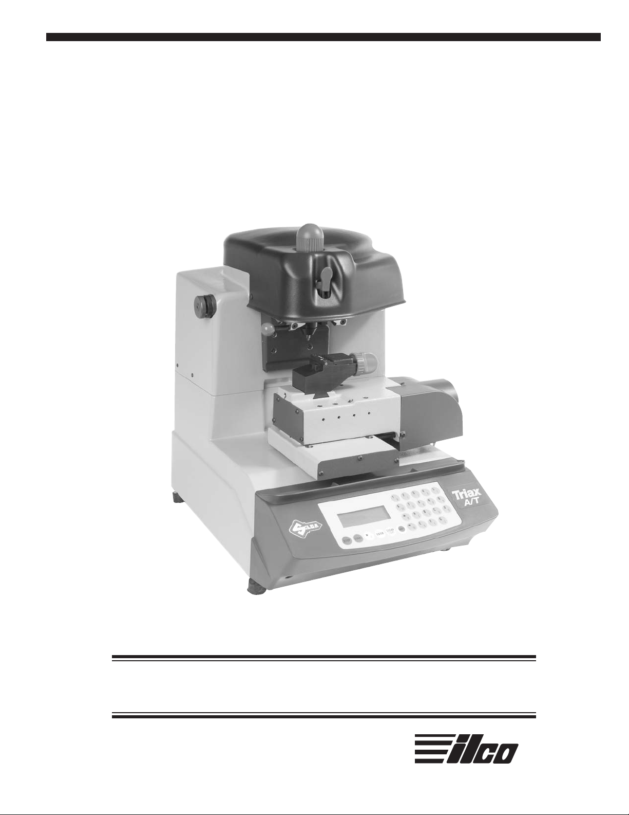
Triax A/T Quick Start Guide
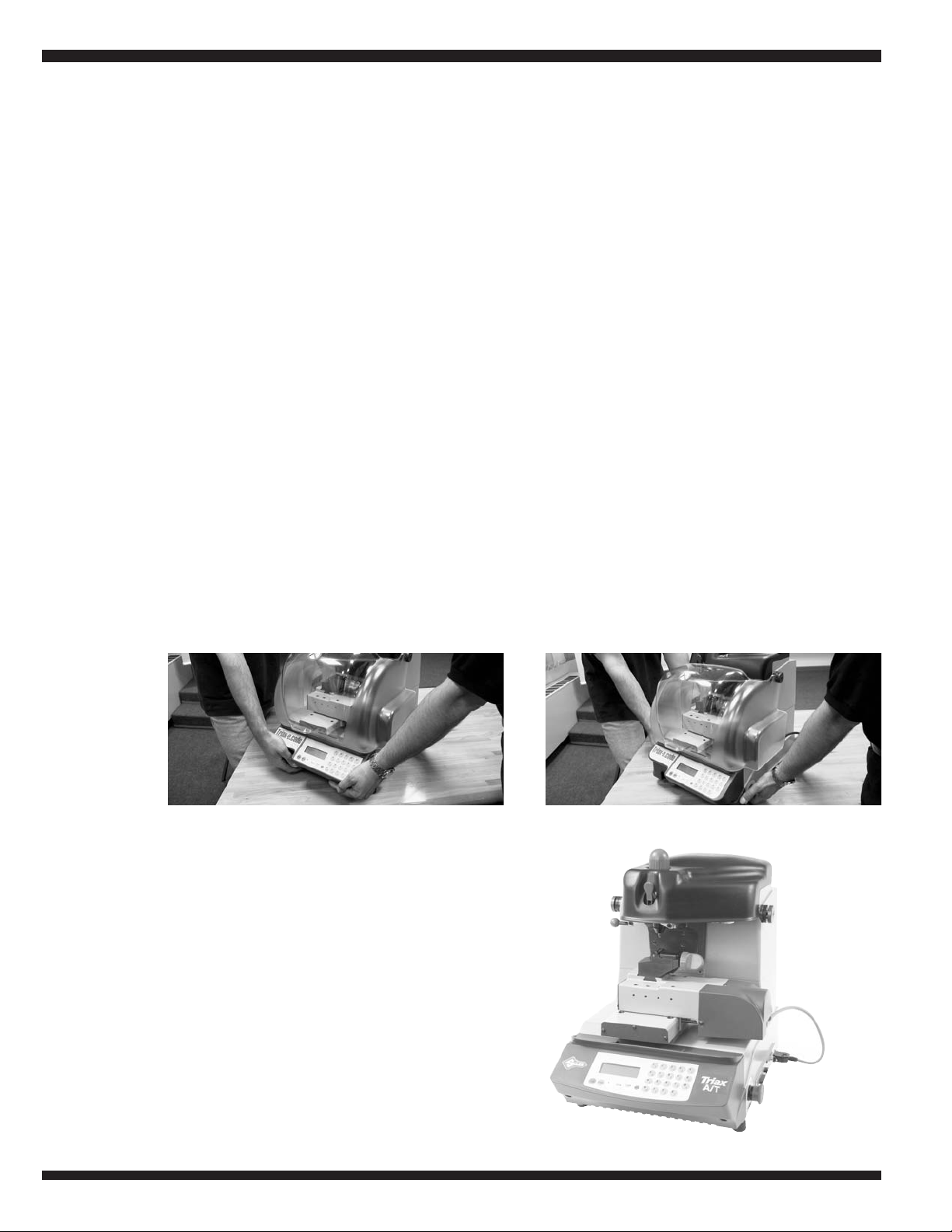
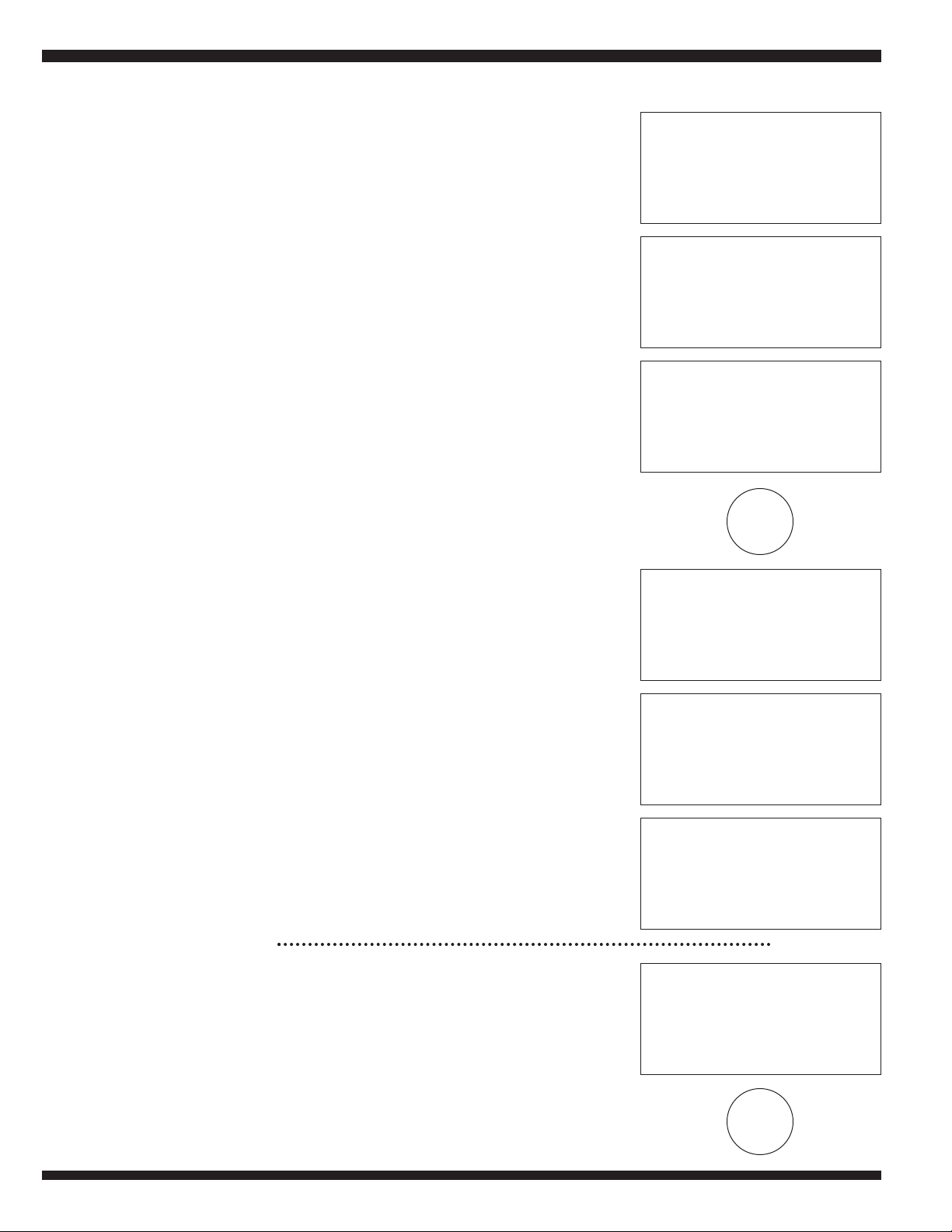
C. Place the machine on a horizontal surface,
solid enough to support the weight of
93 lbs (45kg). The dimensions of the
Triax A/T are 17” (43.2 cm)L X 20”
(50.8 cm)W X 20” (50.8 cm)H. It is strong-
ly suggested to have 12-inch clearance
around the top and back of the machine
and a 24-inch clearance on the bottom right
side of the machine. This will allow easy
access to the serial port; Y-axis connection
port and the emergency stop button.
Ensure that the main power supply is the
same as the machine, 110V/AC. This sup-
ply should be properly grounded and the
machine connected to a surge protected
power strip.
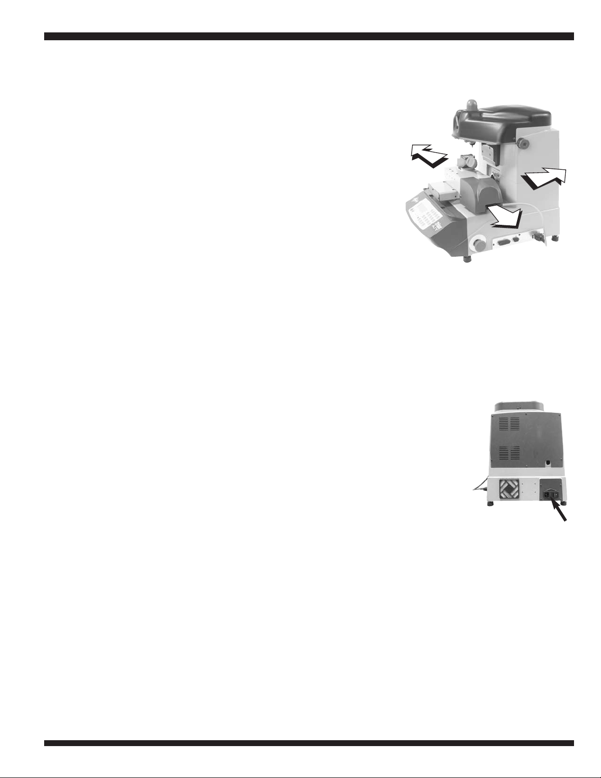
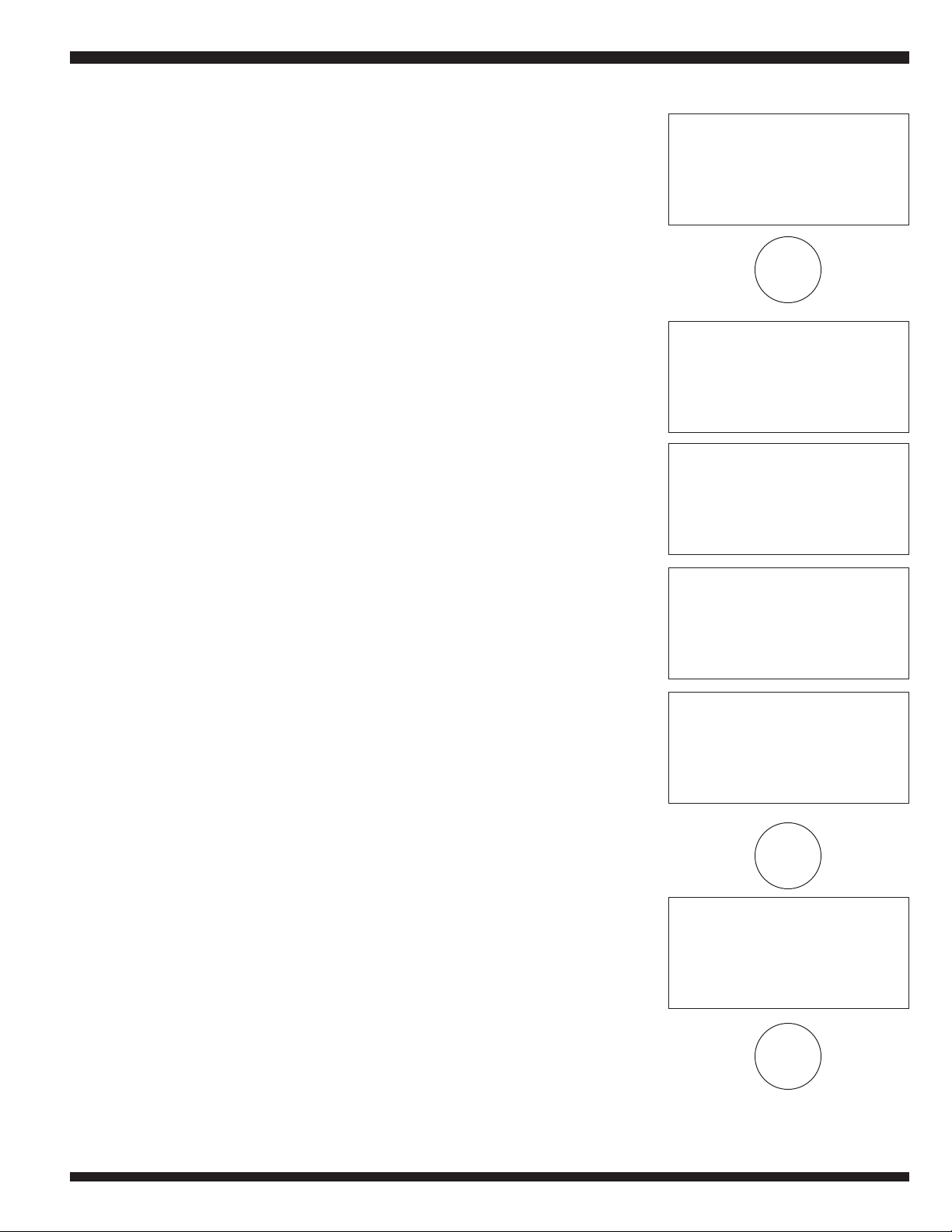
D. VERY IMPORTANT: The serial cable on the right hand side of the machine
must be plugged into the uncovered serial (Y) port, also located on the right
hand side of the machine. This allows the X, Y and Z-axis to function prop-
erly.NOTE:It is essential the Yaxis cable be plugged into its designated serial
port BEFORE the machine’spower switches are activated. If this is not done,
the machine’smotherboard could be damaged resulting in expensive repairs
and down time.
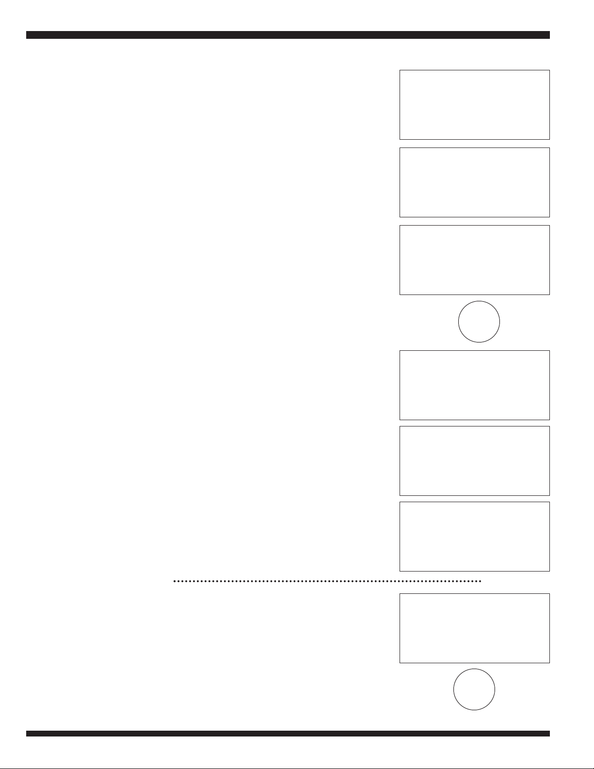
E. Attach the power cord to the Triax A/T and plug it into
an 110V/AC circuit. The on/offmain rocker switch is
located on the back left hand side of the machine.
Make sure that the red emergency stop button, locat-
ed on the right hand side of the machine, is disen-
gaged. To make sure that the emergency stop button
is disengaged, push the button in towards the
machine to activate it and then rotate the
button 45° clockwise, to deactivate it. The button
should “pop” out away from the machine.
F. Turn the Triax A/T machine ON.
G. Push the SHIFT and STOP buttons simultaneously to bring the carriage to
the starting position. Once the carriage has come to a complete stop, the
operator may remove the styrofoam behind the X and Y-axis, then proceed
with setting up the Triax A/T machine.
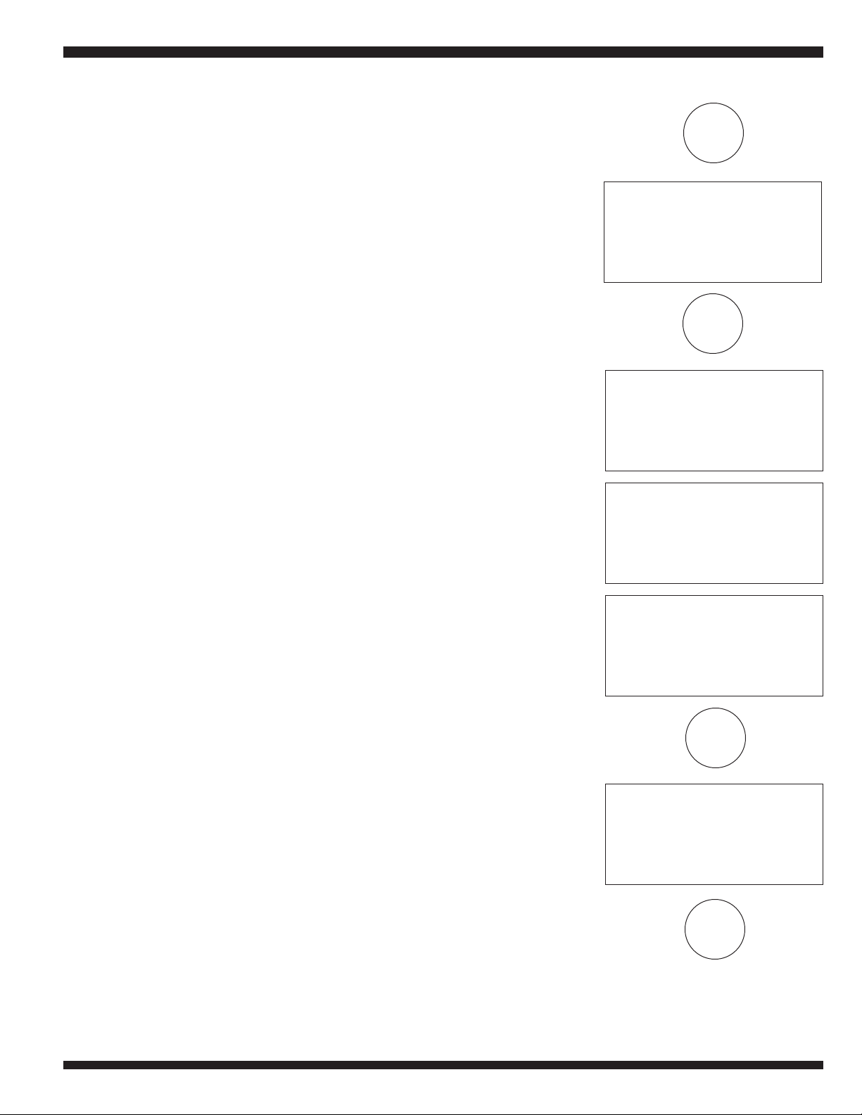
2. Initial Operations
A. When the machine has been turned on, the display will show the machine
model and the internal software version for a few seconds. This version
should be 036 or higher. If not, please contact Ilco Technical Assistance.
power supply