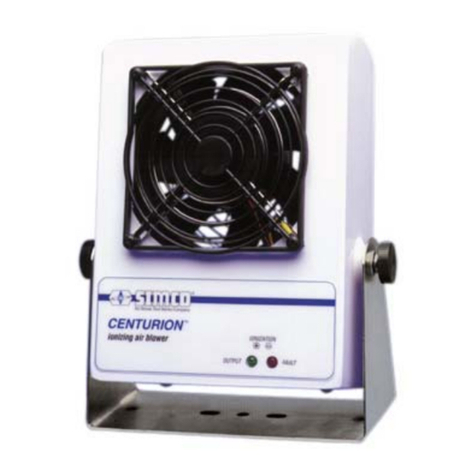
Illinois Tool Works Simco Aerostat XC Instruction Manual

INSTRUCTIONS
Operation/Maintenance
Aerostat XC™ Ionizing Air Blower
2257 North Penn Road
Hatfield, PA 19440
(215) 997-0590
(800) 538-0750
Fax: (215) 997-3450
Publication 5100550 rev F
February, 2002
SIMCO’s Aerostat XC was designed for use with sensitive electronic components where
electrostatic discharge (ESD) is a problem. It can be applied in inspection, testing, and
assembly environments. The Aerostat XC can also be used where static electricity causes
problems such as attraction of dirt to product, misalignment of small parts due to electrostatic
"jumping", and undesirable adhesion of plastic films due to electrostatic charge.
SECTION 1 Description
SECTION 2 Features
SECTION 3 Specifications
SECTION 4 Safety
SECTION 5 Installation
SECTION 6 Operation
SECTION 7 Maintenance
SECTION 8 Replacement Parts
SECTION 9 Warranty

SECTION 1 Description
The Aerostat XC ionized air blower produces an air flow that is rich in positive and
negative ions. Directing the air flow on an object that has a static charge will neutralize
the charge. If the object has a positive static charge, it will draw negative ions from the
air flow. If the object has a negative static charge, it will draw positive ions from the air
flow. The ions are attracted to the oppositely charged object and neutralize the
electrostatic charge on the object.
The Aerostat XC uses a three-speed tangential blower to produce a uniform air flow.
This air flow is directed into a duct, which shapes the airflow. The duct also contains a
heater and ionizer. The low-wattage heater can be turned on at any time for user
comfort. The ionizer uses a transformer which produces high voltage AC. This unit is
current limited for safety. The transformer output also contains a current limiting resistor
which provides redundant safety and enhances the ionization stability. The AC is
applied to a row of stainless steel ion emitters, which results in an intense alternating
electric field at the tip of the emitters. It is this intense electric field that introduces
alternating polarity ions into the air flow. The shaped air flow exiting the Aerostat XC
carries these ions over a broad area for control of electrostatic charge. To ensure that
the unit is working properly, the output is monitored by an ionization indicator lamp.
The ionizer of the Aerostat XC features an exclusive balancing circuit which works by
isolating the transformer secondary from electrical ground. This results in the equal
production of positive and negative ions. The Aerostat XC also features a patented built-
in emitter cleaner. Taking a few seconds to clean the emitters on a weekly basis
prevents the build-up of airborne debris, keeping your Aerostat XC working in top form
for the life of the unit.
SECTION 2 Features
• Rapidly neutralizes static charges
• Covers an extended area with ionized air
• Three-speed fan with wide range of air flow
• Low-wattage heater for operator comfort
• Bench stand or optional pedestal mount with 360' adjustability
• Inherently balanced ion output
• Built-in ion emitter cleaner
• Ionization indicator lamp
• Durable, electrically grounded steel enclosure
2

SECTION 3 Specifications
Unit Part Number: 4002612 4002667
Line Voltage: 120 VAC, 60 Hz. 220-230 VAC, 50 Hz
Current Draw: Max. 3.6 Amp* 1.8 Amp*
Min. 0.6 Amp 0.3 Amp
*Heater on
Air Volume Output: Fan Speed Flow
Low 70 CFM
Medium 95 CFM
High 102 CFM
Air Velocity Fan Speed 1 ft. 2 ft. 3 ft. 4 ft.
Low 600 300 180 150
Medium 800 400 220 180
High 1000 500 250 200
Velocity in FPM measured at center line of air stream
Air Flow Characteristics: 3’ x 6’ Area Coverage
Heated Air Temperature: Fan Speed Above Ambient
(where applicable) Low 11°F (6°C)
Medium 9°(5°C)
High 7°F (4°C)
Measured 6” in front of unit.
Operating Temperature: 32°F (0°C) -- 122°F (50°C)
Ozone Production: 0.005 ppm measured 6” in front of unit
Test conducted in accordance with EPA EQOA-0577-
019 using Dasibi Ozone Monitor model 1003AH
Audible Noise: Fan Speed
Low 52 dB
Medium 58 dB
High 64 dB
measured 2 ft. from unit.
Enclosure: Steel
Finish: White Acrylic Enamel
Weight: 17.5 lbs (7.9 kg)
Size: 15-3/8” W x 4-1/2” H x 8-1/8” D
3

(39.1 cm W x 11.4 cm H x 20.6 cm D)
Bench Stand Feet: Nonconductive, Nonstaining Polymer
Optional Air Filter: 30 PPI Open Cell Polyurethane Foam
Ion Balance (offset voltage): 0V + 5
Ion Output (discharge time):
Fan Speed - High 1 ft. 2 ft. 3 ft. 4 ft.
5 5.5 6.5 8.5 12 inches
1.5 2.5 4 5.5 Center Line
5 5.5 6.5 8.5 12 inches
Fan Speed - Medium 1 ft. 2 ft. 3 ft. 4 ft.
6 7 9 11 12 inches
1.7 3.5 5 7 Center Line
6 7 9 11 12 inches
Fan Speed - Low 1 ft. 2 ft. 3 ft. 4 ft.
8 9 10 12 12 inches
2 5 7 9 Center Line
8 9 10 12 12 inches
Offset voltage and discharge time determined as per ESD Association Standard No. 3
using 6” x 6”, 20 pF plate (charge plate monitor). Discharge times are in seconds from
1000 volts to 100 volts.
Note: Discharge times for high speed are 10% longer for 230 V, 50 Hz.
SECTION 4 Safety
4.1 Read all instructions before proceeding with installation or operation. Failure to
follow instructions may result in damage to the ionizer and/or personal injury.
4.2 This unit is supplied with a 3-prong grounding plug, which must be inserted in an
appropriate, properly wired, and grounded receptacle. Do not defeat the electrical
ground, grounding and proper wiring are required for proper operation.
4.3 Keep the unit dry. Do not operate the ionizer in a flammable, volatile or explosive
atmosphere.
4.4 Do not insert objects through the unit’s intake or outlet grilles. Damage to the
ionizer and/or personal injury may result.
4.5 Do not ground or make electrical connections of any kind to the unit’s metal fan
guards located on the intake and output.
4

4.6 A factory-qualified service technician must perform component service and repairs.
Please contact SIMCO Customer Service for information.
SECTION 5 Installation
Carefully remove the equipment from the carton and inspect contents. Empty the carton
to insure that small parts are not discarded. If any damage has occurred during
shipment, notify the local carrier at once. A report should also be forwarded SIMCO,
2257 North Penn Road, Hatfield PA 19440, Phone (215) 822-2171. See Section 9 for
Return Shipment information.
The Aerostat XC is designed for portable or permanent operation. It is supplied with a
bench stand; an optional pedestal mount (part number 5050282) is available. The
bench stand can be used for portable operation or bolted to a sturdy flat surface such as
a wall or under a shelf. If the bench stand is bolted in place, use 5/16-inch diameter
screws or bolts to secure it.
For extremely dirty environments, an optional air filter kit (part number 5050281) is
available. The air filter kit contains user-installed brackets and an air filter that can be
cleaned and reused.
The Aerostat XC should be placed approximately 1 to 3 feet from the critical work area
or objects to be neutralized. It should be positioned to cover as much of the area as
possible with the ionized air stream. The air stream can be directed upward or
downward by tilting the unit on the stand. Tightening the lock knobs on each side of the
unit secure it in position.
The Aerostat XC, part number 4002612, requires 120 VAC 60 Hz for proper operation.
The unit must be grounded for safe operation. Plug the unit into a standard 3-terminal
grounded receptacle.
The Aerostat XC, part number 4002667, requires 220-230 VAC 50 Hz. for proper
operation. The unit must be grounded for safe operation. The unit comes with line cord,
without plug. A plug must be installed on the line cord for operation. Installation of the
plug must be performed by qualified service personnel. The color code for wiring the
plug is as follows: Brown - Line; Blue - Neutral; Green/Yellow - Ground.
5

SECTION 6 Operation
Activate the XC by setting the POWER switch to the ON position. The ionization
indicator will illuminate to indicate the presence of ionized air. Set the air flow as desired
by adjusting the FAN SPEED to low ( I ), medium ( I I ), or high ( I I I ). If warm air is
desired for operator comfort, set the HEATER switch to the ON (I) position. The
direction of the air stream can be adjusted upward or downward by loosening the
lock knobs, tilting the unit and retightening the knobs.
The Aerostat XC produces an ionized air stream that covers a large area uniformly.
The time required to neutralize a static charge on an item in this area depends on many
factors. Two important factors are: distance to the ionizer and air velocity. Air ions
constantly "neutralize" each other. Positive and negative ions are electrostatically
attracted to each other. When they contact, the charge transfers and the ions
recombine. With high air velocity, the ions travel further before they recombine. Setting
the fan speed to high results in coverage for the greatest possible area. Decreasing the
distance to the ionizer results in more rapid neutralization. For fast neutralizing, the item
should be held within 1 to 3 feet from the Aerostat XC. For virtually instantaneous
neutralizing, the item may be held as close as 6 inches.
When using the Aerostat XC in an electronics assembly area, the ionized air stream
should cover as much of the work area as possible. The constant flow of ionized air will
prevent items such as work surfaces, tools, materials and components from developing
a static charge. Charged items introduced into the work area will be neutralized and will
remain neutral while they are in the air stream.
6

SECTION 7 Maintenance
The Aerostat XC has been designed with low maintenance in mind. The only regular
maintenance suggested is emitter point cleaning, ion balance checking and ion output
checking. Emitter point cleaning takes only seconds with SIMCO’s patented point
cleaner. The Aerostat XC contains a patented balancing circuit that is inherently self
balancing. This circuit compensates for dirt build-up on emitters, emitter point wear, line
voltage fluctuations and variations in air velocity. Scheduled checking of the ion output
and balance should be considered to assure quality audit requirements.
CAUTION! ELECTRICAL SHOCK HAZARD!
Do not insert objects through intake or outlet grille.
7.1 Emitter Cleaning
To clean the ion emitters, simply sweep the emitter cleaner back and forth once across
the ionized air outlet. Recommended frequency of cleaning is once a week.
7.2 Air Inlet and Outlet Cleaning
The air inlet grille on the rear of the unit and the ionized air outlet should remain clean to
prevent restriction of air flow. They can be cleaned with a soft brush or vacuum.
7.3 Optional Air Filter Cleaning
Remove the air filter from the rear of the unit by sliding the aluminum frame of the filter
towards the rear of the unit. Rinse the filter in plain water while gently squeezing. If the
dirt is stubborn, wash the filter in mild soap and water then rinse. Blot the filter dry with
paper towels and allow to dry. Reinstall filter on air inlet by sliding it under brackets
from rear of the unit. IMPORTANT: If an air filter is used, clean the air filter regularly.
7.4 Ion Output Check
To test the unit for ion output, the use of a charge plate monitor such as the SIMCO
EA-4 is recommended. Discharge times can be measured and checked against the Ion
Output tables in Section 3, Specifications. If a charge plate monitor is not available, but
a static meter such as a SIMCO handheld electrostatic fieldmeter is available, ion output
may be checked with the following procedure. Take a piece of plastic and rub it with
cloth until a static charge can be read with the static meter. Turn on the Aerostat XC.
Hold the plastic one foot away from the ionized air outlet for five seconds. Remove the
plastic from the ionized air stream and measure the static charge. The plastic should be
neutralized.
If no instrumentation is available, the XC’s operation can be verified with the following
procedure. Tear off about a 10-inch length of Scotch® brand (or equivalent) transparent
tape. Approach the non-adhesive side of the tape with your free hand and note the
electrostatic attraction of the tape to your hand. Pass the tape through the ionized air
stream approximately 1 foot from the unit and again approach the non-adhesive side of
the tape with your free hand. If the tape has been neutralized, it will not attract.
7

Do not try to verify operation of the unit by drawing a spark from an ion emitter point.
The design of the balancing circuit makes the “spark test” inconclusive. Sustained
grounding of the ion emitters may damage the balancing circuit.
7.5 Ion Balance Check
To test the unit for ion balance, the use of a charge plate monitor such as the SIMCO
EA-4 is recommended. Offset voltage should be measured and checked against the
Ion Balance in Section 3, Specifications.
Do not try to determine ion balance by holding a static meter in the ionized air stream.
This will result in a meaningless reading.
7.6 Calibration
The Aerostat XC’s ion output is inherently balanced by design, so there are no
calibration adjustments. If, after checking the ion balance as outlined above, an
unbalance or offset voltage exists in excess of 0+ 5 volts, contact SIMCO Customer
Service at 800-538-0750.
Never open the case of the unit. This exposes hazardous voltages. If repairs are
necessary, call SIMCO for a Return Authorization Number and return the unit to the
factory.
8

SECTION 8 Replacement Parts
Item Part Number Description
1 4750557 Chassis
2 4340350 Lid
3 5050284 3-Speed Blower, 120 V
3 5050294 3-Speed Blower, 230 V
4 4630136 HV Transformer with Leads, 120 V
4 4630141 HV ransformer with Leads, 230 V
5 4103939 Ionizer Duct Assembly, 120 V
Duct Assembly includes:
5 4104036 Ionizer Duct Assembly, 230 V heater, ionizer, and brush
6 4670700 Brush
7 4401510 Ionizer Duct Standoff (2 required)
8 4103940 Line Cord Assembly, 120 V
8 4104035 Line Cord Assembly, 230 V
9 4610699 Illuminated Rocker Switch, 120 V
9 4610729 Illuminated Rocker Switch, 230 V
10 4610700 3-Position Rotary Switch and Knob
11 4670702 Lock Knob (2 required)
12 4103942 Bench Stand
13* 5050282 Pedestal Mount (includes hardware)
14* 5050281 Air Filter Kit (includes filter, mounting brackets and hardware)
15* 4470059 Air Filter
16 4104354 Ionizer indicator assembly
* Optional Equipment
9

SECTION 9 Warranty
SIMCO warrants its products to be free of defects in components, workmanship, or
materials for a period of one year from date of purchase. This warranty does not apply
to any physical or electrical damage caused by misuse, abuse or negligence (such as
any modifications made to the unit or service work done by any other than SIMCO
authorized technicians). Any unit with altered or removed serial number is ineligible for
warranty.
SIMCO will not be liable for loss or damage due directly or indirectly to an occurrence
or use for which the product is not designed or intended. In no event shall SIMCO be
liable for incidental or consequential damages except where state laws override.
This warranty extends to the original purchaser and is not transferable. No person,
agent, distributor, dealer or company is authorized to change, modify, or amend the
terms of this warranty in any manner whatsoever.
All products returned must have an “RA” (Return Authorization) number regardless of
warranty status. Call SIMCO for an assigned RA number.
Information in this document is subject to change without notice and does not represent
a commitment on the part of SIMCO. No part of this manual may be reproduced or
transmitted in any form or by any means, electronic or mechanical, including
photocopying and recording, for any purpose other than the purchaser’s personal use
without written permission of SIMCO.
2257 North Penn Road
Hatfield, PA 19440
Phone: (215) 997-0590
(800) 538-0750
Fax: (215) 997-3450
http://www.simco-static.com
10
This manual suits for next models
2
Table of contents
Other Illinois Tool Works Air Ionizer manuals
Popular Air Ionizer manuals by other brands
EAAZPOOL
EAAZPOOL SOLAR IONIZER manual
Terra Universal
Terra Universal IonBar Installation and operating guide

ITW
ITW Simco-Ion IQ Power Fantom Installation and operating instructions
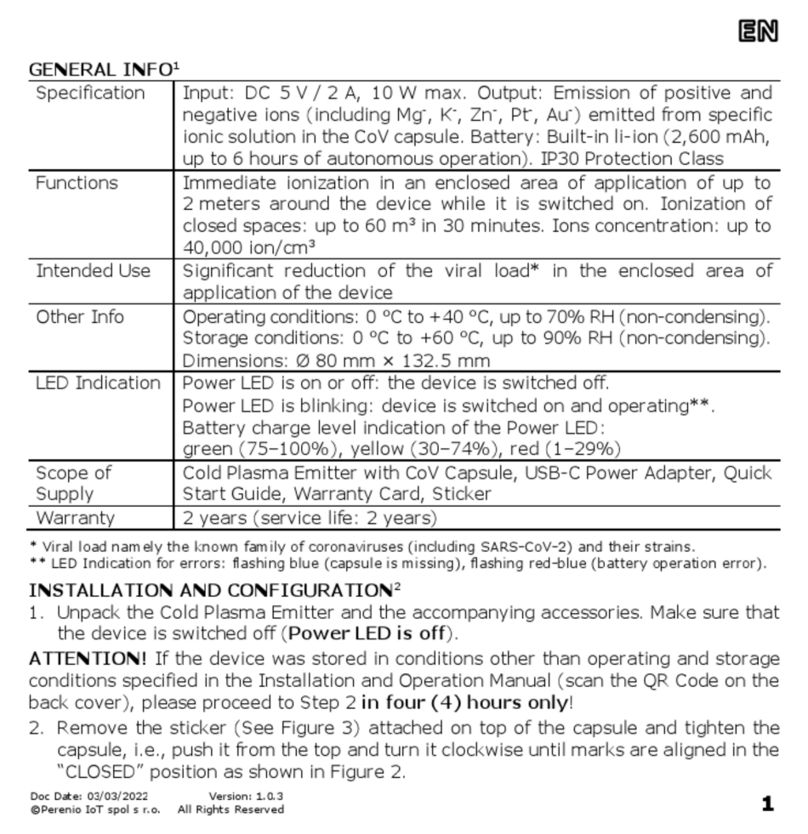
Perenio
Perenio IONIC SHIELD PEWOW01COVUK instructions

Meech
Meech 200 Series operating manual

Klarstein
Klarstein ST.-OBERHOLZ instruction manual
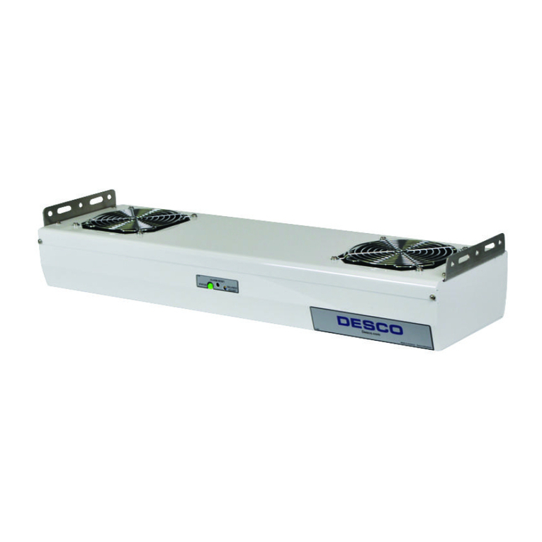
Desco
Desco Chargebuster 60640 Installation, operation and maintenance

Panasonic
Panasonic ER-F Series instruction manual
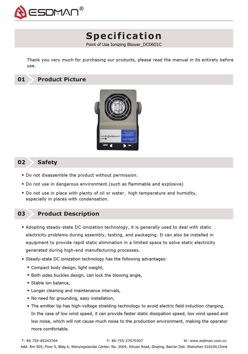
ESDMAN
ESDMAN DC0601C specification
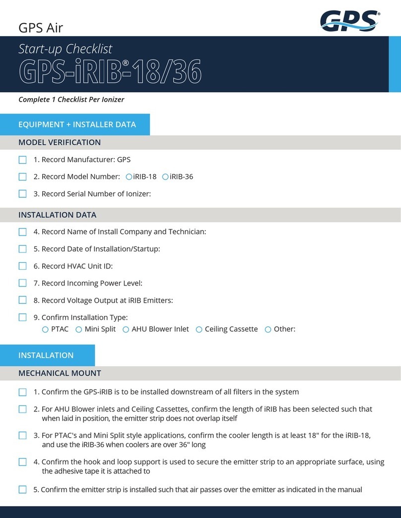
GPS
GPS iRIB-18 Start-Up Checklist

Desco
Desco 19500 Installation, operation and maintenance
Simco-Ion
Simco-Ion Ioncell Installation and operating instructions
