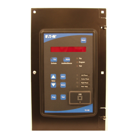
Eaton TC-100 User manual

Instruction Leaflet IL02602014E – Rev. B
The purpose of this quick start guide is guide the user through the essential steps required to
commission an Eaton Transformer Temperature Controller. This quick start guide is not a
replacement for the complete manual which can be found on the CD shipped with your TC-100,
TC-50M, or TC-50. For wiring instructions and complete descriptions of the functions, please
consult the complete instruction manual.
Transformer Temperature Controllers
Quick Start Guide
Contents
Description Page
Section 1 Device Installation 1
Section 2 Front Panel Interface
Overview 2
Section 3 PC Application
Installation and
Overview
3

Instruction Leaflet IL02602014E – Rev. B
ii Transformer Temperature Controllers Quick Start Guide IL02602014E – Rev. B March 2012 www.eaton.com
Copyright © 2012 by Eaton Corporation. All rights reserved.
Specifications and information contained herein are subject to change without notice.
EATON CORPORATION - CONFIDENTIAL AND PROPRIETARY NOTICE TO PERSONS RECEIVING THIS DOCUMENT
AND/OR TECHNICAL INFORMATION
THIS DOCUMENT, INCLUDING THE DRAWING AND INFORMATION CONTAINED THEREON, IS CONFIDENTIAL AND
IS THE EXCLUSIVE PROPERTY OF EATON CORPORATION, AND IS MERELY ON LOAN AND SUBJECT TO RECALL
BY EATON AT ANY TIME. BY TAKING POSSESSION OF THIS DOCUMENT, THE RECIPIENT ACKNOWLEDGES AND
AGREES THAT THIS DOCUMENT CANNOT BE USED IN ANY MANNER ADVERSE TO THE INTERESTS OF EATON,
AND THAT NO PORTION OF THIS DOCUMENT MAY BE COPIED OR OTHERWISE REPRODUCED WITHOUT THE
PRIOR WRITTEN CONSENT OF EATON. IN THE CASE OF CONFLICTING CONTRACTUAL PROVISIONS, THIS
NOTICE SHALL GOVERN THE STATUS OF THIS DOCUMENT.
DISCLAIMER OF WARRANTIES AND LIMITATION OF LIABILITY
The information, recommendations, descriptions and safety notations in this document are based on Eaton Electrical Inc.
and/or Eaton Corporation’s (“Eaton”) experience and judgment and may not cover all contingencies. If further information is
required, an Eaton sales office should be consulted.
Sale of the product shown in this literature is subject to the terms and conditions outlined in appropriate Eaton selling policies
or other contractual agreement between Eaton and the purchaser.
THERE ARE NO UNDERSTANDINGS, AGREEMENTS, WARRANTIES, EXPRESSED OR IMPLIED, INCLUDING
WARRANTIES OF FITNESS FOR A PARTICULAR PURPOSE OR MERCHANTABILITY, OTHER THAN THOSE
SPECIFICALLY SET OUT IN ANY EXISTING CONTRACT BETWEEN THE PARTIES. ANY SUCH CONTRACT STATES
THE ENTIRE OBLIGATION OF EATON. THE CONTENTS OF THIS DOCUMENT SHALL NOT BECOME PART OF OR
MODIFY ANY CONTRACT BETWEEN THE PARTIES. In no event will Eaton be responsible to the purchaser or user in
contract, in tort (including negligence), strict liability or otherwise for any special, indirect, incidental or consequential damage
or loss whatsoever, including but not limited to damage or loss of use of equipment, plant or power system, cost of capital,
loss of power, additional expenses in the use of existing power facilities, or claims against the purchaser or user by its
customers resulting from the use of the information, recommendations and descriptions contained herein.

Instruction Leaflet IL02602014E – Rev. B
Transformer Temperature Controllers Quick Start Guide IL02602014E – Rev. B March 2012 www.eaton.com
1
Section 1, Device Installation
1.1 Mechanical Mounting
Cut/drill the appropriate mounting holes and securely install the barrier cabinet in the transformer enclosure.
1.2 Thermocouple Wiring
Connect the thermocouple leads from the transformer windings to connector J2. Install the ambient
thermocouple in the desired location and connect its leads to connector J2.
1.3 Remote
Interface Wiring
Connect leads to the
RS-485 Modbus
interface connector
J8, the 4-20 mA
interface connector
J7, the Alarm and
Trip relay outputs on
connector J1, and
the discrete inputs on
connector J1 as
desired.
1.4 Fan
Power/Control
Wiring
Connect the fan input
power and wiring to
the fans to
connectors J9 and
J10.
1.5 Control
Power Wiring
Connect the control
power wiring to
connector J1
1.6 Wiring Review
Ensure all control power and fan power wiring is sized and fused properly. Ensure all signal and control wiring
is properly segregated from power wiring within the transformer cabinet. Ensure all wiring within the barrier
cabinet is secured to avoid excessive strain when the front cover is closed.
1.5 Initial Power-up
Apply control power to the unit and verify the power-on self test completes and the unit displays proper
temperatures for the connected thermocouples.
Use the front panel Prog button or PC Application to configure any necessary parameters. At the very
least the current date/time should be verified/set. If the Modbus interface is to be used its configuration
should also be verified/set.
Use the front panel Test button to enter test mode and turn on the individual relays to verify their wiring.
Also verify that all of the buttons and LEDs operate properly and verify that the internal temperature is
correct.
2
3
4
5
6
7
8
9
10
11
12
13
Transformer
Temperature
Controller
1
2
3
4
1
J2
1
2
3
4
J8
J1 J7
J9
J10
(+) 2
(-) 1
1
2
3
4
1
2
3
4
5
6
7
8
FAN
POWER
FAN 1
FAN 2
BURDEN
<1K OHM
R
4-20mA
LOOP
Modbus
Network
T
REMOTE TRIP
REMOTE ALARM
NON CURRENT
CARRYING GROUND
CONTROL
POWER
TRIP/
ALARM
POWER
L
C
R
+
-
+
-
+
-
+
-
THERMOCOUPLES
in TRANSFORMER
WINDINGS
THERMOCOUPLE
in CABINET
AMBIENT AIR
4-20mA
OUTPUT
A
B
COMMON
Shield
THERMOCOUPLE INPUTS
RS-485 Modbus
MONITOR
(TC-50 Modus
and
TC-100 Only)

Instruction Leaflet IL02602014E – Rev. B
Transformer Temperature Controllers Quick Start Guide IL02602014E – Rev. B March 2012 www.eaton.com
2
Section 2, Front Panel Interface Overview
2.1 Reset Button
The Reset button is used to reset latched alarm/trip events and to clear the various event and parametric data
memories. It is password protected. If the password has not been changed from the default simply press the
Select button when ‘PWD****’ is displayed on the LED Display.
2.2 Fan Button/LED
When Manual Fan Control is enabled the Fan button can be used to turn the fans ON or OFF. Note that fans
cannot be manually turned OFF with the Fan button if they are ON due to winding temperature above the fan
threshold. The Fan LED is illuminated whenever the fan(s) are ON.
2.3 Alarm Button/LED
The Alarm button is used to test/silence the audible alarm when the audible alarm is enabled. When no alarm is
present the Alarm button toggles the audible alarm ON and OFF. When an alarm is present and the audible
alarm is sounding, the Alarm button silences the audible but does not affect the alarm relay state. The Alarm
LED is illuminated whenever an alarm condition is present or latched.
2.4 Trip LED
The Trip LED is illuminated whenever a trip condition is present or latched.
2.5 Program LED
The Program LED is illuminated while the unit is placed in the Program mode using the Prog button.
2.6 Test LED
The Test LED is illuminated while the unit is placed in the Test mode using the Test button.
2.7 Up/Down Arrow Buttons
The Up and Down Arrow buttons are used to scroll through the four temperature inputs in Max display mode
and to navigate through the various front panel menus.
Reset Button
LED Dis
p
la
y
Tri
p
LED
Pro
g
ram LED
Test LED
Channel LEDs
USB Interface
A
larm Button/LED
A
larm Button/LED
Back Button
Select Button
Pro
g
ram Button
Test Button
Up/Down
ArrowButtons

Instruction Leaflet IL02602014E – Rev. B
Transformer Temperature Controllers Quick Start Guide IL02602014E – Rev. B March 2012 www.eaton.com
3
2.8 Back Button
The Back Button is used to return up through the levels of the various front panel menus.
2.9 Select Button
The Select Button is used to view event and parametric data logs as well as date/time and firmware version
during normal Max/Scroll operation. It is also used to navigate through the various front panel menus.
2.10 Channel LEDs
The Channel LEDs illuminate to indicate the channel whose temperature data is being displayed. The pre-
printed label can be removed and inverted, and the back side used to customize the channel descriptions for
each particular application.
2.11 Prog Button
The Prog Button is used to enter the programming mode to configure the various monitor and control features of
the TC device. It is password protected. If the password has not been changed from the default simply press
the Select button when ‘PWD****’ is displayed.
2.12 Test Button
The Test Button is used to enter the test mode to verify proper operation of the relays, front panel interface, and
internal temperature monitor. It is password protected. If the password has not been changed from the default
simply press the Select button when ‘PWD****’ is displayed.
2.13 USB Interface
A USB interface is provided for local configuration and downloading of data using the TC Series PC application.
It is protected with a flip-up door that can be further secured with a seal wire.
Section 3, PC Application Installation and Overview
3.1 Software Installation
Insert the CD provided with your TC-100, TC-50M, or TC-50 into the PC.
If the installation does not automatically start, navigate to the CD ROM drive and run “setup.exe”.
Follow the prompts to install the application.
Next install the USB driver by navigating to the “USB_Driver” folder and running “vcp_v1.3.1_setup.exe”
for 32-bit operating systems or “vcp_v1.3.1_setup_x64.exe” for 64 bit operating systems.
If desired, copy the product manual to the PC for future reference.
After the application and USB driver are properly installed, connect the TC device to the PC with a
standard USB cable. The “Found New Hardware” dialog will open and the USB driver will be
automatically set up.
3.2 Application Startup
Once installed, start the PC application from the Start menu or the TC Series icon on the desktop. The
Offline/Connected Device indicator in the upper right corner of the PC application indicates the state of the USB
connection from the PC to a TC-100, TC-50M, or TC-50 device. The PC application will run without a TC device
connected, but any features that require communications with the device will not function.
Offline/Connected Device Indicator

Instruction Leaflet IL02602014E – Rev. B
Transformer Temperature Controllers Quick Start Guide IL02602014E – Rev. B March 2012 www.eaton.com
4
3.3 Configuration
The Configuration options allow the user to create a ‘New’ configuration, ‘Open’ an existing configuration file on
the PC, or ‘Read’ the configuration parameters from a TC device connected to the PC via USB. This
configuration can be modified as desired and then ‘Saved’ to a file on the PC, ‘Written’ to the TC device (if
connected via USB), and/or ‘Printed’ out for a hard-copy record.
3.4 Device
The Device options allow the user to download ‘Trend/Log Data’ from a TC-1001unit connected to the PC via
USB. It provides the option to ‘Upgrade Firmware’ in any TC device connected to the PC via USB. Caution -
This feature should only be used following procedures outlined with a firmware upgrade package
provided by Eaton. It enables the user to change the password used to access the front panel Reset,
Program, and Test functions. Finally it provides the option to field-upgrade a TC-50 or TC-50M to a higher
featured device.
3.5 Reports (TC-100 Only)
The Reports options provide the user with graphs and tabular reporting of parametric (‘Trend’ and ‘Fan Wear
Indicator’) and event (‘Trip Log and Alarm Log’) data that was previously downloaded from one or more TC-1001
units via the USB interface. The reports can be viewed on screen, exported for use by other applications, or
printed for a hard-copy presentation.
3.6 Calibration
The Calibration feature is used only by trained Eaton personnel during manufacturing or field service. It is
password protected from the normal user. Any attempt to calibrate the unit by other than an Eaton authorized
employee may adversely affect operation of the TC device and will void the product warrantee.
3.7 Help
The Help feature provides and overview of the various features of the TC Series PC application.
3.8 Exit
The Exit button is a convenient means of exiting the TC Series PC application. The standard Windows close
button in the upper right corner can also be used.
1Trend/Log data is not available from TC-50 or TC-50M devices.
Contact Information
PQTSC: 1-800-809-2772
Email: [email protected]
Internet: http://www.Eaton.com
Eaton Corporation
1000 Cherrington Parkway
Moon Township, PA 15108-4312
USA
www.Eaton.com
© 2012 Eaton Corporation
A
ll Rights Reserved
IL02602014E Rev. B
66A2457H02
Table of contents
Other Eaton Temperature Controllers manuals