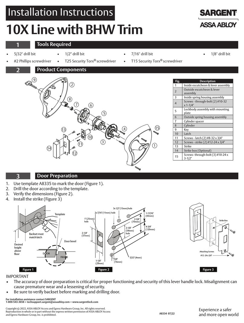
iLoq D5S.(A).SB Series Installation guide

Page 1 of 16
D5S.XXX(A).SB
D5S.XXX(L).SB
EUROPROFILE LOCK CYLINDER
MOUNTING AND CARE INSTRUCTIONS
USER GUIDE

Page 2 of 16
TABLE OF CONTENTS
1.
BEFORE INSTALLING ................................................................... 3
2.
AFTER INSTALLATION .................................................................. 4
3.
CARE .............................................................................................. 4
4.
INSTALLATION OF ILOQ D5S.1XX SERIES ................................. 4
5.
INSTALLATION OF ILOQ D5S.2XX SERIES ................................. 5
6.
INSTALLATION OF ILOQ D5S.3XX SERIES ................................. 8
7.
INSTALLATION OF ILOQ D5S.4XX SERIES ................................. 9
8.
INSTALLATION OF ILOQ D5S.7XX SERIES ............................... 10
9.
REMOVING AND INSTALLING THE O TSIDE KNOB ................ 11
10.
CYLINDER EXTENSIONS ............................................................ 13
10.1
One side .................................................................................................13
10.2
Both sides ...............................................................................................15
10.3
Long neck ...............................................................................................15
11.
GENERAL NOTES ........................................................................ 16

Page 3 of 16
1. BEFORE INSTALLING
1. These instructions should be carefully followed during installation. These instructions and any
maintenance instructions should be assed on by the installer to the user.
2. iLOQ D5S cylinders must be installed and used carefully without excessive force.
3. The roduct should not be modified in any way exce t in accordance with the modifications
described in these instructions.
4. Where the D5S cylinder is manufactured in more than one size it is critical that the correct size is
selected.
5. Care should be taken to ensure that any seals or weather-stri ing fitted to the com lete door
assembly, does not inhibit the correct o erations of D5S cylinder.
6. Care should be taken to ensure that no rojection of the D5S cylinder and associated arts, can
revent the door swinging freely.
7. All com onents necessary for the s ecific installation should be fitted in order to ensure com liance
with EN 15684 standard.
8. The cylinder must roject less than 1 mm on outside of the door to ensure ro er o eration.
9. No liability is acce ted for damage to the doors or com onents due to incorrect installation.
10. Before fitting D5S cylinder to a fire/smoke resisting door, the fire certification should be examined,
to ensure conformity.
11. To extend the cylinder length use only the associated D5 cylinder extensions (AD5.Exx).
12. It is not allowed to uninstall res . demount the anti- anic mechanism because due to that the
mechanism and functionality of the anic functionality can not be guaranteed anymore.
13. In the case the anic mechanism of the anic mortise locks can be blocked or influenced in a
negative way by the cylinder cam, it is mandatory to install the anic cylinder (D5S.7xx). The use of
the other cylinder ty es (D5S.1xx/2xx/3xxx/4xx/5xx etc.) are only allowed if the lock do not need a
s ecific cam osition res . the cam could not block the anic functionality. Please double-check the
letter of conformity of the mortise lock manufacturers.
14. When used in combination with anic locks, it is essential to ensure after installation that all arts
of the lock are in an o erational condition and that the anic function of the mortise lock is guaranteed.
15. The long neck versions are s ecially develo ed for doors where the Euro- rofile cut out is not
existing inside the door frame and only a round hole is ossible to find.
16. To meet the German VdS (VdS Schadenverhütung GmbH) requirements class CZ+ on burglary
threatened doors use D5S.XX0A.SB high security cylinder installed with a VdS a roved security lock
furniture of class B or C.
17. The cylinders may only be used for the ur ose of o ening and locking doors; other use is not
ermitted.
18. We reserve the right to make modifications or further technical develo ments without further
notice.
19. If there are any deviations from the contents in foreign language versions of the documentation,
the English original shall a ly in case of doubt.

Page 4 of 16
2. AFTER INSTALLATION
Test the cylinder functionality after installation to ensure that it does not revent the lock case from
working ro erly.
3. CARE
After 5-10,000 usages, clean contact rolls lightly with lint-free cotton ad. S ray small amount of high-
quality lock oil i.e. CRC lock oil (with PTFE) onto contact rolls.
In the case the cylinder is not working in an a ro riate way anymore, we recommend cleaning the
cylinder with e.g. com ressed air s ray or similar.
4. INSTALLATION OF ILOQ D5S.1XX SERIES
A. Ensure the cam is ointing downwards and slide lock cylinder through the lock case.
B. Fix cylinder into lock case by iLOQ fixing screw (A10.64, art of the delivery), use tightening
torque 0.9 ...1.1 Nm. If necessary, cut the screw to the correct length.
(calculation screw length: L = backset + 10 mm).
The screw has cutting grooves to make the cutting easier.
C. Make sure the cylinder frame is a maximum of 1.0 mm from the door leaf or escutcheon.
B.
A.
C.

Page 5 of 16
5. INSTALLATION OF ILOQ D5S.2XX SERIES
A. Remove knob from the other side of the cylinder as described in cha ter 9.

Page 6 of 16
B. Removing and installing the Outside
knob
.
C. Ensure the cam is ointing downwards and slide lock cylinder through the lock case.
D. Fix cylinder into lock case by iLOQ fixing screw (A10.64, art of the delivery), use tightening
torque 0.9 … 1.1 Nm. If necessary, cut the screw to the correct length (calculation screw
length: L = backset + 10 mm).
The screw has cutting grooves to make the cutting easier.
E. Install the ower knob as described in cha ter 9.

Page 7 of 16
F. Removing and installing the Outside
knob
.
G. Make sure the cylinder frame is a maximum of 1.0 mm from the door leaf or escutcheon
D.
C.
B.
E.

Page 8 of 16
6. INSTALLATION OF ILOQ D5S.3XX SERIES
A. Loosen screw from thumb turn with 2 mm Allen key, turn them counterclockwise, that it is
ossible to remove the knob (but do not screw them out com letely).
B. Ensure the cam is ointing downwards and slide lock cylinder through the lock case.
C. Make sure the cylinder frame is a maximum of 1.0 mm from the door leaf or escutcheon.
D. Fix cylinder into lock case by iLOQ fixing screw (A10.64, art of the delivery), use tightening
torque 0.9...1.1 Nm. If necessary, cut the screw to the correct length (calculation screw length:
L = backset + 10 mm).
The screw has cutting grooves to make the cutting easier.
E. Thum turn knob in lace.
F.
Tighten screw by turning the screw clockwise. Use tightening torque 1.5 Nm.
A.
B. C.
D. E.
F.
G.

Page 9 of 16
7. INSTALLATION OF ILOQ D5S.4XX SERIES
A. Ensure the cam is ointing downwards and slide lock cylinder through the lock case.
B. Fix cylinder into lock case by iLOQ fixing screw (A10.64, art of the delivery), use tightening
torque 0.9 ...1.1 Nm. If necessary, cut the screw to the correct length (calculation screw length:
L = backset + 10 mm).
The screw have cuting grooves to make the cutting easier.
C. Make sure the cylinder frame is a maximum of 1.0 mm from the door leaf or escutcheon.
B.
A.
C.

Page 10 of 16
8. INSTALLATION OF ILOQ D5S.7XX SERIES
A. Ensure the cam is ointing downwards and slide lock cylinder through the lock case.
B. Fix cylinder into lock case by iLOQ fixing screw (A10.64, art of the delivery), use tightening
torque 0.9 ...1.1 Nm. If necessary, cut the screw to the correct length (calculation screw
length: L = backset + 10 mm).
C. Make sure the cylinder frame is a maximum of 1.0 mm from the door leaf or escutcheon.
B.
A.
C.

Page 11 of 16
9. REMOVING AND INSTALLING THE O TSIDE KNOB
In some installation locations it is necessary to remove the outside knob from the lock cylinder. Follow
these instructions to remove the knob. Re-installing with the same instructions in the o osite order.
Be careful when inserting knob not to break the connections on the cylinder. The removal of the knob
is only ossible for eo le who have access rights for the cylinder.
A. Insert a key with access into the lock cylinder. Turn the key about 15 degrees clockwise.
B. By turning the key, the blocker hatch will o en automatically at the bottom of the outside knob.
The hatch rotects the fixing screw for unauthorized access.
C. Use Torx 6 tool to o en the screw that holds cover cu , turn the Torx tool counterclockwise.
D. Remove the cover cu .
A.
B.
C.
D.

Page 12 of 16
E. Remove the side screw and carefully detach the knob with the PCB.
F. Remove the back- late screw with a Torx 6 tool (not necessary to screw them com letely out).
G. Remove the back late by rotating it counterclockwise.
E.
F.
G.

Page 13 of 16
10. CYLINDER EXTENSIONS
10.1 One side
Cylinder length is easily adjustable in 5mm increments from 30 mm (basic length) to 100 mm by
extension iece system. Extension iece can be added to both sides of the cam for the following
cylinders:
D5S.2xx Double cylinder
D5S.3xx knob cylinder
D5S.4xx Cylinder with dummy inside
Half (D5S.1xx and D5S.5xx) and anti- anic cylinders (D5S.7xx) can be extended on the knob side
only.
Do not use more than one extension on one side of the lock cylinder. It is not ossible to concatenate
multi le extension ieces
.
A. Remove the three body fixing screws, by using a screwdriver Torx 6
B. Se arate modules.
A.
B.

Page 14 of 16
C. Insert the round extension iece inside the housing extension art o osite the side with the
black sealing, so that the recess is laced next to the black O-ring. Please check if the O-ring
is not damaged otherwise use a new one (s are art kit available “A5.005”).
D.
Insert the extension iece. Fix the extension iece with the fixing screw by using a T10 Torx
tool.
E. Insert the lock unit with extension iece back to the backbone of the cylinder housing. Fix the
lock unit into the cylinder by 3 fixing screws. Tighten screws. Use tightening torque 0.55 …
0.65 Nm.
C.
E.
D.

Page 15 of 16
10.2 Both sides
Same conce t and doing than for the one-side extensions, lease see cha ter 10.1 One side.
10.3 Long neck
In the case the outside housing of long-neck version will be extended instead three only two screws
can be used to fix the backbone (see below).
In the case the long-neck version will be used in a door with the com lete DIN cut-out we recommend
to change the long-neck backbone, which is slightly shorter, against the DIN backbone (A5.009) to
im rove the ulling rotection safety of the cylinder. Or alternatively ossible to turn the existing
backbone, means outside to inside.

Page 16 of 16
11. GENERAL NOTES
1. To meet the German VdS (VdS Schadenverhütung GmbH) requirements class CZ+ on
burglary threatened doors use D5S.XX0A.SB high security cylinder installed with a VdS
a roved security lock furniture of class B or C. Such security lock furniture corres onds
to DIN 18 257 class ES 2 and ES 3.
2. To meet the Dutch SKG*** requirements use the D5S.XXXA.SB high security cylinder.
Consult iLOQ sales re resentative for correct configuration
3. Before fitting the cylinder to a fire/smoke resisting door, the fire certification should be
examined to ensure conformity. Consult iLOQ sales re resentative for correct
configuration.
4. In the case the anic mechanism of the anic mortise locks can be blocked or influenced
in a negative way by the cylinder cam, it is mandatory to install the anic cylinder
(D5S.7xx). The use of the other cylinder ty es (D5S.1xx/2xx/3xxx/4xx/5xx etc.) are only
allowed if the lock do not need a s ecific cam osition res . the cam could not block the
anic functionality. Please double-check the letter of conformity of the mortise lock
manufacturers.
5. When used in combination with anic locks, it is essential to ensure after installation that
all arts of the lock are in an o erational condition and that the anic function of the
mortise lock is guaranteed.
6. Care should be taken to ensure that any seals or weather-stri ing fitted to the com lete
door assembly, does not inhibit the correct o erations of the cylinder.
7. Care should be taken to ensure that no rojection of the cylinder and associated arts, can
revent the door swinging freely.
8. All com onents necessary for the s ecific installation should be fitted.
9. The key is to be ke t securely so that only authorized erson may have access.
10. In case of losing a key, blacklisting of the lost key shall be done with the iLOQ
Manager software and affected locks shall be re rogrammed.
11. Es ecially in industrial areas or near the sea, im urities can cause de osits in the form of
rust and attacked the material. This equi ment should be cleaned and maintained
frequently.
12. Cylinder will lock, for security reasons, itself after 10 seconds, the key can then be removed
by turning it back to the 12 o’clock osition (either clockwise or anti-clockwise).
13. In case of roblems with functionality lease check following oints:
Check, if the locking cylinder is damaged.
Check, if foreign articles are resent in keyway.
A wrongly located cylinder within the lock case due to incorrectly mounted
furniture.
A defective mortise lock.
Incorrectly mounted locking lates.
A war ed door etc.
This manual suits for next models
6
Table of contents
Other iLoq Door Lock manuals
Popular Door Lock manuals by other brands

National Cabinet Lock
National Cabinet Lock C8174 Dimensional drawing

WALA
WALA WU 1R Assembly instructions

Soyal
Soyal AR-721K quick start guide

Signature Hardware
Signature Hardware VICTORIAN installation instructions

Simplex
Simplex LP1000 quick start guide

Corporate Locksmiths
Corporate Locksmiths CL270BLFP manual