Ilsintech SWIFT KF4 User manual

SWIFT KF4 USER MANUAL
OPTICAL FIBER ARC FUSION SPLICER
Read carefully before running KF4
www.fibrecart.com

1 SAFETY INSTRUCTIONS 3
2 PRODUCT SPECIFICATIONS AND COMPONENTS 6
2.1 | PRODUCT SPECIFICATIONS 6
2.2 | PRODUCT PACKAGE 6
3 PRODUCT OUTLINE 7
3.1 | FUNCTION BUTTONS 7
3.2 | COMPONENT NAME 8
4 INSTRUCTIONS FOR USE 9
7 ERROR MESSAGES 48
7.1 | TOO DIRTY FIBER 48
7.2 | REPLACE FIBER 48
7.3 | TOO LONG FIBER 49
7.4 | FIBER OVER ANGLE 49
7.5 | LOSS LIMIT OVER 50
7.6 | FIBER THIN ERROR 50
7.7 | FIBER THICK ERROR 50
7.8 | BUBBLE ERROR 50
7.9 | CLEAVED SURFACE ERROR 50
8 SPLICING PROBLEM SOLVING 51
8.1 | WHEN LOSS IS HIGH 51
8.2 | ABNORMAL SPLICING OPERATION 51
9 PROBLEM OCCURRENCES AND QUESTIONS 52
9.1 | POWER 52
9.2 | SPLICE 52
9.3 | SLEEVE HEATER 53
9.4 | OTHERS 53
10
WARRANTY AND REPAIR RESPONSIBILITY LIMIT 54
10.1 | INFORMATION NECESSARY FOR REPAIR 54
10.2 | TRANSPORTATION 54
10.3 | REPAIR 54
TABLE OF
CONTENTS

2
4.1|
POWER SUPPLY
9
4.2|
HOW TO TURN THE POWER ON/OFF
10
4.3|
KF4 SLEEVE HEATER
10
4.4|
SPLICE PROCEDURE
11
4.5|
REMOVING THE SPLICED FIBER
12
4.6|
HEATING PROTECTION SLEEVE
12
4.7|
USE OF WORK BELT
13
5
MAINTENANCE OF SPLICE QUALITY
14
5.1| CLEANING AND INSPECTION BEFORE SPLICE
14
5.2|
REGULAR INSPECTION AND CLEANING
15
6
MENU
17
POPUP MENU
19
6.1| SPLICE
22
6.2| HEATER
26
6.3| HISTORY (SPLICE RESULT)
31
6.4| OPTION
32
6.5| CALIBRATION
35
6.6| ELECTRODES
39
6.7| SETTING
42
6.8| INFORMATION
45
1

SAFETY INSTRUCTIONS
The KF4 is designed for convenient use on indoor and outdoor work sites. Please read all instructions to
prevent accidents and malfunctions. This user guide provides the information necessary for safe operation.
!
Keep this user guide with the product at all times.
UCL SWIFT does not take any responsibility for equipment damage and personal or physical loss incurred due
to improper use or alteration.
WARNINGS
If any of the following situations occur during use, turn off the power immediately and contact your local UCL
SWIFT office or representative:
•
Smoke, abnormal smell, noise or abnormal overheating
•
A foreign substance or liquid falls into the equipment
•
The splicer is visibly damaged
Use only the power cord and connecting devices provided with or intended for the KF4. Failure to do so may
result in fire, electrical shock or injury.
Do not touch the electrodes when the power is on. High voltage and high temperatures generated from the
electrodes may result in serious shock or burn.
Connect the provided AC power cord only as directed. Ensure that there is no foreign substance on the
terminal before connecting it to the AC power socket. Improper use may result in smoke, electrical shock, fire,
equipment damage, serious injury or even death.
Use proper power voltage.
AC power for the charger is AC100-240V, 50~60 Hz.
Test the AC power before use. When the output voltage of AC power is high or abnormal frequency is
generated, the product is damaged thus serious injury or even death may result.
AC output voltage should be measured using a circuit tester before connecting the AC power cable. Regular
inspection should also be conducted.
Do not pull the AC power cord with excessive force, apply heat or transform it.
When a damaged power cord is used, it may cause fire or injury.
Use a three-plug AC power cord. Never use a two-plug power cord, cable or plug.
Do not touch the AC plug, AC power cord or splicer with wet hands. It may cause electrical shock.
Do not disassemble the AC charger, battery or KF4. Disassembly may cause fire, electrical shock or injury.
Refer to the following when using the battery:
•
Failure to use batteries and chargers provided by UCL SWIFT may result in smoke, equipment damage,
burn, injury or even death.
•
Do not burn any conductive materials.
•
Do not charge the battery near a flame.
•
Do not give an excessive shock to the battery.
•
When the battery does not completely charge in two hours, or when the green LED is not turned on, stop
charging immediately and contact UCL SWIFT.
•
Do not put anything on the AC charger while charging.
Use only the AC charger provided. Do not use another AC power cord or battery. Excessive current may result
in equipment damage or injury.
Do not use the KF4 where there is harmful gas or flammable liquid. Explosion or fire may result.
Do not use compressed air or compressed gas when cleaning the KF4.
Inspect the carry case belt before transportation. Equipment damage or injury may occur if the carrying case is
damaged.
Always follow safety best practices, including the use of safety goggles and protective clothing when working
with fiber optic products, including the KF4.
Do not use the KF4 around high temperatures or flame. Injury or equipment damage may occur.
Be aware of and avoid hot surfaces associated with thermal strippers and sleeve heaters. Allow sleeves to cool
before handling.
| CAUTION: HIGH TEMPERATURES
| CAUTION: DO NOT SPRAY FREON GAS
| CAUTION: HIGH VOLTAGE
!

3 4

PRODUCT SPECIFICATIONS AND COMPONENTS
2.1|
PRODUCT SPECIFICATIONS
CATEGORY DESCRIPTION
2.1.2|
PRODUCT PACKAGE
2.2.2|
OPTIONAL ACCESSORIES
CATEGORY MODEL Q’TY CATEGORY MODEL
CAUTIONS
Use the KF4 only on a stable surface to avoid falls that may cause damage or injury.
The KF4 should be accurately adjusted and treated in alignment. Do not give it a strong shock. Use the
carrying case provided for transporting and storing the KF4 to reduce humidity, vibration and shock.
When replacing the electrodes:
•
Always use UCL SWIFT-approved replacements
•
Ensure correct positioning
•
Always replace in pairs
Failure to follow all warnings and cautions to ensure proper function of the KF4 may result in equipment
damage or a faulty splice.
Use only ethyl alcohol (96% or higher) or other approved cleaning solutions to clean the lens, V-groove, LCD
monitor and main body.
Use the splicer only within the stated operating environmental ranges. Store in a controlled environment to
avoid long-term exposure to damaging temperatures and humidity levels.
The KF4 should receive regular service by a UCL SWIFT-authorized service technician to ensure long-term
functionality and safety.
Cleaver blade
BI-07
Electrode
EI-24
Work belt
WB-01
Work table
WK-02
Sleeve
S09-C, S09, S30-C, S30
SOC connector
SC, LC, FC, ST
External power
DC 12V (availablefor car cigar jack)
Optical fiber holder
HS-2.5, HS-IN, KF4-ST-01
!
Fiber alignment
IPAAS, Active V-Groove Alignment
Applicable type of fibres
SM (G.652; MM (G.651); DS (G.653); NZDS (G.655); SM (G.657 A1, A2/B2, B3)
Fiber count
Single fiber
Applicable fiber dimensions
Cladding diameter: 125µm; Coating diameter: 150µm-3mm
Fiber setting and cleaved length
7mm to 16mm (0.28in to 0.63in)
Splicing modes
Splice mode: 300; Heat mode: 100
Typical splice loss
SM: 0.03dB; MM: 0.01dB; DS:0.05dB; NZDS:0.05dB
Return loss
>60dB
Splicing time
Typical 7 sec. with SM
Splice loss estimate
Available
Sleeve heating time
Typical 13 sec. with IS-60 mode, IS-60 sleeve
Applicable protection sleeve
40mm (2.4in); 60mm (1.5in) micro sleeve
Storage of splice result
Data: up to 5,000 ea; Image: up to 5,000 ea
Tension test
1.96N to 2.25N
Operating condition
Altitude: 0-5,000m above sea level; Temperature: -10ºC~50ºC (-14ºF~122ºF);
Humidity: 0-95%; Wind: 15m/s, non-condensing, dust proof, water proof, shock proof
Storage condition
Temperature: -40ºC~80ºC (40ºF~176ºF); Humidity: 0-95%
Dimension
124(W) x 189(L) x 75(H)mm (without rubber protector)
Weight
1.1kg (including battery)
Viewing method and display
2 AXIS Two CMOS cameras with 109mm (4.3in) color LCD monitor
Fiber view and magnification
X/Y: 130X; Max: 260X
Power supply
Li-ion battery (DC 14.8V, 3400mAh); 100~240V AC charger
No. of splice cycles with battery
Typical 200 cycles
Electrode life
Up to 38,000 splices
Blade life
Up to 77,000 cleaves
Terminals
USB
Arc fusion splicer
SWIFT KF4
1
Battery
KF-3400
1
Battery adapter
FY1701000
1
Instructions for use
—
1
Spare electrode
EI-24
1 pair
Transporting case
Hard case
1
Cooling tray
CT-01 (40mm(1.5in))
1
Screw driver
LD-3300
1
USB cable
—
1
Sleeve clamp
SC-01
1
Cleaver
CS-01BT
1
Manual stripper
CF-02
1
Alcohol dispenser
POM
1
Cleaning brush
Tweezer
Optical fiber holder
—
—
HS-250(Pair), HS-900(Pair),
LS-900L(Loose tube),
KF4-SC/FC, KF4-ILC
1
1

5 6
PRODUCT OUTLINE
3.1
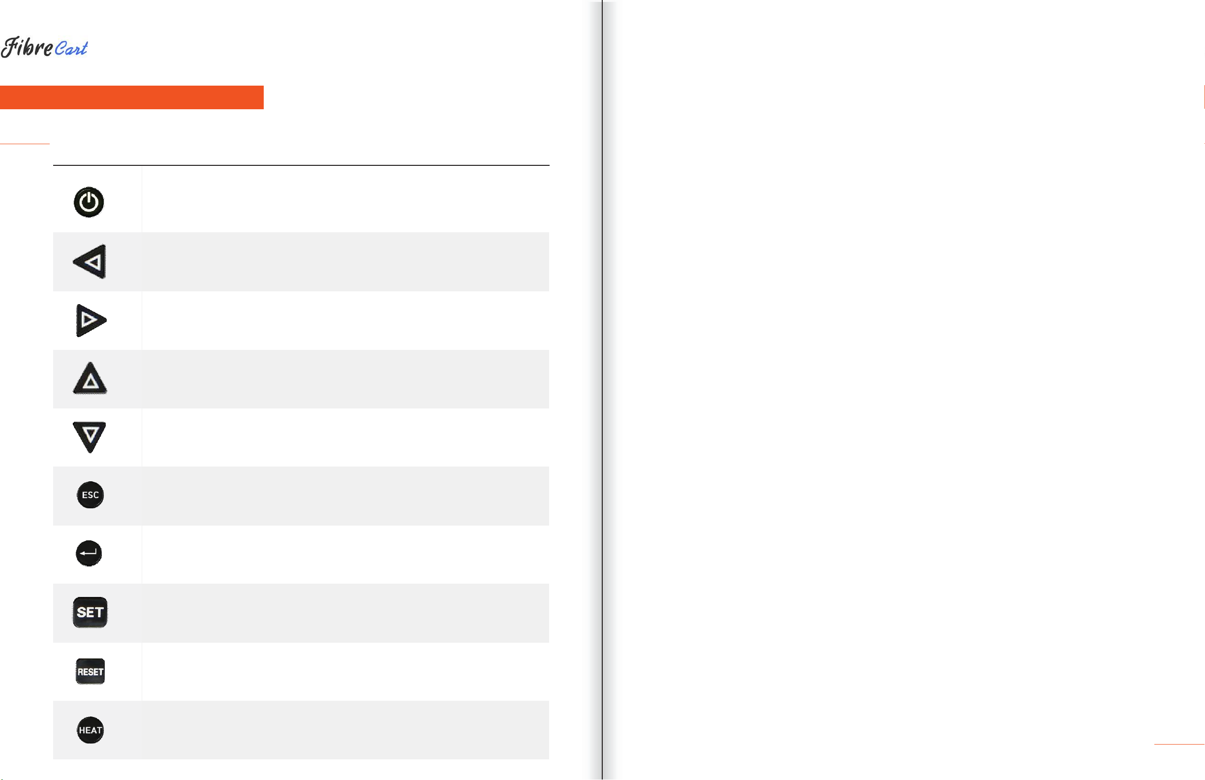
| FUNCTION BUTTONS
BUTTON DESCRIPTION
Press and hold about 1 second to turn the power on/off.
Move the cursor to the left.
Move fiber to manual mode and adjust the camera’s focus. Stripping popup
menu should load.
Move the cursor to the right.
Move fiber to manual mode and adjust the camera’s focus.
Move the cursor upward.
Move each motor to manual mode. Splice popup menu should load.
Move the cursor downward. Move each motor to manual mode. Heater
popup menu should load.
Initialize the splice function. Return to the menu screen.
Complete a selection.
Follow the next step on the menu screen.
Splice execution.
Return to the initial screen and initialize splice function.
Turn on the heater.
When it is on, the lamp on the left is in the red.
Press once more when it is on, and the heater is turned off.
7

3.2
| COMPONENT NAME
8
|
SLEEVE HEATER
|
WIND COVER
|
MONITOR
|
BATTERY
|
DC IN/CHARGE-IN
|
USB
|
OPEN
|
HEATER
|
HEATER COVER

INSTRUCTIONS FOR USE
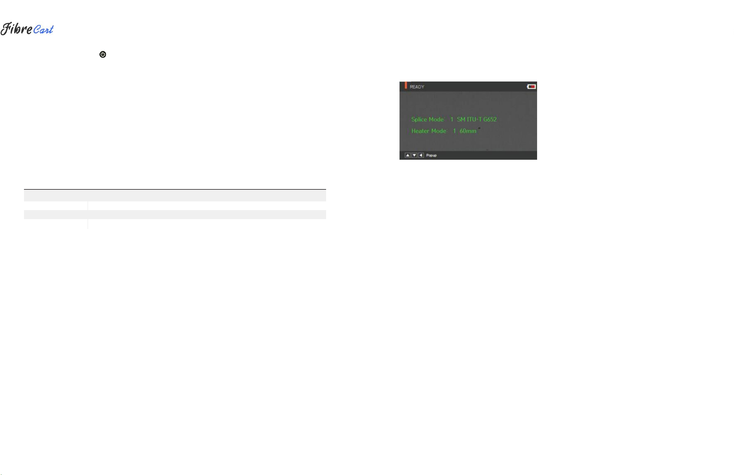
The following is the KF4’s initial screen. For accurate splice results, splice mode and heater mode should be
selected. Basic information about the KF4 is displayed on the initial screen. Check that the proper mode is
selected before splicing.
|
BATTERY STATUS INDICATOR
|
CURRENT SPLICE MODE
|
CURRENT HEATER MODE
4.1
| POWER SUPPLY
The battery pack is built into the battery chamber. Loosen the bottom-cover bolts and exchange the battery.
Please be cautious when you detach the battery from the chamber.
4.1.1
BUILT IN BATTERY
4.1.2
BATTERY CHARGING
Before connecting the AC/DC charter’s DC cable to the DC jack of the battery to charge the battery, make sure
you check the voltage and frequency. When the battery is fully charged, the LED will turn green and power is
disconnected, activating protection circuit to avoid overcharge. The power is turned back on as the battery
needs to be charged. Charging resumes when the charger’s DC cable is connected to the battery’s DC jack.
9
4.2
| HOWTO TURN THE POWER ON/OFF
To power on the KF4, press and hold about 1 second with the wind cover closed. After the functions of
motors and initialize, the screen will display the following. Then splice and heater mode should be selected.
The current splice and heater mode are displayed at the bottom of the screen.
4.3
| KF4 SLEEVE HEATER
The sleeve heater of the KF4 reinforces the spliced point of the single
fiber.The quality of fusion splicing on the fiber should be good.
The fiber and inserted sleeve tube should be properly aligned and installed on the heater.
Close the heater cover while the heater is on.
ITEM DESCRIPTION
Cable diameter
250µm, 900µm, 2.0mm —3.0mm
Sleeve length
Standard 32mm
Heating time
10 —35 seconds
Temperature range
130°C —200 °C
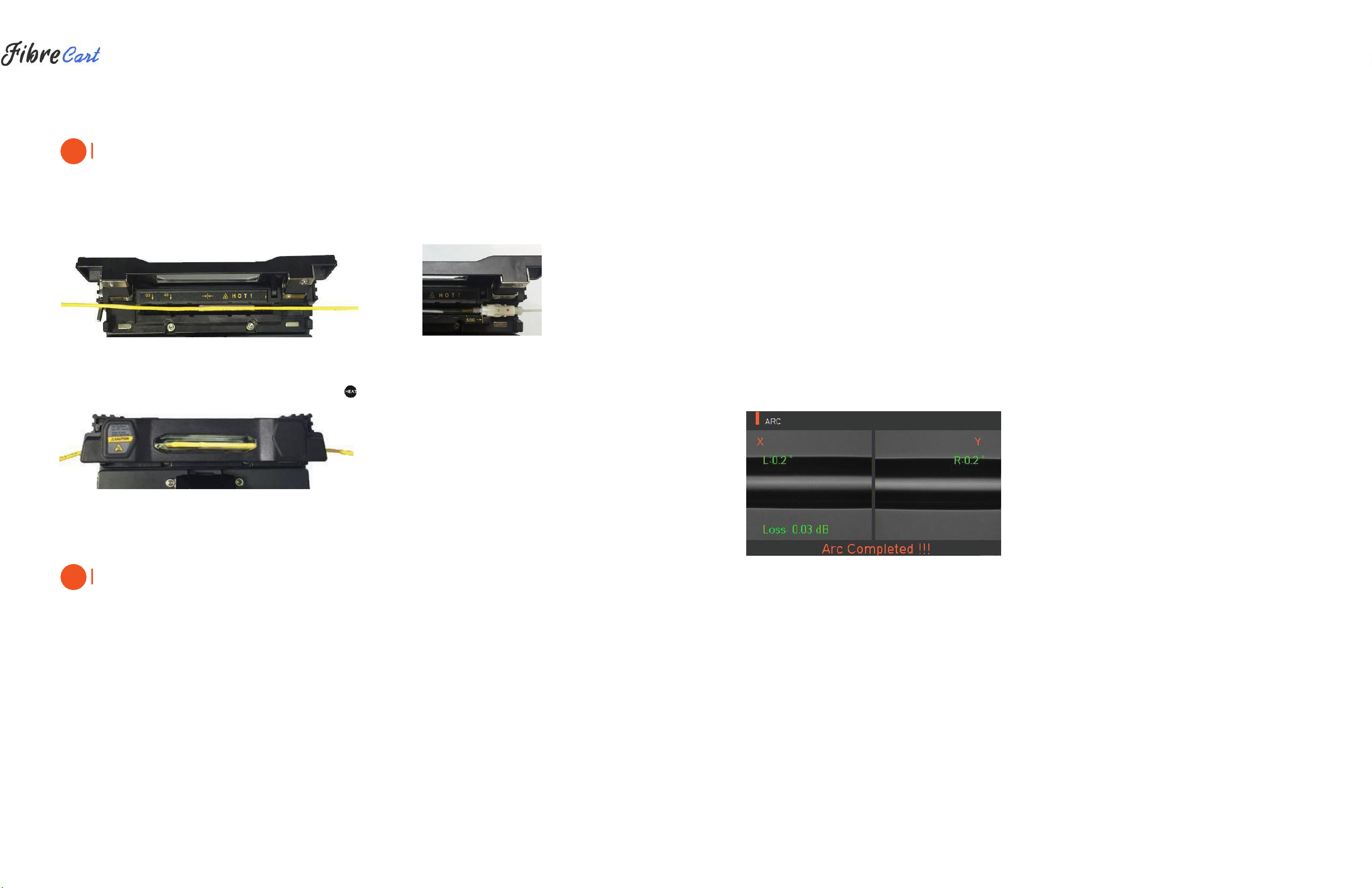
1| Choose the heater mode after the confirmation of the length for the sleeve tube when placing a sleeve tube
on a heater.
2| Place the spliced point in the middle of the sleeve tube first. Then, check the heating part on the heater and
place the sleeve tube on right position.
10
CAUTION
Choosing the improper mode of the heater for a sleeve tube may not shrink the sleeve tube properly. Specifically,
the SOC (Splice-On-Connector) should be placed on the right side edge of the heater in order to line up the
right end of the sleeve tube to the right side edge of the heater as shown on the picture below (Right picture). If
the SOC is placed in the middle or on the left side, the sleeve tube of the SOC does NOT shrink.
|
OPTICAL FIBER
|
SOC CONNECTOR
3| After settling the fiber, turn on the heater by pressing . (Heating time 20sec)
4| Remove the sleeve protected fiber by opening the cover when the cooling is completed.
CAUTION
The appropriate sleeve position helps reduce heating operation time.
4.4
| SPLICE PROCEDURE
The status and cleaved quality of the fiber can be monitored by using a KF4 image processing system.
However, for better splice results, visual inspection is also required.
In auto mode, the splicing procedure begins automatically as the wind cover is closed.
1| Fibers installed on the splicer advance toward each other and stop. The fibers align once arc cleaning is
done. After that, the splicer checks the cleaved angle of each fiber, the shape of the end-face contaminations
and so on. When the measured cleaved angle is bigger than the preset value, or damage is detected on the
fiber, an error message is displayed on the screen. The splice procedure stops as well. Even if there is no error
message displayed, visual inspection of the monitor screen is always recommended.
2| Check that the Wind cover is properly closed at more than 900µm cable (Ø2.0~Ø3.0µm)
3| Fibers are aligned, cladding to cladding, after inspection. Deviation on clad axis can be displayed on
the screen.
4| After alignment completes, arcing is conducted to splice fibers.
5| After splicing is completed, the estimated value of the loss is displayed on the screen. The estimated value of
splice loss is subject to various factors related to the error. These factors related to an error affect the estimation
and calculation of estimated loss value as well. Calculation of estimated loss is based on factors such as MFD.
When estimated loss value exceeds the preset value, an error message is displayed on the screen. The error
message is also displayed when the spliced fibers are too thick or thin, or when bubbles are generated on the
spliced point. If the splice result shown on the screen is not considered good enough, it is recommended that
splicing be conducted again.
6| The splice result is saved as follows.
7| When splice is completed, the splice result is automatically saved.
4.5
| REMOVING THE SPLICED FIBER
1| Open the cover of the sleeve heater.
2| Open the wind cover.
3| Hold the fiber on the left and open the clamp on the left.
4| Open the fiber clamp on the right.
5| Hold both sides of the spliced fiber and separate the fiber from the KF4 with care.
4.6
| HEATING PROTECTION SLEEVE
1| Move the spliced point to the center of the protecting sleeve. Place the protected pin face down in the sleeve.
2| Place the protecting sleeve at the center of the sleeve heater.
!
!

3| Hold and put down both fibers as shown in the figure. The heater cover will automatically close.
11 12

4| Heating starts by pressing .
5| LED turns off when heating is completed.
6| Open the heater cover and take out the fiber. Do not touch the protecting sleeve or heater at any point
during or right after heating.
7| Conduct a final inspection to check for bubbles, fragments or dust on the sleeve.
4.7
| USE OF WORK BELT
The work belt of Swift KF4 is a type of auxiliary equipment that combines with its main body to facilitate
working at a manhole, utility pole, etc.
|
WORK BELT COMPONENTS
MAINTENANCE OF SPLICE QUALITY
5.1
| CLEANING AND INSPECTION BEFORE SPLICE
5.1.1
V-GROOVE CLEANING
When the inside of the V-groove is contaminated, splice quality may deteriorate. It is important to regularly
inspect and frequently clean the V-groove as follows.
1| Open the wind cover.
2| Clean the V-groove using a cotton swab moistened with alcohol and any proper cleaning agents. Remove
the remaining alcohol from the V-groove using a clean, dry, lint-free cotton swab.
3| When a foreign substance cannot removed with a cotton swab, clean it with the tip of a cleaved fiber and
repeat the steps above.
5.1.2
PUSHER BLOCK CLEANING
Pusher block contamination causes poor splice quality due to irregular pressure applied to the fibers. It is
important to frequently inspect and regularly clean it.

13 14

5.2
|
REGULAR INSPECTION AND CLEANING
To ensure splicing quality, regular inspection and cleaning are required.
5.2.1
OBJECT LENS CLEANING
Contamination on the object lens surface disturbs the identification of fiber core location and consequently
causes high splice loss. Object lenses should be kept clean at all times. If dust accumulates for a prolonged
period, it may be difficult to remove. Clean the lens frequently as follows.
1| Turn the power off before cleaning the object lens.
2| Separate the electrodes.
3| Use a soft cotton swab moistened with alcohol to clean in a circular motion from the center as shown in the
figure below. Dry the remaining alcohol using a clean, dry, lint-free cotton swab.
4| The surface of the object lens should be clean without any lines or stains.
5| Reassemble the electrodes.
6| Turn the power on and check for any lines or stains on the monitor. Conduct a self-diagnosis.
5.2.2
ELECTRODES REPLACEMENT
The electrodes should be replaced after being used approximately 4000 times. If the number of arcs exceeds
the replacing cycle, an electrode replacement message is displayed on the screen. If electrodes are not
replaced, splice loss increases and the tensile force at the splicing point weakens.
1| Turn the power off when replacing the electrodes.
2| Open the wind cover and unscrew the clamp screw on the electrodes block.
3| Remove the electrode block and the electrodes.
4| Clean the electrodes carefully by using a soft cotton swab moistened with alcohol, then install.
5| Turn the power on and conduct the electrode stabilization process in the menu.

15 16

MENU
The main menu has eight submenus. Press to load the main menu.
The eight submenus can be selected by using , or by pressing the screen. The main menu
screen displays as follows.
SPLICING
•
Replace: Selects and replaces a certain splice mode within the database
•
Add: Selects and adds a certain splice mode within the database
•
Select: Selects a splice mode to run
•
Edit: Edits set values of splice mode
•
Cancel: Closes the menu window
•
Delete: Deletes splice mode
HEATER
•
Replace: Selects and replaces a certain heater mode within the database
•
Add: Selects and adds a certain heater mode within the database
•
Select: Selects a heater mode to run
•
Edit: Edits set values of heater mode
•
Cancel: Closes the menu window
•
Delete: Deletes heater mode
HISTORY (SPLICE RESULTS)
•
DISPLAY HISTORY: Displays splice result and image
•
CLEAR HISTORY: Deletes all data
OPTION
•
DEFAULT: Auto, pause, auto heater
•
MENU LOCK: Menu lock setting
•
PASSWORD: Password sets upon locking
CALIBRATION
•
ARC CALIBRATION: Adjusts arc calibration intensity
•
ARC TEST: Check arc quantity through arc test
•
DIAGNOSTIC TEST: Diagnoses equipment state
•
MOTOR DRIVE: Operates motor manually
•
MOTOR CALIBRATION: Initializes motor speed and location
ELECTRODE
•
ELECTRODE STABILIZE: Conducts stabilization of electrodes
•
ELECTRODES CAUTION: Sets the number of uses to inform about electrode replacement
•
ELECTRODES REPLACE: Explains how to replace the electrodes
•
ELECTRODE USED: Displays the electrode-use count
SETTING
•
LANGUAGE: Selects a language
•
DATE: Sets the present time
•
POWER SAVE: Sets sleep mode
•
VOLUME: Adjusts the intensity of the buzzer sound
•
LCD BRIGHTNESS: Adjusts screen brightness
INFORMATION
•
MAINTENANCE INFO: Displays maintenance schedule
•
SENSOR VALUE: Indicates temperature and pressure
•
VERSION: Shows the current version of the product
•
HELP: Consists of:
—
NAME OF PARTS
—
CLEAN AND INSPECT
—WARNINGS
—
A/S CONTACT LIST

17 18

POPUP MENU
The purpose of the popup menu is to facilitate quick, easy access to the splice mode and heater mode. The
user can access the popup menu in various ways.
[Displaying popup menu]
1| Splice popup menu can display the current splice mode by pressing on the initial screen.
2| Heater popup menu can be displayed by pressing on the initial screen.
[Splice popup menu]
ADDING SPLICE MODE
1| Display splice popup menu by pressing on the initial screen.
19
Table of contents
Popular Welding Accessories manuals by other brands

Lincoln Electric
Lincoln Electric VIKING 3350 Series Operator's manual

STAYER WELDING
STAYER WELDING GS-0 operating instructions

Chicago Electric
Chicago Electric 61610 Owner's manual & safety instructions

Amada
Amada MK-110B Operation manual

Sealey
Sealey PWH620.V2 Instructions for use

AMERICAN WELDQUIP
AMERICAN WELDQUIP 607CG manual


