CK WORLDWIDE PC2000-24-220V User manual

CK
Worldwide,Inc.
1
How To Use Your New Flexible Purge Chamber
January,2000
CKWorldwide,Inc.
P.O.Box1636Auburn,WA.USA98071
tel:(253)854-5820
fax:(253)939-1746
www.ckworldwide.com
NOTE: Theimportantsafeguardsandinstructionsappearingin
thispamphletshouldbereadandunderstoodpriorto
operatingyourequipment.
SafetyGuidelines ........................................................................................................................
Warranty ...............................................................................................................................
Introduction ..........................................................................................................................
Description ............................................................................................................................
Specifications ........................................................................................................................
Checklist ...............................................................................................................................
Optionalitems ......................................................................................................................
Suggestions ............................................................................................................................
Assembly ...............................................................................................................................
Installation ............................................................................................................................
Operation ..............................................................................................................................
Questions ..............................................................................................................................
TechnicalData .......................................................................................................................
TABLEOFCONTENTS:
2
4
4
4
5
5
6
6
6
6
7
7
8
2
CK Worldwide, Inc.
SAFETYRULES: WARNING: UNSAFEPROCEDURESORPRACTICESCANCAUSE
SERIOUSPERSONALINJURYORDEATH.
All end users of this equipment, the operators and helpers, read and
understand these safety rules.
PREVENTELECTRICALSHOCK:
Touching live electrical parts can cause severe burns or fatal shock.
1. Do not touch live electrical parts.
2. Do not work in wet or damp areas.
3. Wear dry insulating gloves and body protection.
4. Disconnect all power before installing or servicing this equipment.
5. Turn off all equipment when not in use.
6. Properly install and ground the welding power source according to
its Owner's Manual and all applicable codes.
7. Do not use worn or damaged cables or cables that are too small or
poorly spliced.
8. Do not wrap cables around your body.
9. Do not touch electrode and any grounded object or circuit at the
same time.
10. Use only well-maintained equipment. Repair or replace damaged
parts at once.
PROVIDEPROTECTIONFROMFUMESANDGASES:
Breathing welding fumes and gases can be hazardous to your health.
1. Keep your head out of welding fumes.
2. Use adequate ventilation in the work area to keep fumes and gases
from your breathing zone and the general work area.
3. If ventilation is inadequate, use an approved breathing device.
4. Read and understand the Material Safety Data Sheets (MSDSs) and
the manufacturer's instructions for any materials used.
Gas cylinders are normally used when welding, treat them with care.
PROTECTCOMPRESSEDGASCYLINDERS:
1. Protect compressed gas cylinders from excessive heat, mechanical
shocks and arcs.
2. Install and secure cylinders so that they cannot fall or tip over by
fastening them to a mounting bracket, wall or other stationary
support.
3. Keep cylinders away from any welding or other electrical circuits.
4. Never allow a welding electrode to touch any cylinder.
PROTECTEYESANDSKINFROMARCRAYS,PROTECTEARS
FROMNOISE:
Welding arc rays produce intense heat and ultraviolet rays that can burn
eyes and skin. Noise from some processes can also damage hearing.
1. Wear a welding helmet fitted with a proper filter lens (see ANSI
Z49.1 for detailed information).
2. Use protective screens or barriers to protect others from welding
flash and glare.
3. Wear protective clothing and foot protection.
3
Purge Chamber Manual
The hot workpiece, hot equipment, spatter, and arc sparks can cause
fires and burns.
1. Wear correct eye, face, and body protection in the work area.
2. Allow work and equipment to cool before handling.
3. Do not weld near flammable materials.
4. Watch for fire, and keep a fire extinguisher nearby.
5. For additional information, refer to NFPA Standard 51B, "Fire
Prevention in Use of Cutting and Welding Processes", available
from the National Fire Protection Association, Batterymarch Park,
Quincy MA 02269.
PREVENTFIRESANDBURNS:
PROVIDEPROTECTIONFORSPECIALSITUATIONS:
1. Do not weld or cut containers or materials which have held or been
in contact with hazardous substances unless they are properly
cleaned and inspected.
2. Do not weld or cut painted or plated parts unless special ventilation
is provided to remove highly toxic fumes or gases.
3. Since welding can affect pacemakers, keep all pacemaker wearers
out of the work area. Have them consult a doctor before coming
near a welding operation.
PROVIDEPROPEREQUIPMENTMAINTENANCE:
Improperly maintained equipment can result in poor work, but most
importantly it can cause physical injury or death through fires or
electrical shock.
1. Always have qualified personnel perform the installation,
troubleshooting, and maintenance work. Do not perform any
electrical work unless you are fully qualified.
2. Before performing any maintenance work inside a power supply,
disconnect the power supply from the electrical power source.
3. Maintain cables, grounding wire, connections, power cord, and
power supply in a safe working order. Do not operate any
equipment in questionable condition.
4. Do not abuse any equipment or accessories. Keep equipment away
from heat sources such as furnaces, wet conditions such as water
puddles, oil or grease, corrosive atmospheres, and inclement
weather.
5. Keep all safety devices, guards, panels, and covers in position and
in good repair.
6. Use equipment for its intended purpose. Do not modify it in any
manner.
SAFETYRULES:
For more information on safe practices for setting up and operating electric welding and
cutting equipment and on good working habits, ask your welding equipment supplier.
For your protection, read and comply with the latest editions of the following standards:
1. ANSI Standard Z49.1
2. ANSI Standard Z87.1
3. AWS Standard A6.1
4. AWS Standard F4.1
5. CSA Standard W117.2
6. NFPA Standard 51B
7. NFPA Standard 70
8. OSHA Standard 29 CFR, Part 1910,
Subpart Q
ADDITIONALSAFETYINFORMATION:

4
CKWorldwide,Inc.
WARRANTY: CKWorldwide,inc.warrantstheFlexiblePurgeChamberagainstdefectsin
materialsandworkmanshipforaperiodofoneyearfromthedateofpurchase.
Shoulditbecomedefectiveforsuchreason,themanufacturerwillrepairit
withoutcharge,ifitisreturnedtothemanufacturer'sfactory,freightprepaid.
Priortoreturningtheequipment,writtenauthorization,intheform ofanRGA
numbermustbeobtainedpriortoanyreturnsforanyreason. Thiswarrantydoes
notcover:(1)failureduetonormalwearandtear;(2)damagebyaccident,improper
use,neglect,unauthorizedrepairoralteration;(3)anyoneotherthantheoriginal
purchaser. Inanyevent,CKWorldwide,Inc.willonlyberesponsibleforits
productswhenusedwithaccessoryitemsmanufacturedbyCKWorldwide,Inc.
Thislimitedwarrantyisinlieuofallotherwarranties,expressedor implied.
Themanufacturershallnotbeliableforanyinjurytopersons,includingdeath;or
lossordamagetoanyproperty,directorconsequential,including,butnotlimited
tolossofuse,arisingoutoftheuse,ortheinabilitytouse,theproduct.Theuser
assumesallriskandliabilitywhatsoeverinconnectionwiththeuseofthis
product,andbeforedoingsoshalldetermineitssuitabilityforitsintendeduse,
andshallascertainthepropermethodofusingit. Thiswarrantygivesyou
specificlegalrights,andyoumayhaveotherrightswhichvaryfromstatetostate.
ThepatentedCKFlexiblePurgeChamberisusedintheGasTungstenArc
Welding(GTAW)/TungstenInertGas(TIG)processtoprovideacompletelyinert
atmospherefortheweldingofreactivemetalssuchastitanium,molybdenum,
nickel-basedandaluminum-basedalloys,aswellasnon-reactivemetalslike
stainlesssteel. Uniquetothisdesignistheabilitytodrawavacuumaroundthe
producttobeweldedwhichcollapsesthechamber,removingallatmospheric
gases. Thechamberisthenfilledthroughaperforatedhosethatcoversthe
circumferenceofthechamber. Thisfillingprocessallowstheargongastoexpel
allatmosphericgasesmoreeffectivelythantraditionalfillingmethods. This
significantlyreducesthetimerequiredtoreachatotallyinertatmospherethatis
suitableforweldingandusesconsiderablylessgasthanthetraditionalrigidpurge
chambers.
INTRODUCTION:
DESCRIPTION: TheFlexiblePurgeChamberisdesignedtorestonasupportdevicethatisthe
samediameterasthechamber'sbase. Whentheunitiscompletelydeflated,with
thechamber'swallsdrapedoverthesidesofthesupportbase,avacuumisdrawn
byeither1.)blowingcompressedairthroughtheexternalvacuum"Y"creatinga
venturicapableofexpellingtheatmosphericairinsidethechamber,or2.)
installinganauxiliaryvacuumpump. Onceavacuumisperformedthechamberis
theninflatedat35cubicfeetperhour(Excessivefillrateswillcauseturbulence
resultinginthemixingoftheargonshieldinggaswiththeairinthechamber
whichextendsthetimeittakestoobtainacompletelyinertatmosphere). The
purposeistodisplaceanyremainingatmosphericairouttheexhaustportonthe
topofthechamberusingargonwhichissignificantlyheavierthanair. Partscan
thenbeweldedinatotallyinertatmosphere.
Toremaincompetitiveinthedomesticandinternationalmarkets,weareallowing
customerstoprovidetheirownweldingtableandotheraccessoriestofitinside
thechamber.
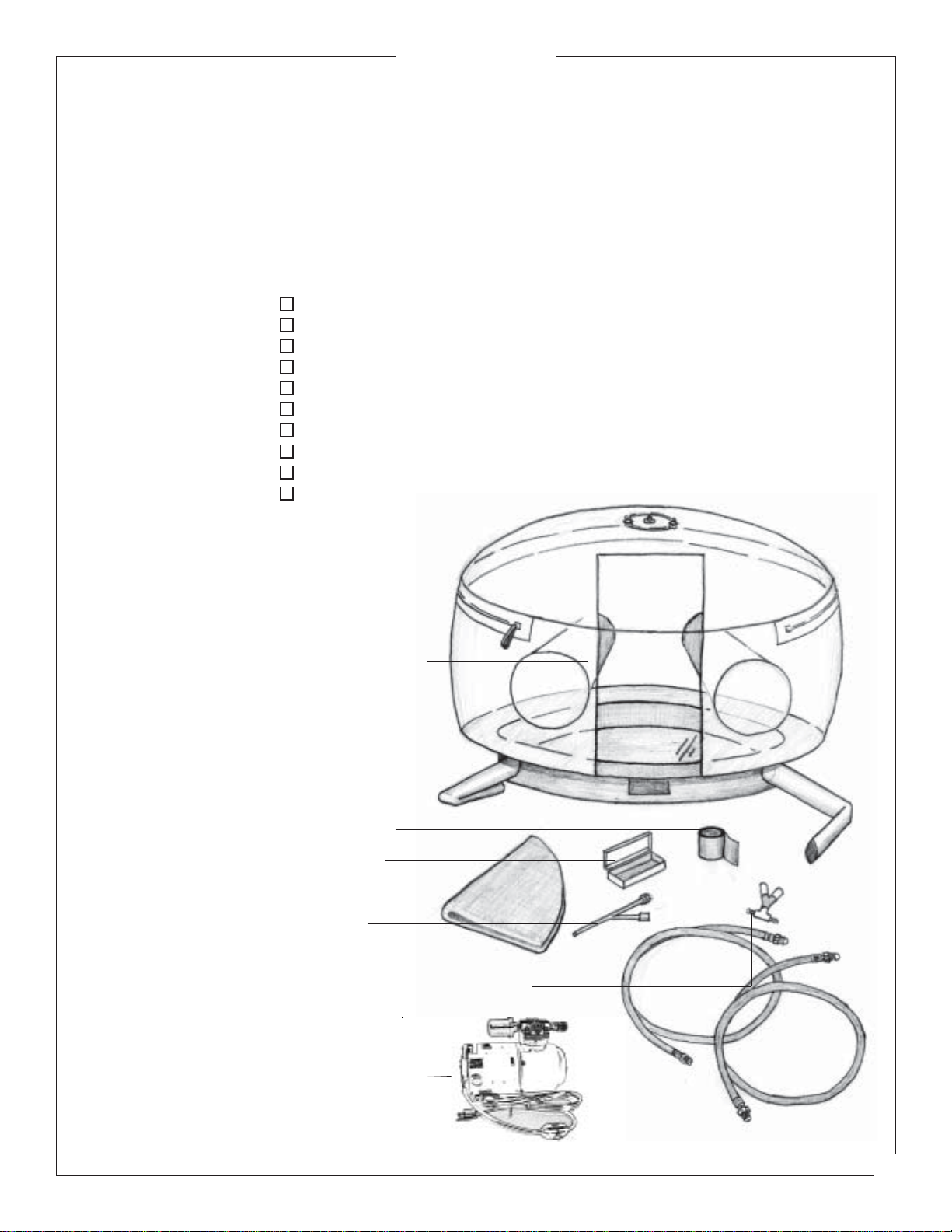
NeopreneGloves
RollofTape
TransparentFlexiblePurge
ChamberEnclosure
GasValveAssemblywithHoses
RepairKit
HeatBlanket
Venturi
5
PurgeChamberManual
SPECIFICATIONS: FLEXIBLEPURGECHAMBER:
20"
30"*
17lbs.
30"Diameter
30"RangeofMovement
24"Base
*Contactfactoryforpriceandavailabilityonothersizes.
Height:
Width:
ShippingWeight:
StandardSize*:
CHECKLIST: One(1)TransparentFlexiblePurgeChamberEnclosure
Four(4)NeopreneGloves-Two(2)Installed
One(1)RollofTape
One(1)RepairKit
One(1)HeatBlanket
One(1)Venturi
One(1)GasValveAssembly(installed)withHoses
One(1)ElectricVacuumPump
One(1)Flow-meter/RegulatorwithArgonhose
One(1)StorageContainer
VacuumPump

6
CKWorldwide,Inc.
OPTIONAL
ITEMS: TIGTorchandaccessories-refertoextravaluebrochure(form3000).
ColdWireFeedUnit.
Extraneoprenegloves.
SUGGESTIONS: 1. Ifweldedpartsaretoohottohandle,useforcedgascoolingwithasmallfan
tospeedupthecoolingprocessinsidethechamber. Donotuseleathergloves
insidethechamber,astheycancausecontamination.
2. Tokeephandscomfortable,cottonglovescanbeworninsideneoprene
gloves.
3. Thecomponentsbeingputintothechambermustbecleanedwithasuitable
solventanddried. Thepartsshouldbehandledwithcleanhands.
4. Donotcollapsechamberbeforepartshavecooled.
ASSEMBLY: Ifthechamberhasbeenexposedtotemperatureextremes,itshouldbeleftfor
severalhourstoreachroomtemperature. Prematureunpackingcouldleadto
cracking,scuffingand/ordeformation. Thechamberisquotedandnormally
suppliedinitsbareformandwillneedahardinternalbase,anexternalsupport
table,anargongassupplywithflowmeter,compressedair(forvacuumprocess),a
weldingtorchandgroundcable.
Unpackthechambercarefullytoavoidcracking,scratchingortearing. Placethe
chamberonapreparedtabletop,thesamediameterastheinnerbasering. At
thistimetheheatblanketshouldbeplacedontheplasticbaseinsidethechamber.
Asteelplateshouldthenbeplacedontopoftheheatblanket.Astainlesssteel
plateisrecommended(1/4"-1/2").Theblanketsedgeswillbeexposedaround
theperimeterinsidethechamber,toprotectthesidesofthechamber.
Note:Theheatblanketactsasalowtemperatureprotectorthatinsulatesthesteel
baseplatefromtheplasticbase.Theblanketisnotintendedtobeweldedon.
INSTALLATION: Insertthetorchassemblyintothechamberthroughoneoftheaccessoryports.
Youwillneedtopierceaholeattheportentranceofthechamber. Removeall
front-endpartsfromTIGtorch. Oncethetorchhasbeeninserted,usethetape
provided,orducttape,tosealtheportsleeveontothetorchcable. Theground
cableandotheraccessoriesshouldbeinstalledthroughoneoftheaccessoryports
inthesamemanner,thensealed.
Connectthegashoseassemblytothechamberatthe1/4"NPTinlet. Next,
connectthehosecomingfromthe"Y"labeled"GAS"toaregulator/flowmeter.
Theunitisnowreadytohavepartsinsertedforwelding.

7
PurgeChamberManual
OPERATION: Ensurethereissufficienthighpurityargoninthepurgechambersupplybottle
andthetorchgassupplybottletocompleteallweldingoperations. Failureto
dothiswillresultintheintroductionofairduringabottlechangewhichwill
requirere-purgingofthesystem. Checktoensurethatallgaslinestothe
chamber,theweldingmachine,andregulator/flowmeteraretight. Also,check
toensurethatallaccessoryportsthatareinuseareproperlytaped. Check
glovesforanydamage.
Loadthecomponentsintothechamberandclosethezipper. Purgeoutthe
torchlines. Thechambercanbepresseddownaroundthepartstoexpelthe
majorityoftheair. Makesurethattheexhaustventonthetopofthechamber
isclosed. Tocompletethevacuumprocess,oneoftwomethodscanbeused:
1.)"Y"Vacuum:Compressedairisblownthroughtheinletofthe"Y"which
createsaventurieffect,extractingalloftheremainingairinthechamber,or
2.)ElectricVacuumPump:Plugpumpinto115VACcircuit,leaveonuntilall
airisvacatedfromthechamber.
Note:Makesurewhenperformingavacuumthatthevacuumvalveisopen
andthegasvalveisclosedonthegas"Y".
Atthistime,turnonargongassupply,openexhaustvalveontopofthe
chamber,makingsurevacuumvalveisclosedandgasvalveisopenongas"Y".
Theargonflowrateshouldnotexceed35cubicfeetperhour,otherwise
turbulencewillcausemixingoftheargonshieldinggaswiththeairinthe
chamber. Whenthechamberiscompletelyinflatedatestweldonapieceof
scrapmaterialshouldbeperformed. Ifanydiscolorationorcontaminationis
present,repeatthepurgeprocess.
QUESTIONS: Anyuserrequiringfurtheradviceinanymatterconcerninginstallation,
operation,maintenanceorsafetycancallorwrite:
CK Worldwide, Inc.
P.O.Box1636
Auburn, WA. 98071
tel:+ 1 253 854 5820
fax:+ 1 253 939 1746
www.ckworldwide.com

CK
Worldwide,Inc.
TUNGSTEN
ELECTRODE
SELECTOR
CHART:
ENDPREPARATION GRINDINGINSTRUCTIONS EXTENSIONINSTRUCTIONS
TUNGSTEN
PREPARATION: STANDARDPARTS
General Purpose:
Extension:
3 x Diameter from end of
cup.
GASLENSPARTS
General Purpose:
Extension:
3 x Diameter from end of
cup.
Maximumextension:
6 x Diameter from end of
cup.
(In draft-free areas)
Shapetungsten bygrindinglogitudinally,neverradially.
Removesharp pointtoleaveatruncatedpointwith a
flatspot. Diameterofflat spotdetermines amperage.
Theincludedangledeterminesweldbeadshapeand
size. Generally,astheincludedangleincreases,
penetrationincreasesandbeadwidthdecreases.
Usea 60grit orfiner aluminumoxide wheel.
Balltip byarcingon cleanmetalatlow
currentDCRP(EP)thenslowlyincrease
currenttoform thedesiredball
diameter.
DCSP(EN)
General Purpose:
Flat:
1/4to1/2xDiameter
Taper:
2 to 3 x Diameter
ACHF
General purpose:
Ball:
Max. 1 x Diameter
BASEMETAL
TYPE Ballseasily,tendstospitathighercurrents,
usedfor noncriticalweldsonly.
Ballswell,high current, littlespitting,good
arcstarts,goodstability.
Mediumerosionrate,highcurrentrange,little
spitting,good arcstarts,goodstability.
Lowesterosionrate,widestcurrentrange,no
spitting,best arcstarts,beststability.
Mediumerosionrate,mediumcurrentrange,
mediumspitting, goodarcstarts,best stability.
Lowerosionrate,wide currentrange,no
spitting,consistent arcstarts,goodstability.
Mediumerosionrate,mediumcurrentrange,
mediumspit, goodarcstarts,best stability.
Lowerosionrate,wide currentrange,no
spitting,consistent arcstarts,best stability.
Rapiderosionrateathighercurrents,low
currentrangerecommended,spittingonstarts.
Lowerosionrate,wide currentrange,no
spitting,consistent arcstarts,goodstability.
Mediumerosionrate,mediumcurrentrange,
mediumspitting, goodarcstarts,best stability.
Lowerosionrate,wide currentrange,no
spitting,consistent arcstarts,goodstability.
Lowerosionrate,widestcurrentrange,no
spitting,best (DC)arcstarts,best stability.
Rapiderosionrateathighercurrents,low
currentrangerecommended,spittingonstarts.
Lowerosionrate,wide currentrange,no
spitting,consistent arcstarts,goodstability.
Lowesterosionrate,highestcurrentrange,no
spitting,best (DC)arcstarts,best stability.
SHIELDGAS
ELECTRODE
TYPE
Pure(EW-P)
WELDING
CURRENT
DESIREDRESULT
MATERIAL
RANGE
75%Argon
25%Helium
50%Argon
50%Helium
75%Argon
25%Helium
75%Argon
25%Helium
75%Argon
25%Helium
Argon
Argon
Helium
Argon
75%Argon
25%Helium
75%Argon
25%Helium
75%Argon
25%Helium
75%Argon
25%Helium
Helium
Argon
75%Argon
25%Helium
Zirconiated
(EW-Zr)
2%Thoriated
(EW-Th2)
2%Ceriated
(EW-Ce2)
2%Thoriated
(EW-Th2)
2%Ceriated
(EW-Ce2)
2%Thoriated
(EW-Th2)
2%Ceriated
(EW-Ce2)
Zirconiated
(EW-Zr)
2%Ceriated
(EW-Ce2)
2%Thoriated
(EW-Th2)
2%Ceriated
(EW-Ce2)
2%Lanthanated
(EW-Ce2)
Zirconiated
(EW-Zr)
2%Ceriated
(EW-Ce2)
2%Lanthanated
(EW-Ce2)
ACHFGeneralpurposeAll
Only thin
sections Controlpenetration DCRP
DCSPGeneralpurposeAll
Increasepenetration
ortravelspeed
Onlythick
sections
Only thin
sections Controlpenetration ACHF
Increasepenetration
ortravelspeed
Onlythick
sections
DCSPGeneralpurposeAll
Only thin
sections Controlpenetration ACHF
Increasepenetration
ortravelspeed
Onlythick
sections
Aluminum
alloysand
Magnesium
alloys
Copperalloys
Cu-NIalloys
and
Nickelalloys
Mildsteels
Carbonsteels
Alloysteels
Stainlesssteels
andTitanium
alloys
TUNGSTENPERFORMANCE
CHARACTERISTICS
DCSP
DCSP
DCSP
TECHNICAL
INFORMATION
CHART:
WELDINGCURRENT (AMPS)
-TUNGSTENTYPE ARGON FLOW (CFH)
-FERROUSMETALS ARGON FLOW (CFH)
- ALUMINUM
AC
PURE AC
THORIATED DCSP
PURE DCSP
THORIATED STANDARD
BODY GASLENS
BODY STANDARD
BODY GASLENS
BODY
CUP
SIZE
ELECTRODE
DIAMETER
(inches)
.020 4 or 5 5-15 5-20 5-15 5-20 5-8 5-8 5-8 5-8
.040 4 or 5 10-60 15-80 15-70 20-80 5-10 5-8 5-12 5-10
1/16 4,5or6 50-100 70-150 70-130 80-150 7-12 5-10 8-15 7-12
3/32 6,7or8 100-160 140-235 150-220 150-250 10-15 8-10 10-20 10-15
1/8 7, 8 or 10 150-210 220-325 220-330 240-350 10-18 8-12 12-25 10-20
5/32 8or10 200-275 300-425 375-475 400-500 15-25 10-15 15-30 12-25
3/16 8or10 250-350 400-525 475-800 475-800 20-35 12-25 25-40 15-30
1/4 10 325-700 500-700 750-1000 700-1100 25-50 20-35 30-55 25-45
FormNo. 5702
CKWorldwide,Inc.
P.O. Box1636Auburn,WA.98071
tel: (206)854-5820
fax: (206)939-1746
8
Table of contents
Other CK WORLDWIDE Welding Accessories manuals


Popular Welding Accessories manuals by other brands


Lincoln Electric
Lincoln Electric K2613-5 Operator's manual

Antra
Antra Digital-Pro Series user manual

Kemper
Kemper VacuFil 125 operating manual

FRONIUS
FRONIUS TTG 1200 operating instructions

FRONIUS
FRONIUS TTB Series installation instructions

Mag-Torch
Mag-Torch MT 525 Safety and operating instructions