ILUMEN PIDBOX User manual

ILUMEN PID SOLUTION
ILUMEN PIDBOX LIGHT
INSTALLATION MANUAL
Ilumen PIDbox Light–Version 1.1
INDOOR
OUTDOOR

Ilumen
2
Installation Manual Ilumen PIDbox Light v1.2
TABLE OF CONTENT
1Information on this manual .................................................................................................................................4
1.1 Validity ................................................................................................................................................................4
1.2 Target group .....................................................................................................................................................4
1.3 Additional information.................................................................................................................................4
1.4Symbols...............................................................................................................................................................4
2Safety .............................................................................................................................................................................4
2.1 Appropriate usage..........................................................................................................................................4
2.2 Qualifications of skilled persons...............................................................................................................5
2.3 Safety precautions..........................................................................................................................................5
2.3.1 Electric shock..........................................................................................................................................5
2.3.2 Electrostatic discharge........................................................................................................................5
3Scope of delivery.......................................................................................................................................................5
4Product description.................................................................................................................................................5
5Mounting......................................................................................................................................................................6
5.1 Mounting location requirements .............................................................................................................6
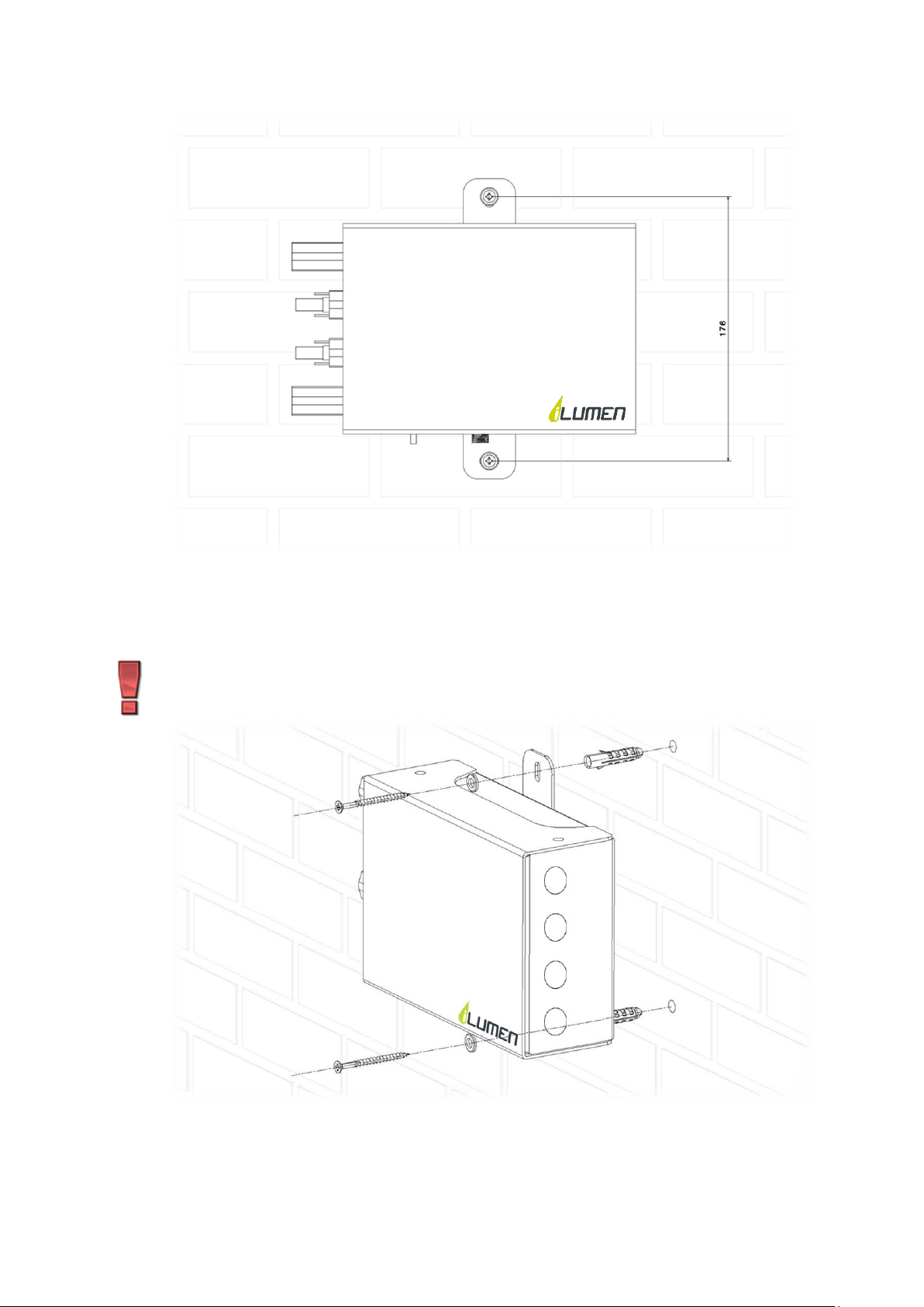
5.2 Mounting the Ilumen PIDbox Light using the wall brackets.........................................................6
6Electrical connections.............................................................................................................................................8
6.1 Earth connection.............................................................................................................................................8
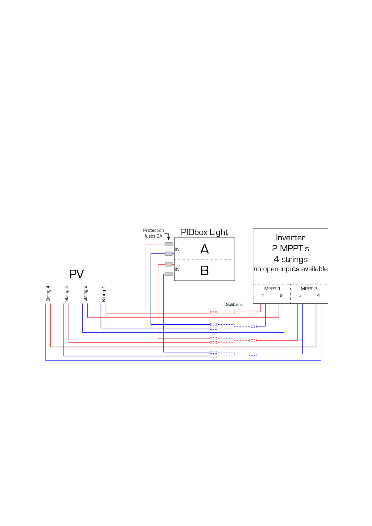
6.2 Solar array and inverter (MPPT) connections....................................................................................8
6.3 Connecting the solar modules ................................................................................................................10
6.3.1 Using splitter cables..........................................................................................................................10
6.3.2 Using the open inputs on the inverter.......................................................................................12
6.4 Protection fuses............................................................................................................................................13
6.5 Power supply.................................................................................................................................................14
6.6 The use of a RCD (residual current device) ......................................................................................15
7Commissioning.......................................................................................................................................................15
7.1 Check.................................................................................................................................................................15
7.2 Starting up the Ilumen PID Solution....................................................................................................15
8Installation summary...........................................................................................................................................16
9Decommissioning the Ilumen PID Solution................................................................................................17
9.1 Disassembling the PIDbox Light............................................................................................................17
9.2 Packing the PIDbox Light..........................................................................................................................17
9.3 Disposing of the PIDbox Light ................................................................................................................17
10 Troubleshooting................................................................................................................................................18

Ilumen
3
Installation Manual Ilumen PIDbox Light v1.2
10.1 Faults.................................................................................................................................................................18
10.2 No good PID regeneration........................................................................................................................18
10.3 Resetting the PIDbox Light ......................................................................................................................18
10.4 Repairing the PIDbox Light......................................................................................................................18
11 Contact ..................................................................................................................................................................19
12 Technical data....................................................................................................................................................20

Ilumen
4
Installation Manual Ilumen PIDbox Light v1.2
1INFORMATION ON THIS MANUAL
This manual contains instructions on how to install the Ilumen PIDbox Light.
1.1 VALIDITY
This manual applies to the Ilumen PIDbox Light.
1.2 TARGET GROUP
This manual is intended for skilled persons. Only qualified persons with the appropriate skills
are allowed to perform the tasks set forth in this manual.
1.3 ADDITIONAL INFORMATION
Links to additional information can be found at www.ilumen.be
✓Ilumen PIDbox Light datasheet
✓What is PID?
✓PID checker
1.4 SYMBOLS
Symbol
Explanation
Indicates a hazardous situation which, if not avoided, will result in
property damage
Indicates a hazardous situation which, if not avoided, will result in
death or serious injury
Information that is important for a specific topic or objective, but is not
safety-relevant
2SAFETY
2.1 APPROPRIATE USAGE
The Ilumen PIDbox Light applies a voltage to PV modules in reference to earth. The device may
only be switched on when the installation is done as described in this manual.
Before installing the Ilumen PIDbox Light, ensure that the permitted operating range of each
component is maintained at all times.
Before using the Ilumen PIDbox Light you have to obtain the appropriate approval from the
manufacturer of the PV modules and inverter.
Any applications other than those described here shall be considered contrary to the
appropriate usage. Alternative use or modification of the Ilumen PIDbox Light will void warranty
claims and operation permit.

Ilumen
5
Installation Manual Ilumen PIDbox Light v1.2
2.2 QUALIFICATIONS OF SKILLED PERSONS
The work described in this document must be performed by skilled personnel only. Skilled
personnel must have the following qualifications:
✓Knowledge of how an inverter works and how it is operated
✓Training in how to deal with the dangers and risks involved in installing and operating
electrical devices and plants
✓Training in the installation and commissioning of electrical devices and plants
✓Knowledge of all applicable standards and directives
✓Knowledge and observance of this document and all safety precautions
2.3 SAFETY PRECAUTIONS
2.3.1 ELECTRIC SHOCK
When the Ilumen PIDbox Light is in operation, voltage will be present. Prior to
maintenance work on the PV plant, switch off the Ilumen PIDbox Light.
When you want to change the arrangement of the Ilumen PIDbox Light you must switch
off the Ilumen PIDbox Light 20 minutes prior to making any changes.
2.3.2 ELECTROSTATIC DISCHARGE
Never operate the Ilumen PIDbox Light when not properly installed or when the
components are not closed properly. Always make sure the grounding of the Ilumen
PIDbox Light is done correctly.
3SCOPE OF DELIVERY
1. 1 x Ilumen PIDbox Light
2. 1 x DC power supply
3. 1 x Power cord (AC plug)
4. 4 x Rubber feet
5. 2 x Mounting bracket
6. 1 x Installation manual
4PRODUCT DESCRIPTION
The Ilumen PIDbox Light is placed in parallel over the solar array strings. The power of the
strings doesn’t go through the PIDbox. You can use one Ilumen PIDbox Light per 2 MPP trackers.
From each tracker, 2 wires will need to be connected to the PIDbox Light. In section 6 of this
manual a detailed description will be given to properly connect the PIDbox Light.

Ilumen
6
Installation Manual Ilumen PIDbox Light v1.2
5MOUNTING
5.1 MOUNTING LOCATION REQUIREMENTS
✓The installation site must be freely and safely accessible at all times without the
necessity for any auxiliary equipment.
✓The mounting location should be inside a rain- and windproof location.
✓Do not place the Ilumen PIDbox Light in a dusty environment.
✓The ambient temperature must be between -25 and 60°C.
✓Normally the PIDbox Light is installed right below the inverter.
✓The ideal placement of the PIDbox Light is on a flat surface. Special rubber feet can be
placed under the PIDbox Light to prevent scratching of any surface. Usage of the wall
brackets of the Ilumen PIDbox Light is needed when no flat surface is available. Always
install the box so that the power plug is pointing down.
Install the PIDbox on a flat surface to avoid stress on the mounting brackets.
Install the PIDbox always in a shaded area.
When having a lightning protection device installed between the PIDbox and the solar
panels, be aware of an increased chance on reduced regeneration.
5.2 MOUNTING THE ILUMEN PIDBOX LIGHT USING THE WALL BRACKETS
1. Mark the positions of the drill holes on the mounting surface

Ilumen
7
Installation Manual Ilumen PIDbox Light v1.2
2. Drill the holes
3. Insert the wall plugs (if necessary)
4. Screw the Ilumen PIDbox Light to the mounting surface and make sure adequate
washers are installed.
Make sure the DC power plug is pointing to the ground
5. Check if mounted securely

Ilumen
8
Installation Manual Ilumen PIDbox Light v1.2
6ELECTRICAL CONNECTIONS
When installing the Ilumen PIDbox Light, the AC side of the PV plant must be switched off. Also
the DC switch of the inverter must be switched off. After the installation is done, you can switch
the DC switch back on followed by the AC side of the PV plant.
A standard AC outlet must be available on installation. This outlet should be on at all times. The
ideal solution is to have a single outlet with a single circuit breaker of 16A.
6.1 EARTH CONNECTION
To achieve the best result, the frames of the solar modules must be connected to the earth
connector of the Ilumen PIDbox Light. For optimal result you must lay a cable (2.5-4mm2) to the
mounting structure of the solar modules (make sure mounting structures and frames of the solar
modules are electrically conducting). It is important that all frames of all solar modules are at
the earth potential, if necessary you have to interconnect the mounting structures with
additional cables.
6.2 SOLAR ARRAY AND INVERTER (MPPT) CONNECTIONS
When installing the PIDbox Light between the PV array and inverter always
switch off the DC switch of the inverter and/or in the DC combiner boxes.
When doing any kind of work on the PIDbox Light, always disconnect the
DC power plug from the device before unplugging any PV-cables.
Always connect the PIDbox Light in parallel with the PV arrays. On the Ilumen PIDbox Light the
“A PV in +” plug should be connected to the positive side of the strings of the 1st MPPT and the “A
PV in –“ plug should be connected to the negative side of the strings of the 1st MPPT. The strings
of a 2nd MPPT should be connected in the same manner to the “B PV in” plugs. You can use free
inputs on the inverter to make these parallel connections. If there are none available, you must
use a splitter cable to properly connect the PIDbox light
All unused inputs and outputs have to be terminated with a corresponding sealing plug.

Ilumen
9
Installation Manual Ilumen PIDbox Light v1.2
If you work with inverters with multiple MPPT’s you cannot mix the PV arrays
from multiple MPPT’s.
The maximum amount of PV-power that can be attached to 1 PIDbox Light is
100kWp. This is the total of panels attached to input A and B. Make sure this is not
exceeded to insure a good result.

Ilumen
10
Installation Manual Ilumen PIDbox Light v1.2
6.3 CONNECTING THE SOLAR MODULES
The maximum amount of PV-power that can be attached to 1 PIDbox Light is 100kWp. This is
the total of panels attached to input A and B. Make sure this is not exceeded to insure a good
result.
You can apply 2 ways of attaching solar modules to the PIDbox Light. One is with splitter cables
and the other is with using free inputs on your inverter. We will explain both ways in the
sections below.
6.3.1 USING SPLITTER CABLES
With the use of a splitter (1 to 2) you can simply hook up your PIDbox Light. Simply detach a
string from the 1st MPPT. Insert the splitter (the end with 1 connector) into the input from the 1st
MPPT of the inverter. Use the connectors on the other side of the splitter cable to connect the
solar array and the PIDbox Light A side. Make sure you connect the positive pole to the
“PV in A +” side of the PIDbox Light. Do the same for the negative side of the 1st MPPT. Make sure
you use the opposite splitter.
The 2nd MPPT is connected the same way as the 1st MPPT. Connect these 2 cables to the B-side of
the PIDbox Light.

Ilumen
11
Installation Manual Ilumen PIDbox Light v1.2
If you have an inverter with only 1 MPPT, you can use following hook up scheme. This way, you
will have 1 open input free for another inverter.

Ilumen
12
Installation Manual Ilumen PIDbox Light v1.2
6.3.2 USING THE OPEN INPUTS ON THE INVERTER
If your inverter has open inputs on the MPPT that you want to hook up, installation is quite easy.
You use these open inputs to connect the PIDbox Light. Plug in the “PV in A +” side of the PIDbox
Light to the positive open input of the 1st MPPT of the inverter. Then plug in the “PV in A -” side
of the PIDbox Light to the negative open input of the 1st MPPT of the inverter. Repeat these steps
for the 2nd MPPT. Attach these cables to the B side of the PIDbox Light.
If you have an inverter with only 1 MPPT, you can use following hook up scheme. This way, you
will have 1 open input free for another inverter.
The splitter cables from the PV plant to the PIDbox need to be fixed with brackets
to avoid stress on the connectors or the internal components of the PIDbox.

Ilumen
13
Installation Manual Ilumen PIDbox Light v1.2
6.4 PROTECTION FUSES
It is obliged to place protection fuses in front of the PIDbox Light. There are 2 ways of doing this.
The first is placing an electrical cabinet with din-rail fuse holders in it. The fuses must be rated
1000V DC and have a breaking current of 2Amps. The fuseholder also has to be rated 1000VDC.
Each input of the PIDbox Light must be protected by a fuse of 2Amps.
The second way is to place a cable/connector with fuses inside them like the picture below.
Again the fuse will need to have a 1000VDC rating and must break at 2 Amps.
or
It is obliged to place protection fuses in front of the PIDbox Light. The fuses must
be rated 1000V DC and have a breaking current of 2Amps. Each input must be
protected

Ilumen
14
Installation Manual Ilumen PIDbox Light v1.2
6.5 POWER SUPPLY
It is important that you only use the included DC power supply. When different power supply is
used, this will void warranty. First connect its DC side to the Ilumen PIDbox Light power input.
Next connect the AC side of the DC power supply to the unplugged power cord. You may connect
the DC side to the Ilumen PIDbox Light during installation. Don’t connect the AC side until
commissioning.
Make sure that locking nut of the DC-power plug for the outdoor version is
tightened for insuring a waterproof product
Make sure you always mount the power supply itself in a dry environment eg. in
the nearest inverter
Plug the not used connectors in to avoid water ingress into the PIDbox.
It is allowed to cut the power plug from the power cord in order to connect the
cables directly to a fuse/circuit breaker inside a power distribution box. It is only
allowed to cut the AC-cable and not the DC-cable going to the PIDbox Light
INDOOR
version
OUTDOOR
version

Ilumen
15
Installation Manual Ilumen PIDbox Light v1.2
6.6 THE USE OF A RCD (RESIDUAL CURRENT DEVICE)
Please consider the following advice. Certain inverters stay connected to the grid while other
inverters completely shut of the AC-side. Here are the 2 different situations.
•If the inverter, during the night, is disconnected from grid (normal condition) there is no
problems because the leakage current with respect to ground ,provided by PID box,
flows only into the solarpanels.
•If the inverter, during the night, remains connected to grid (this may happen if certain
functions are set into the inverter) the leakage current with respect to ground ,provided
by PID box, flows into both panels and the neutral wire (referred to ground in a TT
system). This leakage current flow inside the PV plant RCD.
If the AC output of more inverters with PID boxes are connected to a single RCD the sum of the
currents provided by PID boxes may cause the RCD tripping (i.e. 6 inverters with 6 PID boxes
can generate 6x5mA = 30 mA).
Always place the PIDbox Light behind a 300mA RCD to make sure the RCD is not
tripped because of the leakage current of the PIDbox Light. Also limit the number
of PIDboxes to 60 devices connected to 1 RCD of 300mA.
7COMMISSIONING
7.1 CHECK
Do a final check whether everything is properly mounted and connected (see chapter 5 and 6 for
details):
✓The PV frames are all connected to the same earth as the earth pin of the Ilumen PIDbox
Light
✓The PV and inverter DC cables are correctly connected
✓Unused DC inputs are terminated with a corresponding sealing plug
✓The DC side of DC power supply is correctly connected
If all these points are installed correctly you can start up the Ilumen PIDbox Light.
7.2 STARTING UP THE ILUMEN PID SOLUTION
The Ilumen PIDbox Light can only work in an automatic mode. To start up the Ilumen PIDbox
Light, plug in the DC power supply into a standard AC outlet (This outlet must be on at all times).
Next see if the LED light on the Ilumen PIDbox Light starts burning. After checking the system it
will be switched on automatically.
When the Ilumen PIDbox Light is hooked up correctly to the inverter you will see the following
status LED readouts.

Ilumen
16
Installation Manual Ilumen PIDbox Light v1.2
✓RED FAST BLINKING: power supply connected but no active solar system
detected
✓BLUE BLINKING: active solar system detected and waiting for activation (30
minutes waiting period.) This is normal startup behavior.
✓BLUE CONTINIOUS: active solar system detected and activated, ready for curing
at night
✓GREEN BLINKING: all startup conditions are met and PIDbox Light will start in
less than 30 minutes
✓RED: PIDbox Light active at night time
✓PURPLE: (OUTDOOR only) purple led can burn at night time. May switch to RED
It is normal for the LED to be out at the beginning and at the end of the night
After start-up you may turn the DC switch of the inverter back on, followed by the AC side of the
PV plant.
8INSTALLATION SUMMARY
1) Take the necessary safety precautions (AC side of the PV plant off and DC switch of the
inverter off).
2) Mount the Ilumen PIDbox Light on a flat surface or if not available mount it correctly to a
wall using the wall bracket.
3) Connect the Ilumen PIDbox Light earth pin to the frames of the PV modules and check
the interconnections between the PV casings.
4) Disconnect the PV array cables from the inverter.
5) Connect the PV array cables to the Ilumen PIDbox Light inputs (see 6.2 for details).
6) Connect the DC power supply to the Ilumen PIDbox Light.
7) Plug the DC power supply into an outlet (LED of the Ilumen PIDbox Light lights up if the
PVs are producing electricity)

Ilumen
17
Installation Manual Ilumen PIDbox Light v1.2
8) Turn the DC switch from the inverter back on followed by the AC side of the PV plant
9DECOMMISSIONING THE ILUMEN PID SOLUTION
9.1 DISASSEMBLING THE PIDBOX LIGHT
Switch off the Ilumen PIDbox Light. Disconnect the Ilumen PIDbox Light from the AC grid. Wait
for minimum 20 minutes. Make sure the AC cannot be plugged in again. Disconnect the DC
switch from the inverter and wait until it is discharged. Disconnect all DC connectors going to
the PV arrays and then disconnect the lines going to the inverter. When all electrical connections
are disconnected you can dismount the Ilumen PIDbox Light.
When doing any kind of work on the PIDbox Light, always disconnect the
DC power plug from the device before unplugging any PV-cables.
9.2 PACKING THE PIDBOX LIGHT
To pack the PIDbox Light use the original packaging or packaging suitable for the weight and
dimensions of the PIDbox Light (see Section 12 "Technical Data").
9.3 DISPOSING OF THE PIDBOX LIGHT
Dispose of the PIDbox Light at the end of its service life in accordance with the disposal
regulations for electronic waste currently applicable at the installation site.
3
7
8

Ilumen
18
Installation Manual Ilumen PIDbox Light v1.2
10TROUBLESHOOTING
10.1 FAULTS
LED readout
Fault
Corrective action
No leds visible
Product does not work
Make sure the DC-power supply is
plugged into a AC-outlet. Also make
sure the outlet is under tension.
No leds visible
Product does work and
makes some clicking
noises
This can happen at dusk and dawn. LED
should light up after a while. If not
please contact iLumen technical
service.
Led gives other color
than BLUE, GREEN,
WHITE, CYAN,
PURPLE or RED
Product does not work
Please contact iLumen technical
service.
No RED or PURPLE
led during nighttime
while during the day
blue led is burning
Curing of the panels is not
working
This can have 2 reasons:
•PID is not present on PV-
modules (however the first
night of regeneration the led
must be on).
•Earth connection between
PIDbox Light and the frame of
the modules is interrupted
Red led blinking
during the night
Product does not work
If you connected the PIDbox when it
was already dark outside, the PIDbox
will not become active during that 1st
night. Normally the PIDbox Light
should work the nights after that when
the solar plant has been active during
the day.
10.2 NO GOOD PID REGENERATION
If the modules are not regenerating or not regenerating fast enough you should check following
things:
✓Check the grounding of the system. If necessary you should place additional
interconnections between the frames of the modules.
✓Is the Ilumen PIDbox Light properly connected to the grid?
✓Is the DC power supply properly connected (is its indication light burning)?
✓Let an expert check if the problem you’re having with the yield is caused by PID
10.3 RESETTING THE PIDBOX LIGHT
The PIDbox Light can simply be reset by unplugging the DC-power cable. Wait 10 seconds and
connect the DC-power cable back to the PIDbox Light.
If resetting does not help fixing your problem, please consult chapter 10.1 of this manual.
10.4 REPAIRING THE PIDBOX LIGHT
Do not try to open up the PIDbox Light by yourself. This will void the warranty

Ilumen
20
Installation Manual Ilumen PIDbox Light v1.2
12TECHNICAL DATA
Technical data
ILUMEN PIDBOX LIGHT
PV array / inverter input
Input PV voltage range
80 - 1000 V
Output voltage to ground
Up to 1000 V
Maximum total PV power
100 kWp (c-Si)
Maximum output current in operation
5 mA
GRID (AC)
Nominal AC voltage
100 to 240 V
Nominal AC grid frequency
47 to 63 Hz
Power consumption in standby operation
< 0.2 W
Typical power consumption in operation
8 W
Maximum power consumption
20 W
General data
Dimensions (W x D x H)
270 x 200 x 75 mm
Weight
1.100 g
Operating temperature range
-25 to 60 °C (-13 to 140 °F)
Environmental conditions
Indoor version - IP30 - indoor use only
Outdoor version - IP65 –indoor / outdoor use (power supply IP30)
PV connectors
MC4
Configuration
Maximum two MPPT per PIDbox Light
Maximum one MPPT per input (A/B)
None of the connected solar module poles may become grounded
1 screw connection for grounding the frames of the PV modules
The inverter manufacturer’s approval is needed to place the PIDbox LIGHT
The client is responsible for getting the approval
This product will function with p-type solar cells.
If you want to apply this product to another technology, please contact iLumen
Various
Warranty
Up to 20 years
Certificates
www.ilumen.be
Registration before use
www.myilumen.be
Other manuals for PIDBOX
2
Table of contents
Other ILUMEN Inverter manuals
Popular Inverter manuals by other brands

Haier
Haier SUPER MATCH AS35S2SF1FA-BC Service manual

Solahart
Solahart SolarEdge Energy Bank owner's manual

SAJ
SAJ R5 Series user manual

Goodwe
Goodwe MT series Quick installation guide

Chicago Electric
Chicago Electric 91813 instructions

Mitsubishi Electric
Mitsubishi Electric FR-A500 Series Technical manual

Winco
Winco ULPSS20B2W/A Installation and operator's manual

Yamaha
Yamaha FB-01 owner's manual

Generac Portable Products
Generac Portable Products 005793-0 owner's manual

TOYODenki
TOYODenki VF66 EIP66-Z Communication Protocol Manual

Victron energy
Victron energy Phoenix Inverter Smart 12/1600 manual

Panasonic
Panasonic S-160PE1R5A Technical data and service manual