ILX Lightwave MPS-8033 Series User manual

-~
ARTISAN
®
~I
TECHNOLOGY
GROUP
Your definitive source
for
quality
pre-owned
equipment.
Artisan Technology
Group
Full-service,
independent
repair
center
with
experienced
engineers
and
technicians
on staff.
We
buy
your
excess,
underutilized,
and
idle
equipment
along
with
credit
for
buybacks
and
trade-ins
.
Custom
engineering
so
your
equipment
works
exactly as
you
specify.
•
Critical
and
expedited
services
•
Leasing
/
Rentals/
Demos
• In
stock/
Ready-to-ship
•
!TAR-certified
secure
asset
solutions
Expert
team
ITrust
guarantee
I
100%
satisfaction
All
tr
ademarks,
br
a
nd
names, a
nd
br
a
nd
s a
pp
earing here
in
are
th
e property of
th
e
ir
r
es
pecti
ve
ow
ner
s.
Find the Newport / ILX Lightwave MPS-8033 at our website: Click HERE

User’s Guide
Precision Fiber Optic Sources
MPS-8033 Series
ILX Lightwave Corporation P. O.Box 6310 Bozeman, MT, U.S.A. 59771 :· · · 1-800-459-9459 · ·
www.ilxlightwave.com
U.S. & Canada International Inquiries: 406-586-1244 Fax 406-586-9405
E-mail: [email protected]
700352_7/01
Artisan Technology Group - Quality Instrumentation ... Guaranteed | (888) 88-SOURCE | www.artisantg.com

Artisan Technology Group - Quality Instrumentation ... Guaranteed | (888) 88-SOURCE | www.artisantg.com

MPS-8033 i
!
! ! ! ! ! ! ! ! ! ! ! ! ! ! ! ! ! !
TABLE OF CONTENTS
List of Figures. . . . . . . . . . . . . . . . . . . . . . . . . . . . . . . . . . . . . . . . . . . . . . . . . . . . . . vii
List of Tables. . . . . . . . . . . . . . . . . . . . . . . . . . . . . . . . . . . . . . . . . . . . . . . . . . . . . . . ix
Safety and Warranty Information . . . . . . . . . . . . . . . . . . . . . . . . . . . . . . . . . . . . . xi
Safety Information and the Manual . . . . . . . . . . . . . . . . . . . . . . . . . . . . . . . . . .xi
General Safety Considerations . . . . . . . . . . . . . . . . . . . . . . . . . . . . . . . . . . . . .xi
Safety Symbols . . . . . . . . . . . . . . . . . . . . . . . . . . . . . . . . . . . . . . . . . . . . . . . . . . . . . xii
Safety Marking Symbols . . . . . . . . . . . . . . . . . . . . . . . . . . . . . . . . . . . . . . . . . . xii
Warranty . . . . . . . . . . . . . . . . . . . . . . . . . . . . . . . . . . . . . . . . . . . . . . . . . . . . . . . . . xiii
Limitations . . . . . . . . . . . . . . . . . . . . . . . . . . . . . . . . . . . . . . . . . . . . . . . . .xiii
Returning an Instrument . . . . . . . . . . . . . . . . . . . . . . . . . . . . . . . . . . . . . .xiii
Claims for Shipping Damage . . . . . . . . . . . . . . . . . . . . . . . . . . . . . . . . . . .xiii
Comments, Suggestions, and Problems . . . . . . . . . . . . . . . . . . . . . . . . . . . . .xiv
Chapter 1 Introduction and Specifications
Product Overview . . . . . . . . . . . . . . . . . . . . . . . . . . . . . . . . . . . . . . . . . . . . . . . . . . . 1
MPS-8033 Precision Fiber Optic Sources . . . . . . . . . . . . . . . . . . . . . . . . . . . . . 1
MPS-8033 Broadband 1550 nm ASE Fiber Optic Sources . . . . . . . . . . . . . . . . 1
Safety Considerations . . . . . . . . . . . . . . . . . . . . . . . . . . . . . . . . . . . . . . . . . . . . . . . 2
Available Options and Accessories . . . . . . . . . . . . . . . . . . . . . . . . . . . . . . . . . . . . 3
MPS-8033 Precision Source Specifications . . . . . . . . . . . . . . . . . . . . . . . . . . 4
MPS-8033 Broadband Source Specifications . . . . . . . . . . . . . . . . . . . . . . . . . 4
General MPS-8033 Series Specifications . . . . . . . . . . . . . . . . . . . . . . . . . . . . 5
Artisan Technology Group - Quality Instrumentation ... Guaranteed | (888) 88-SOURCE | www.artisantg.com

TABLE OF CONTENTS
ii MPS-8033
!
Chapter 2 Local Operation
Installation . . . . . . . . . . . . . . . . . . . . . . . . . . . . . . . . . . . . . . . . . . . . . . . . . . . . . . . . . 7
Safety Considerations . . . . . . . . . . . . . . . . . . . . . . . . . . . . . . . . . . . . . . . . . . . 7
AC Power Considerations . . . . . . . . . . . . . . . . . . . . . . . . . . . . . . . . . . . . . . . . 8
Tilt-Foot Adjustment . . . . . . . . . . . . . . . . . . . . . . . . . . . . . . . . . . . . . . . . . . . . 8
Rack Mounting . . . . . . . . . . . . . . . . . . . . . . . . . . . . . . . . . . . . . . . . . . . . . . . . . 8
Power-Up Sequence . . . . . . . . . . . . . . . . . . . . . . . . . . . . . . . . . . . . . . . . . . . . . . 8
Introduction to the MPS-8033 Front Panel . . . . . . . . . . . . . . . . . . . . . . . . . . . . . . 9
Front Panel Familiarization . . . . . . . . . . . . . . . . . . . . . . . . . . . . . . . . . . . . . . . . 9
General Functions . . . . . . . . . . . . . . . . . . . . . . . . . . . . . . . . . . . . . . . . . . . . . . 9
MODE Section . . . . . . . . . . . . . . . . . . . . . . . . . . . . . . . . . . . . . . . . . . . . . . . . 10
MODE SELECT . . . . . . . . . . . . . . . . . . . . . . . . . . . . . . . . . . . . . . . . . . . . . . 10
TTL Output . . . . . . . . . . . . . . . . . . . . . . . . . . . . . . . . . . . . . . . . . . . . . . . . . 10
OUTPUT Function . . . . . . . . . . . . . . . . . . . . . . . . . . . . . . . . . . . . . . . . . . . . . 10
GPIB Section . . . . . . . . . . . . . . . . . . . . . . . . . . . . . . . . . . . . . . . . . . . . . . . . . . 11
LOCAL control . . . . . . . . . . . . . . . . . . . . . . . . . . . . . . . . . . . . . . . . . . . . . . . . 11
REMOTE control . . . . . . . . . . . . . . . . . . . . . . . . . . . . . . . . . . . . . . . . . . . . . 11
GPIB Address . . . . . . . . . . . . . . . . . . . . . . . . . . . . . . . . . . . . . . . . . . . . . . . 12
ADJUST Section . . . . . . . . . . . . . . . . . . . . . . . . . . . . . . . . . . . . . . . . . . . . . . . 12
DISPLAY Section . . . . . . . . . . . . . . . . . . . . . . . . . . . . . . . . . . . . . . . . . . . . . . 12
Linear (mW) display . . . . . . . . . . . . . . . . . . . . . . . . . . . . . . . . . . . . . . . . . . 13
Log (dBm) display . . . . . . . . . . . . . . . . . . . . . . . . . . . . . . . . . . . . . . . . . . . 13
Relative Log (dB) display . . . . . . . . . . . . . . . . . . . . . . . . . . . . . . . . . . . . . . 13
Error Display . . . . . . . . . . . . . . . . . . . . . . . . . . . . . . . . . . . . . . . . . . . . . . . . 13
Back Panel Controls and Connections . . . . . . . . . . . . . . . . . . . . . . . . . . . . . . . . . 14
TTL OUT Connector . . . . . . . . . . . . . . . . . . . . . . . . . . . . . . . . . . . . . . . . . . . . 14
GPIB Connector . . . . . . . . . . . . . . . . . . . . . . . . . . . . . . . . . . . . . . . . . . . . . 14
AC Power Entry Module and Fuse . . . . . . . . . . . . . . . . . . . . . . . . . . . . . . 14
General Operating Procedures . . . . . . . . . . . . . . . . . . . . . . . . . . . . . . . . . . . . . . . 15
Warm Up and Environmental Considerations . . . . . . . . . . . . . . . . . . . . . . 15
CW or Pulse Mode Operation . . . . . . . . . . . . . . . . . . . . . . . . . . . . . . . . . . . . 15
Calibration Operation . . . . . . . . . . . . . . . . . . . . . . . . . . . . . . . . . . . . . . . . 15
Set Reference Operation . . . . . . . . . . . . . . . . . . . . . . . . . . . . . . . . . . . . . . 16
TRIGGER OUT Operation . . . . . . . . . . . . . . . . . . . . . . . . . . . . . . . . . . . . . 16
Chapter 3 Remote Operation
Basic GPIB Concepts . . . . . . . . . . . . . . . . . . . . . . . . . . . . . . . . . . . . . . . . . . . . . . . . 18
Data and Interface Messages . . . . . . . . . . . . . . . . . . . . . . . . . . . . . . . . . . . . 18
Talkers, Listeners, and Controllers . . . . . . . . . . . . . . . . . . . . . . . . . . . . . . 18
GPIB Cable Connections . . . . . . . . . . . . . . . . . . . . . . . . . . . . . . . . . . . . . . 18
The GPIB Connector . . . . . . . . . . . . . . . . . . . . . . . . . . . . . . . . . . . . . . . . . . 19
Artisan Technology Group - Quality Instrumentation ... Guaranteed | (888) 88-SOURCE | www.artisantg.com

TABLE OF CONTENTS
7/01 MPS-8033 iii
!
Configuring the GPIB Controller . . . . . . . . . . . . . . . . . . . . . . . . . . . . . . . . . . . 20
Changing Operation from Local to Remote . . . . . . . . . . . . . . . . . . . . . . . . . 20
Setting the GPIB Address . . . . . . . . . . . . . . . . . . . . . . . . . . . . . . . . . . . . . . . 20
Command Syntax . . . . . . . . . . . . . . . . . . . . . . . . . . . . . . . . . . . . . . . . . . . . . . . . . . 21
Letters . . . . . . . . . . . . . . . . . . . . . . . . . . . . . . . . . . . . . . . . . . . . . . . . . . . . . . . 21
White Space . . . . . . . . . . . . . . . . . . . . . . . . . . . . . . . . . . . . . . . . . . . . . . . . . . 21
Terminators . . . . . . . . . . . . . . . . . . . . . . . . . . . . . . . . . . . . . . . . . . . . . . . . . . 22
Command Separators . . . . . . . . . . . . . . . . . . . . . . . . . . . . . . . . . . . . . . . . . . 22
Parameters . . . . . . . . . . . . . . . . . . . . . . . . . . . . . . . . . . . . . . . . . . . . . . . . . . . 22
Substitute Parameter Names . . . . . . . . . . . . . . . . . . . . . . . . . . . . . . . . . . 23
Multiple Parameter Commands . . . . . . . . . . . . . . . . . . . . . . . . . . . . . . . . 23
Suffix Units . . . . . . . . . . . . . . . . . . . . . . . . . . . . . . . . . . . . . . . . . . . . . . . . . 23
Command Tree Stucture . . . . . . . . . . . . . . . . . . . . . . . . . . . . . . . . . . . . . . . . 24
Syntax Summary . . . . . . . . . . . . . . . . . . . . . . . . . . . . . . . . . . . . . . . . . . . . . . 24
Status Reporting . . . . . . . . . . . . . . . . . . . . . . . . . . . . . . . . . . . . . . . . . . . . . . . . . . . 26
Register Structure and Contents . . . . . . . . . . . . . . . . . . . . . . . . . . . . . . . . . 27
Condition Status Register Pair . . . . . . . . . . . . . . . . . . . . . . . . . . . . . . . . . 27
Event Status Register Contents . . . . . . . . . . . . . . . . . . . . . . . . . . . . . . . . 28
Standard Event Status Register . . . . . . . . . . . . . . . . . . . . . . . . . . . . . . . . 29
Status Byte and Service Request Enable Register . . . . . . . . . . . . . . . . . 30
Device Dependent Event and Condition Registers . . . . . . . . . . . . . . . . . . 30
Operation Complete Definition . . . . . . . . . . . . . . . . . . . . . . . . . . . . . . . . . . . 30
ANSI/IEEE-488.2 Definitions . . . . . . . . . . . . . . . . . . . . . . . . . . . . . . . . . . . . . . . . . 31
Power-on Conditions . . . . . . . . . . . . . . . . . . . . . . . . . . . . . . . . . . . . . . . . . . . 31
Default Parameters . . . . . . . . . . . . . . . . . . . . . . . . . . . . . . . . . . . . . . . . . . . . 31
Advanced Programming . . . . . . . . . . . . . . . . . . . . . . . . . . . . . . . . . . . . . . . . . . . . 32
Error Messages . . . . . . . . . . . . . . . . . . . . . . . . . . . . . . . . . . . . . . . . . . . . . . . . . . . . 33
Command Timing . . . . . . . . . . . . . . . . . . . . . . . . . . . . . . . . . . . . . . . . . . . . . . . . . . 33
Sequential/Overlapped Commands . . . . . . . . . . . . . . . . . . . . . . . . . . . . . . . 33
Query Response Timing . . . . . . . . . . . . . . . . . . . . . . . . . . . . . . . . . . . . . . . . 33
Input Buffer and Output Data . . . . . . . . . . . . . . . . . . . . . . . . . . . . . . . . . . . . . 33
Output Off Register . . . . . . . . . . . . . . . . . . . . . . . . . . . . . . . . . . . . . . . . . . . . . . 34
Remote Interface Messages . . . . . . . . . . . . . . . . . . . . . . . . . . . . . . . . . . . . . . . 35
Remote Messages . . . . . . . . . . . . . . . . . . . . . . . . . . . . . . . . . . . . . . . . . . . . . 35
Non-Supported Remote Interface Messages . . . . . . . . . . . . . . . . . . . . . . 35
Artisan Technology Group - Quality Instrumentation ... Guaranteed | (888) 88-SOURCE | www.artisantg.com

TABLE OF CONTENTS
iv MPS-8033
!
Chapter 4 Command Reference
Notes about Syntax . . . . . . . . . . . . . . . . . . . . . . . . . . . . . . . . . . . . . . . . . . . . . . . . . 37
Commands and Queries . . . . . . . . . . . . . . . . . . . . . . . . . . . . . . . . . . . . . . . . 38
Substitute Parameter Names . . . . . . . . . . . . . . . . . . . . . . . . . . . . . . . . . . . . 38
Compound Command Structure . . . . . . . . . . . . . . . . . . . . . . . . . . . . . . . . . . 38
Common Commands . . . . . . . . . . . . . . . . . . . . . . . . . . . . . . . . . . . . . . . . . . . 38
GPIB Command Reference Summary . . . . . . . . . . . . . . . . . . . . . . . . . . . . . . . 39
Command Paths . . . . . . . . . . . . . . . . . . . . . . . . . . . . . . . . . . . . . . . . . . . . . . . 41
GPIB Command Reference . . . . . . . . . . . . . . . . . . . . . . . . . . . . . . . . . . . . . . . . . . 42
Command Types . . . . . . . . . . . . . . . . . . . . . . . . . . . . . . . . . . . . . . . . . . . . . . . . 42
Error Messages . . . . . . . . . . . . . . . . . . . . . . . . . . . . . . . . . . . . . . . . . . . . . . . . . 72
Programming Examples . . . . . . . . . . . . . . . . . . . . . . . . . . . . . . . . . . . . . . . . . . . . 72
Programming Example: An MPS-8033 Driver . . . . . . . . . . . . . . . . . . . . . 73
Programming Example: Laser output turn on subroutine . . . . . . . . . . . 74
Chapter 5 Maintenance
Calibration Overview . . . . . . . . . . . . . . . . . . . . . . . . . . . . . . . . . . . . . . . . . . . . . . . 76
Recommended Equipment . . . . . . . . . . . . . . . . . . . . . . . . . . . . . . . . . . . . . . 76
Environmental Conditions . . . . . . . . . . . . . . . . . . . . . . . . . . . . . . . . . . . . . . 76
Warm Up . . . . . . . . . . . . . . . . . . . . . . . . . . . . . . . . . . . . . . . . . . . . . . . . . . . . . 76
Calibration Accuracy . . . . . . . . . . . . . . . . . . . . . . . . . . . . . . . . . . . . . . . . . . . 76
Local Operation Optical Power Calibration . . . . . . . . . . . . . . . . . . . . . . . . 77
Calibrating from the Front Panel . . . . . . . . . . . . . . . . . . . . . . . . . . . . . . . 77
Remote Operation Optical Power Calibration . . . . . . . . . . . . . . . . . . . . . . 78
Calibrating through the GPIB . . . . . . . . . . . . . . . . . . . . . . . . . . . . . . . . . . 78
Recalling the Factory Calibration . . . . . . . . . . . . . . . . . . . . . . . . . . . . . . . . 79
Cleaning the Internal Fiber Optic Connector . . . . . . . . . . . . . . . . . . . . . . . 79
Fuse Replacement . . . . . . . . . . . . . . . . . . . . . . . . . . . . . . . . . . . . . . . . . . . . . 80
Line Voltage Selection . . . . . . . . . . . . . . . . . . . . . . . . . . . . . . . . . . . . . . . . . . 80
Chapter 6 Troubleshooting
Hardware Troubleshooting Guide . . . . . . . . . . . . . . . . . . . . . . . . . . . . . . . . . . . . 81
GPIB Troubleshooting Guide . . . . . . . . . . . . . . . . . . . . . . . . . . . . . . . . . . . . . . 82
Appendix A Error Messages
Error Message Reference . . . . . . . . . . . . . . . . . . . . . . . . . . . . . . . . . . . . . . . . . . . . 83
Artisan Technology Group - Quality Instrumentation ... Guaranteed | (888) 88-SOURCE | www.artisantg.com

TABLE OF CONTENTS
7/01 MPS-8033 v
!
Appendix B Quick Start Guide
Installation . . . . . . . . . . . . . . . . . . . . . . . . . . . . . . . . . . . . . . . . . . . . . . . . . . . . . . . . 87
Operation . . . . . . . . . . . . . . . . . . . . . . . . . . . . . . . . . . . . . . . . . . . . . . . . . . . . . . . . . 88
Power-on Conditions . . . . . . . . . . . . . . . . . . . . . . . . . . . . . . . . . . . . . . . . . . . . 88
More Information . . . . . . . . . . . . . . . . . . . . . . . . . . . . . . . . . . . . . . . . . . . . 88
Appendix C GPIB System Controller Configuration
Configuring the National Instruments NI-488.2 GPIB Controller . . . . . . . . . 89
GPIB Termination Characters . . . . . . . . . . . . . . . . . . . . . . . . . . . . . . . . . . . . . 89
Index . . . . . . . . . . . . . . . . . . . . . . . . . . . . . . . . . . . . . . . . . . . . . . . . . . . . . . . . . Index-i
Artisan Technology Group - Quality Instrumentation ... Guaranteed | (888) 88-SOURCE | www.artisantg.com

Artisan Technology Group - Quality Instrumentation ... Guaranteed | (888) 88-SOURCE | www.artisantg.com

MPS-8033 vii
!
! ! ! ! ! ! ! ! ! ! ! ! ! ! ! ! ! !
List of Figures
Figure 1.1 MPS-8033/55 and 65 Output Spectrums . . . . . . . . . . . . . . . . . . . . 2
Figure 2.1 8033 Front Panel . . . . . . . . . . . . . . . . . . . . . . . . . . . . . . . . . . . . . . . 9
Figure 2.2 Mode Section . . . . . . . . . . . . . . . . . . . . . . . . . . . . . . . . . . . . . . . . . 10
Figure 2.3 Output Section . . . . . . . . . . . . . . . . . . . . . . . . . . . . . . . . . . . . . . . . 11
Figure 2.4 GPIB Section . . . . . . . . . . . . . . . . . . . . . . . . . . . . . . . . . . . . . . . . . 12
Figure 2.5 Display and Adjust Sections . . . . . . . . . . . . . . . . . . . . . . . . . . . . 13
Figure 2.6 Back Panel . . . . . . . . . . . . . . . . . . . . . . . . . . . . . . . . . . . . . . . . . . . 14
Figure 3.1 GPIB Cable Connections . . . . . . . . . . . . . . . . . . . . . . . . . . . . . . . 18
Figure 3.2 GPIB Connector Diagram . . . . . . . . . . . . . . . . . . . . . . . . . . . . . . . 19
Figure 3.3 Command Path Structure . . . . . . . . . . . . . . . . . . . . . . . . . . . . . . . 24
Figure 3.4 8033 Output Off Register . . . . . . . . . . . . . . . . . . . . . . . . . . . . . . . 34
Figure 4.1 8033 Command Path Structure . . . . . . . . . . . . . . . . . . . . . . . . . . 41
Artisan Technology Group - Quality Instrumentation ... Guaranteed | (888) 88-SOURCE | www.artisantg.com

Artisan Technology Group - Quality Instrumentation ... Guaranteed | (888) 88-SOURCE | www.artisantg.com

MPS-8033 ix
!
! ! ! ! ! ! ! ! ! ! ! ! ! ! ! ! ! !
LIST OF TABLES
Table 1.1 Available Options. . . . . . . . . . . . . . . . . . . . . . . . . . . . . . . . . . . . . . . . 3
Table 1.2 Accessories. . . . . . . . . . . . . . . . . . . . . . . . . . . . . . . . . . . . . . . . . . . . . 3
Table 2.1 8033 Default Settings . . . . . . . . . . . . . . . . . . . . . . . . . . . . . . . . . . . . . 8
Table 3.1 IEEE-488 Interface Specification GPIB Capability . . . . . . . . . . . . 17
Table 3.2 Substitute Parameter Names . . . . . . . . . . . . . . . . . . . . . . . . . . . . . 23
Table 3.3 MPS-8033 GPIB Suffixes . . . . . . . . . . . . . . . . . . . . . . . . . . . . . . . . . 23
Table 3.4 Invalid Syntax Command Strings . . . . . . . . . . . . . . . . . . . . . . . . . . 25
Table 3.5 State of the 8033 after *RST . . . . . . . . . . . . . . . . . . . . . . . . . . . . . . 31
Table 3.6 8033 Allowable GPIB Interface Messages. . . . . . . . . . . . . . . . . . . 35
Table 3.7 Non-Supported Interface Messages for the 8033 . . . . . . . . . . . . . 35
Table 4.1 Command Reference . . . . . . . . . . . . . . . . . . . . . . . . . . . . . . . . . . . . 39
Table 5.1 Recommended Test Equipment for Calibration . . . . . . . . . . . . . . 76
Table 5.2 Fuse Replacement . . . . . . . . . . . . . . . . . . . . . . . . . . . . . . . . . . . . . . 80
Table 6.1 Hardware Troubleshooting . . . . . . . . . . . . . . . . . . . . . . . . . . . . . . . 81
Table A.1 Error Code Classifications . . . . . . . . . . . . . . . . . . . . . . . . . . . . . . . 84
Table A.2 Error Code Descriptions . . . . . . . . . . . . . . . . . . . . . . . . . . . . . . . . . 84
Artisan Technology Group - Quality Instrumentation ... Guaranteed | (888) 88-SOURCE | www.artisantg.com

Artisan Technology Group - Quality Instrumentation ... Guaranteed | (888) 88-SOURCE | www.artisantg.com

MPS-8033 xi
!
! ! ! ! ! ! ! ! ! ! ! ! ! ! ! ! ! !
S
AFETY
AND
W
ARRANTY
I
NFORMATION
The Safety and Warranty Information section provides details about cautionary symbols used in the
manual, safety markings used on the instrument, and information about the Warranty including
Customer Service contact information.
Safety Information and the Manual
Throughout this manual, you will see the words Caution and Warning indicating potentially danger−
ous or hazardous situations which, if not avoided, could result in death, serious or minor injury, or
damage to the product. Specifically:
Caution indicates a potentially hazardous situation which can result in minor or
moderate injury or damage to the product or equipment.
Warning indicates a potentially dangerous situation which can result in serious injury or
death.
WARNING
Visible and/or invisible laser radiation. Avoid direct exposure to the beam.
These symbols are similar to the safety marking symbols described on page xii, and are used in
conjunction with the safety symbols that appear on the instrument. See page xii for a complete
description of these safety symbols.
General Safety Considerations
If any of the following conditions exist, or are even suspected, do not use the instrument until safe
operation can be verified by trained service personnel:
•Visible damage
•Severe transport stress
•Prolonged storage under adverse conditions
•Failure to perform intended measurements or functions
If necessary, return the instrument to ILX Lightwave, or authorized local ILX Lightwave distributor,
for service or repair to ensure that safety features are maintained (see the contact information on
page xiv).
All instruments returned to ILX Lightwave are required to have a Return Authorization Number
assigned by an official representative of ILX Lightwave Corporation. See Returning an Instrument on
page xiii for more information.
Artisan Technology Group - Quality Instrumentation ... Guaranteed | (888) 88-SOURCE | www.artisantg.com

SAFETY SYMBOLS
xii MPS-8033
CHAPTER
!
S
AFETY
S
YMBOLS
This section describes the safety symbols and classifications.
Technical specifications including electrical ratings and weight are included within the manual. See
the Table of Contents to locate the specifications and other product information. The following
classifications are standard across all ILX Lightwave products:
•Indoor use only
•Ordinary Protection: This product is NOT protected against the harmful ingress of moisture.
•Class I Equipment (grounded type)
•Mains supply voltage fluctuations are not to exceed ±10% of the nominal supply voltage.
•Pollution Degree II
•Installation (overvoltage) Category II for transient overvoltages
•Maximum Relative Humidity: <80% RH, non−condensing
•Operating temperature range of 0 °C to 40 °C
•Storage and transportation temperature of ˘40 °C to 70 °C
•Maximum altitude: 3000 m (9843 ft)
•This equipment is suitable for continuous operation.
Safety Marking Symbols
This section provides a description of the safety marking symbols that appear on the instrument.
These symbols provide information about potentially dangerous situations which can result in death,
injury, or damage to the instrument and other components.
Caution,
refer to
manual
Earth
ground
Terminal
Alternating
current
Visible and/or
invisible laser
radiation
Caution, risk
of electric
shock
Protective
Conductor
Terminal
Caution, hot
surface
Frame or
chassis
Terminal
On: In position of a bistable push control. The
slash (I) only denotes that mains are on.
Off: Out position of a bistable push control.
The circle (O) only denotes that mains are off.
or
(I) or
(O)
Artisan Technology Group - Quality Instrumentation ... Guaranteed | (888) 88-SOURCE | www.artisantg.com

WARRANTY
MPS-8033 xiii
CHAPTER
!
W
ARRANTY
ILX LIGHTWAVE CORPORATION warrants this instrument to be free from defects in material and
workmanship for a period of one year from date of shipment. During the warranty period, ILX will
repair or replace the unit, at our option, without charge.
Limitations
This warranty does not apply to fuses, lamps, defects caused by abuse, modifications, or to use of
the product for which it was not intended.
This warranty is in lieu of all other warranties, expressed or implied, including any implied warranty
of merchantability or fitness for any particular purpose. ILX Lightwave Corporation shall not be liable
for any incidental, special, or consequential damages.
If a problem occurs, please contact ILX Lightwave Corporation with the instrument’s serial number,
and thoroughly describe the nature of the problem.
Returning an Instrument
If an instrument is to be shipped to ILX Lightwave for repair or service, be sure to:
1Obtain a Return Authorization number (RA) from ILX Customer Service.
2Attach a tag to the instrument identifying the owner and indicating the required service or
repair. Include the instrument serial number from the rear panel of the instrument.
3Attach the anti−static protective caps that were shipped with the instrument and place the
instrument in a protective anti−static bag.
4Place the instrument in the original packing container with at least 3 inches (7.5 cm) of
compressible packaging material. Shipping damage is not covered by this warranty.
5Secure the packing box with fiber reinforced strapping tape or metal bands.
6Send the instrument, transportation pre−paid, to ILX Lightwave. Clearly write the return
authorization number on the outside of the box and on the shipping paperwork. ILX
Lightwave recommends you insure the shipment.
If the original shipping container is not available, place your instrument in a container with at least 3
inches (7.5 cm) of compressible packaging material on all sides.
Repairs are made and the instrument returned transportation pre−paid. Repairs are warranted for the
remainder of the original warranty or for 90 days, whichever is greater.
Claims for Shipping Damage
When you receive the instrument, inspect it immediately for any damage or shortages on the
packing list. If the instrument is damaged, file a claim with the carrier. The factory will supply you
with a quotation for estimated costs of repair. You must negotiate and settle with the carrier for the
amount of damage.
Artisan Technology Group - Quality Instrumentation ... Guaranteed | (888) 88-SOURCE | www.artisantg.com

WARRANTY
xiv MPS-8033
CHAPTER
!
Comments, Suggestions, and Problems
To ensure that you get the most out of your ILX Lightwave product, we ask that you direct any
product operation or service related questions or comments to ILX Lightwave Customer Support.
You may contact us in whatever way is most convenient:
Phone . . . . . . . . . . . . . . . . . . . . . . . . . . . (800) 459−9459 or (406) 586−1244
Fax . . . . . . . . . . . . . . . . . . . . . . . . . . . . . . . . . . . . . . . . . . . . . (406) 586−9405
Email. . . . . . . . . . . . . . . . . . . . . . . . . . . . . . . . . . . .support@ilxlightwave.com
Or mail to:
ILX Lightwave Corporation
P. O. Box 6310
Bozeman, Montana, U.S.A 59771
www.ilxlightwave.com
When you contact us, please have the following information:
If ILX Lightwave determines that a return to the factory is necessary, you are issued a Return
Authorization (RA) number. Please mark this number on the outside of the shipping box.
You or your shipping service are responsible for any shipping damage when returning the
instrument to ILX Lightwave; ILX recommends you insure the shipment. If the original shipping
container is not available, place your instrument in a container with at least 3 inches (7.5 cm) of
compressible packaging material on all sides.
We look forward to serving you even better in the future!
Model Number:
Serial Number:
End−user Name:
Company:
Phone:
Fax:
Description or sketch of what
is connected to the ILX
Lightwave instrument:
Description of the problem:
Artisan Technology Group - Quality Instrumentation ... Guaranteed | (888) 88-SOURCE | www.artisantg.com

MPS-8033 1
!
CHAPTER 1
! ! ! ! ! ! ! ! ! ! ! ! ! ! ! ! ! !
INTRODUCTION AND SPECIFICATIONS
This manual contains operation and maintenance information for the MPS−8033 Precision Fiber
Optic Source with laser options 01−06, Cx and Lx WDM telecommunications wavelength band
options, the MPS−8033/55 and MPS−8033/65 Broadband ASE sources and Model 1231 GPIB
Interface. If you want to get started immediately, read Appendix B, Quick Start, first. Appendix B,
Quick Start Guide contains a section for quick familiarization of the 8033 front panel as well as
detailed operation reference.
Product Overview
This section provides an overview of the MPS−8033 Precision Fiber Optic Sources and the
MPS−8033 ASE Broadband Fiber Optic Sources.
MPS-8033 Precision Fiber Optic Sources
Model MPS−8033/01−06, MPS−8033/C1 or C2, and MPS−8033/L1 or L2 series fiber optic sources are
micro−processor controlled laser diode sources that provide up to 20 mW of power at user specified
wavelengths including DFB lasers in the WDM C−Band and L−Band wavelengths plus 850, 980,
1310, 1480, and 1550 nm Fabry Perot lasers. These sources are well suited for exacting laboratory
and production automated test and measurement applications. These include active and passive
component testing for high−precision IL and ORL measurements, environmental testing, and power
meter and detector calibration. Instrument features include user adjustable light power output and
internal modulation frequencies selected via front panel or remotely. High output stability for all
options is achieved by using ILX Lightwave’s proven laser diode current and temperature control
technology. Each MPS−8033 comes with a standard GPIB interface and to close the loop with other
lab measurement instruments, the instrument provides a TTL compatible trigger which is
synchronized with the output of the internally modulated signal.
MPS-8033 Broadband 1550 nm ASE Fiber Optic Sources
The MPS−8033/55, and /65 Broadband 1550 nm ASE Sources are highly stabilized, wide spectral
width, fiber−optic sources with output centered in the 1550 telecommunications band. When used in
conjunction with an optical spectrum analyzer, the 8033/55 (/65) can be used for rapid, wide
dynamic range spectral characterization of fiber−optic components such as filters, WDM couplers,
and fiber Bragg gratings. These broadband sources are based on amplified spontaneous emission
from an Erbium−doped fiber which is pumped with a 980 nm laser diode. The instrument’s
Artisan Technology Group - Quality Instrumentation ... Guaranteed | (888) 88-SOURCE | www.artisantg.com

INTRODUCTION AND SPECIFICATIONS
Safety Considerations
2 MPS-8033
CHAPTER 1
!
broadband output is centered at 1550nm and spread over a 40 nm spectral width. High output
stability is achieved by using ILX Lightwave’s proven laser diode current and temperature control
technology. Due to the nature of the light source, the output is intrinsically unpolarized. Select the
MPS−8033/55 for 10 mW of broadband output power, or the MPS−8033/65 for 20 mW. See typical
output spectrums (resolution @ 1nm) in Figure 1.1.
Figure 1.1 MPS−8033/55 and 65 Output Spectrums
Safety Considerations
This is a Class 1 Laser Product. Safety considerations are provided throughout this manual. These
must be complied with to ensure safe operation of the MPS−8033. Please read the warnings and
cautions provided before operating the 8033.
WARNING
Laser Radiation is not visible to the human eye, but can seriously damage eyesight.
Never look into the end of an optical cable attached to the optical output when the
source is operational. Refer Servicing to only to qualified, authorized personnel.
-30
-20
-10
0
1520 1530 1540 1550 1560 1570
Wavelength (nm)
MPS−8033/55 Output Spectrum MPS−8033/65 Output Spectrum
-30
-20
-10
0
152 0 153 0 154 0 1550 156 0 1570
Wavelength (nm)
Power (dBm/nm)
Power (dBm/nm)
Artisan Technology Group - Quality Instrumentation ... Guaranteed | (888) 88-SOURCE | www.artisantg.com

INTRODUCTION AND SPECIFICATIONS
Available Options and Accessories
7/01 MPS-8033 3
CHAPTER 1
!
Available Options and Accessories
Options and accessories for the MPS−8033 sources include:
Table 1.1 Available Options
Options Description
/01 1310 nm Fabry−Perot, 1 mW laser option
/02 1550 nm Fabry−Perot, 1 mW laser option
/03 1550 nm DFB w/optical isolator, 1 mW laser option
/04 980 nm Fabry−Perot , 1 mW laser option
/05 1480 nm Fabry−Perot, 1 mW laser option
/06 850 nm Fabry−Perot, multi−mode 1 mW laser option
/C1 C−Band 1527.98˘1564.26 nm DFB laser option, 10 mW
/C2 C−Band 1527.98˘1564.26 nm DFB laser option, 20 mW
/L1 L−Band 1564.26˘1610.06 nm DFB laser option, 10 mW
/L2 L−Band 1564.26˘1610.06 nm DFB laser option, 20 mW
/55 1550 nm ASE source option, 10 mW
/65 1550 nm ASE source option, 20 mW
Table 1.2 Accessories
Accessories Description
RM124 Single rack mount kit
RM122 Dual rack mount kit
Artisan Technology Group - Quality Instrumentation ... Guaranteed | (888) 88-SOURCE | www.artisantg.com
Table of contents
Popular Industrial Equipment manuals by other brands

nystrom
nystrom EJ-FLF140 Installation, operation and maintenance manual
Siemens
Siemens ASZ7.5 Series Mounting instructions

Stihl
Stihl 4137 Series manual

Emerson
Emerson Daniel 3410 Series Maintenance and troubleshooting manual
POWATEC
POWATEC Expert II user manual
Danfoss
Danfoss S19 INSTALLATION, COMMISSIONING AND MAINTENANCE

probst
probst BSZ-H-5.1 operating instructions
Aerotech
Aerotech ATS100 Series Hardware manual
XYZ Machine Tools
XYZ Machine Tools ProTURN SLX 1630 Safety, installation, maintenance, service & parts list manual
Trox Technik
Trox Technik CFE installation manual

Allwin21
Allwin21 AccuThermo AW810M Technical manual
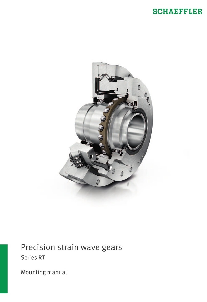
Schaeffler
Schaeffler RT Series Mounting manual

