nystrom EJ-FLF140 User manual

1
©2020 Nystrom, I
nc.
Installation, Operation
+ Maintenance Manual
Seismic Fire Barrier Expansion Joint System
Model(s): EJ-FLF140/EJ-FLW140
GENERAL DESCRIPTION
Expansion Joint Systems are an important life safety requirement
in current building codes. These systems allow safe movement
when buildings shift due to expansion and contraction.
The following are general instructions for installing, operating and
maintaining Expansion Joint Systems.
INSTALLATION
Preparation
Please read the complete instructions carefully before beginning any work. To ensure proper
installation and performance of the expansion joint system the following actions must be
completed by the installing contractor. Failure to do so will affect product warranty.
oInspect all shipments and materials for missing or damaged components and hardware.
oVerify joint width in field prior to ordering system. Minimum joint width of 2 inches
(51mm).
oVerify the structural gap and blockout dimensions are in conformance with submittal data
before beginning installation. Certification of this product was completed by Intertek
Testing laboratories. Product must be installed in accordance with these Installation
Instructions.
oEnsure joint is plumb and square, also verify soundness of substrate. Repair any spalls or
cracks prior to proceeding.
oFor vertical (wall) conditions, single-sided and double-sided blankets are available. For
single-sided product, ensure drape of blanket faces “potential” threat” side of wall.
GENERAL SAFETY PRECAUTIONS Improper selection, installation, or use can cause personal injury or property damage.
It is solely the responsibility of the user, through its own analysis to select products suitable for their specific
application requirements, ensure they are properly maintained, and limit their use to its intended purpose. Follow
proper local, state and federal regulations for proper installation and operation requirements.

2
©2020 Nystrom, Inc.
REV 8/2020
Seismic Fire Barrier Expansion Joint System
Installation, Operation & Maintenance Model(s): EJ-FLF140/EJ-FLW140
oIf job site specific conditions exist, these general installation instructions do not take place
of an Engineering Evaluation if required. Any modifications made to the product without
documented manufacturing direction will void the warranty.
Installation
1. Remove product from packaging and identify both male and female
ends, figure 1. Straighten male end if required before installation
into expansion joint.
It is best practice to install all horizontal blankets at each floor
continuously with no interruptions. Complete install with verticals.
2. Before starting a run, cut the male end off of the blanket, figure 2.
3. With the male end at the starting point of the installation;
insert barrier into expansion joint. If starting at an
exterior wall, ensure the male end of the stick covers the
total wall depth, figure 3.
TIP: If joint width is smaller than the specified nominal
joint width, compress the sides of the blanket evenly using
a wood form and clamps. This will allow the blanket to
regain its “pill” shape.
Reference detail of joint condition to ensure fire barrier is installed at a depth that does not conflict
with any part of the expansion joint system above.
4. While holding the aluminum frame on one side, cut the zip ties starting on one end working towards
the other end, figure 3.
5. Continue installation by overlapping male side into
female side. Ensure the transition connection is snug
and free of gaps. Verify the seam overlaps fit tight, with
no visible gaps or holes, figure 4.
NOTE: Installing male to female sections is easier if the
female end of the previous barrier is raised out of the
expansion joint. Butt the male end into the female end
and install into the expansion joint.
Figure 1
Figure 2
Figure 3
Figure 4

3
©2020 Nystrom, Inc.
REV 8/2020
Seismic Fire Barrier Expansion Joint System
Installation, Operation & Maintenance Model(s): EJ-FLF140/EJ-FLW140
6. Cut the zip-ties for the current fire barrier and continue installation for the rest of the run, figure 4.
7. If field conditions require a stick to be cut short, measure the
required length from male end and cut the appropriate length,
figure 5.
8. If the removed section of fire barrier contains a spring, be sure to
remove that spring from the dropped section, and re-install to
provided slots in blanket that will be installed, figure 5.
NOTE: Maintain a maximum spring spacing of 18 inches (450mm).
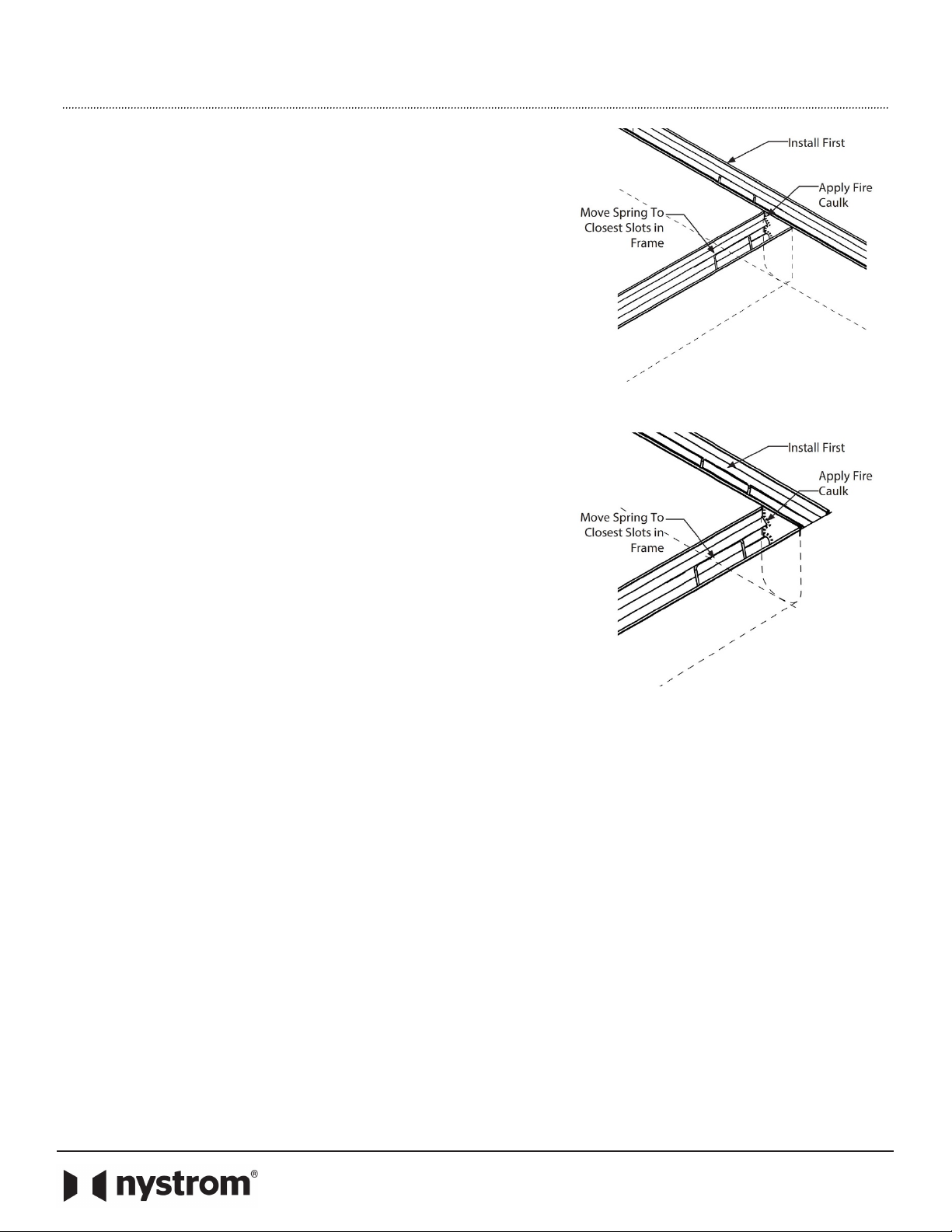
9. When the fire barrier meets a fire rated wall, continue the horizontal fire barrier uninterrupted, or a
minimum of the total wall depth to ensure no gaps exist at the intersections, figure 6. Reference figure
8.
10. If a spring of the horizontal fire barrier is located inside
the wall joint, it must be moved to a point before the
wall to achieve a proper transition. Maintain a maximum
spring spacing of 18 inches (450mm), figure 6.
11. Remove 2 inches (50mm) from each metal flange on the
male end of the barrier. Apply UL listed fire caulk liberally
to section of the fire horizontal barrier where the vertical
stick will intersect, face of the male end, flanges, and
interior walls of the slab before installing wall stick, figure
6. See figure 7 for more detail.
12. Insert fire barrier male end down and cut the bottom
most zip-tie and continue cutting upward, figure 6.
13. Continue vertical installation repeating steps 2-5 for the rest of the run, figure 7.
14. When intersecting horizontal barrier above, cut final piece to length, and trim female end to match the
drape of the horizontal barrier above, applying Fire Caulk to the under side of fire barrier, the portions
of the wall around the intersection, and inserting a female end. Ensure there are no gaps at transition,
figure 7.
15. For perpendicular installs, trim intersecting fire barrier, to match the pre-installed run. Apply fire caulk
to trimmed face, and side of pre-installed fire barrier, figure 7.
Figure 5
Figure 6

4
©2020 Nystrom, Inc.
REV 8/2020
Seismic Fire Barrier Expansion Joint System
Installation, Operation & Maintenance Model(s): EJ-FLF140/EJ-FLW140
16. Install continuous run before installing intersecting run, figure 9.
17. Before installing the intersection. Cut the intersecting end of the assembly to achieve a clean butt end,
figure 9.
18. Reposition the springs so that they are in the nearest spring slot to the cut end of the blanket, figure 9.
19. Insert the intersecting blanket into the expansion joint. Ensure the cut end of the fire barrier system
butts flush with the side wall of the intersecting system, figure 9.
Figure 8
Figure 7

5
©2020 Nystrom, Inc.
REV 8/2020
Seismic Fire Barrier Expansion Joint System
Installation, Operation & Maintenance Model(s): EJ-FLF140/EJ-FLW140
20. Apply fire caulk to seam at all visible openings, figure 9.
NOTE: Nystrom provides 1 or 2 tubes of fire caulk
(depending on order size) at no charge. Should additional
caulk be required, due to project or site complexity,
additional caulk to be provided by others.
OPERATION
Expansion Joints are designed and built for years of dependable service.
MAINTENANCE
oAnnual inspections should be performed to make sure the system is still in position. Repair
and/or replace as needed.
QUESTIONS?
For more information on installation, repair or replacement, please visit www.Nystrom.com.
Figure 9
This manual suits for next models
1
Table of contents
Other nystrom Industrial Equipment manuals
Popular Industrial Equipment manuals by other brands

Global
Global WF 1767-70 Series Instruction & parts manual

ABB
ABB HT563798 Operation manual

REXROTH
REXROTH HAB Assembly and Repair Instructions

AL-KO
AL-KO AKS 3004 operating instructions

Spirax Sarco
Spirax Sarco UTD30 Series Installation and maintenance instructions

Hyundai power products
Hyundai power products HYC5030 user manual