Image Engineering CAL3-XL User manual

Image Engineering GmbH & Co. KG · Im Gleisdreieck 5 · 50169 Kerpen-Horrem · Germany
T +49 2273 99991-0 · F +49 2273 99991-10 ·www.image-engineering.com
CAL3-XL
User Manual
26. February 2019

Image Engineering Error! Use the Home tab to apply Titel to the text that you want to appear here.
Seite 2von 11
Content
1INTRODUCTION............................................................................................................. 3
1.1 Conformity ................................................................................................................ 3
1.2 Intended use............................................................................................................. 3
1.2.1 Departing from described setup ......................................................................... 3
1.2.2 USB connection ................................................................................................. 3
1.3 General Safety Information ....................................................................................... 4
2GETTING STARTED....................................................................................................... 4
2.1 Scope of delivery ...................................................................................................... 4
3OPERATING INSTRUCTIONS HARDWARE.................................................................. 5
3.1 Overview display....................................................................................................... 5
3.2 Connecting the hardware.......................................................................................... 6
3.3 Camera positioning................................................................................................... 6
3.4 Using the included 4-prong alignment aid ................................................................. 8
3.5 Measurement precautions......................................................................................... 8
4OPERATING INSTRUCTIONS SOFTWARE .................................................................. 9
4.1 Requirements............................................................................................................ 9
4.2 Software installation.................................................................................................. 9
4.3 Starting the system ................................................................................................... 9
4.3.1 Spectrometer settings ........................................................................................ 9
4.3.2 iQ-LED calibration.............................................................................................. 9
4.4 Low intensity use .....................................................................................................10
5ADDITIONAL INFORMATION .......................................................................................10
5.1 Maintenance ............................................................................................................10
5.2 Care instructions......................................................................................................11
5.3 Disposal instructions................................................................................................11
6TECHNICAL DATA SHEET...........................................................................................11

Error! Use the Home tab to apply Überschrift 1 to the text that you want to
appear here.
Image Engineering Error! Use the Home tab to apply Titel to the text that you want to appear here.
Seite 3von 11
1 INTRODUCTION
Important information: Read the manual carefully before using the device.
Inappropriate utilization may cause damages to the device, to the DUT (device under test)
and/or other components of your setup.
Keep these instructions in a safe place and pass them to any future user.
1.1 Conformity
We, Image Engineering GmbH & Co. KG, hereby declare, that the CAL3-XL corresponds to the
essential requirements of the following EC directive in its current version:
•Electromagnetic Compatibility - 2014/30/EU
•RoHS 2 - 2011/65/EU
•Low Voltage - 2014/35/EU
1.2 Intended use
The CAL3-XL is designed as a calibration light source, based on iQ-LED technology for
cameras with a wide field of view. It includes a micro spectrometer and is controlled with the iQ-
LED control software or via dip switches on the device when not connected to a PC.
•Only suitable for indoor use.
•Place your system in a dry and constant tempered environment without any interfering
light.
•The optimal ambient temperature range is 22 to 26 degrees Celsius. The maximum
ambient temperature range is 18 to 28 degrees Celsius. If the system temperature gets
higher than 38 degrees Celsius, please check your ambient temperature.
•The optimal system temperature range, displayed in the software user interface, is
between 32 and 38 degrees Celsius. The system has internal temperature
management. If there is any error regarding the internal temperature, you will get a
warning message and the system will automatically shut down to avoid any damage.
1.2.1 Departing from described setup
The following steps must be performed in the correct chronology to allow frictionless
commissioning. Departing from the chronology may lead to an incorrectly working device.
1. Install the iQ-LED software
2. Connect CAL3-XL to the power and then via USB to the PC
3. Switch CAL3-XL on; the system drivers will now be installed
4. Start the software after drivers are installed completely
1.2.2 USB connection
Only appropriate USB connection allows error-free operation of CAL3-XL. Use the delivered
USB cables. If you need to extend the USB connection to longer distances, please check if
powered hubs/repeaters are necessary.
Error! Use the Home tab to apply Überschrift 1 to the text that you want to
appear here.
Image Engineering Error! Use the Home tab to apply Titel to the text that you want to appear here.
Seite 4von 11
1.3 General Safety Information
WARNING!
Some LEDs are emitting invisible light in the IR and UV near area.
•Do not look directly into the emitted light or look through the optical LED system.
•Do not look directly in the open sphere or light source when using high intensities
or sequences with low response time.
•Do not open the device without any instructions from the Image Engineering
support team or when connected to the power supply.
2 GETTING STARTED
2.1 Scope of delivery
•CAL3-XL
•spectrometer (built-in)
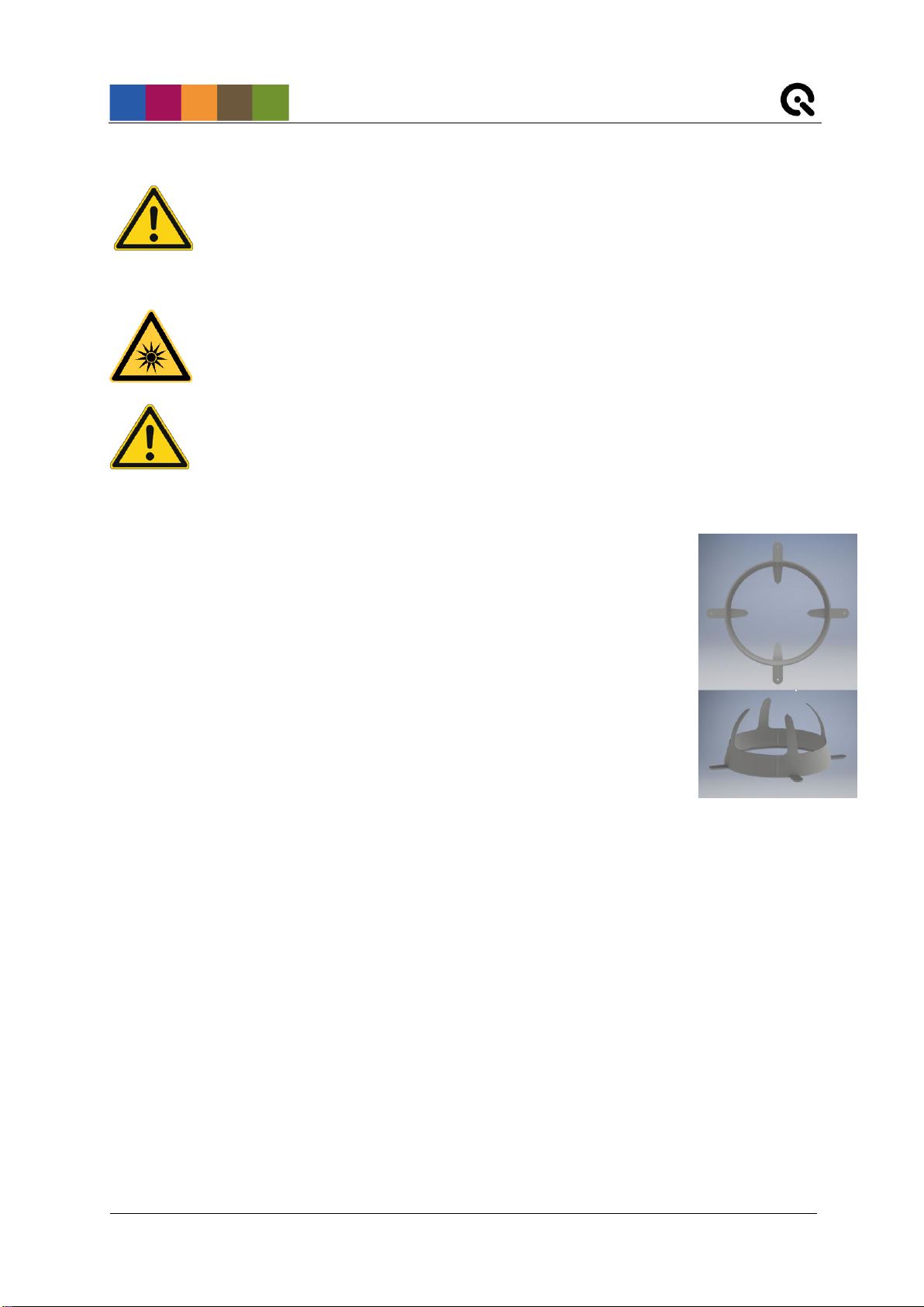
•4-prong removable alignment aid
•power cord
•USB cable
•control software
•calibration protocol
Optional equipment:
•Available soon: iQ-Align-XL for CAL3-XL for a quick and easy camera alignment.
•EX2 spectrometer for external measurments.
•iQ-Analyzer software (shading module)
This module includes a special chart layout file that allows analysis of images with and
without a keyhole effect.
Figure 1: 4-prong
alignment aid for CAL3-XL

Error! Use the Home tab to apply Überschrift 1 to the text that you want to
appear here.
Image Engineering Error! Use the Home tab to apply Titel to the text that you want to appear here.
Seite 5von 11
Figure 2: Control panel of CAL3-XL
3 OPERATING INSTRUCTIONS HARDWARE
3.1 Overview display
•1 x USB port for software control
•1 x port for power adapter
Use the control panel to set different light settings for the iQ-LED´s:
•with the “+” and “-“ buttons you can switch between up to 44 saved illuminants
•numerical display to show the storage number of the illuminants
•with the play and stop button you can start and stop a saved light sequence with
different illuminants (it is possible to save one sequence on the device)
•with the power button (0 / I), you can turn on and off the light (default illuminant)
•there are three pre-stored illuminants on your device (the intensity of each illuminant is
shown in the acceptance protocol of your device):
o1: illuminant A (default illuminant)
o2: illuminant D50
o3: illuminant D75
Note: To store your own generated illuminants or sequences on your device, please follow the
instructions in the iQ-LED SW user manual.

Error! Use the Home tab to apply Überschrift 1 to the text that you want to
appear here.
Image Engineering Error! Use the Home tab to apply Titel to the text that you want to appear here.
Seite 6von 11
3.2 Connecting the hardware
1. Connect the power cord to the power supply on the back of CAL-3XL.
2. Connect the USB cable to the CAL3-XL and your PC.
3. Turn on the CAL3-XL; the power switch is located beside the power supply.
4. Connect the spectrometer to the PC using the USB cable. The system will install the
spectrometer and the iQ-LED drivers on your PC, this will take a few seconds.
5. You can check the installation in your hardware manager.
Figure 3: Hardware Manager: active iQ-LED and spectrometer
3.3 Camera positioning
Requirements on your camera (device under test, DUT):
•maximum device diameter inside diffuser: between 100 and 150 mm
•lens depth inside diffuser (see Figure 4: positioning of DUT in front of CAL3-XL):
recommended: 75 mm1
minimum: 65 mm
maximum: 85 mm
Ensure that
•the lens is exactly in the center of the diffusor and it is not tilted
•the front end of the lens is ideally positioned at a depth of 65-85 mm inside the diffusor
•the angle of view of the lens does not exceed 180°
•if you are doing multiple measurements and need comparable results, the camera
needs to be positioned at the exact same location and in the same orientation
throughout the measurements to avoid deviating results.
Not fulfilling these requirements will lead to an inhomogeneously illuminated field of view and a
uniformity of less than 90%. The easiest way to align the camera correctly is to use the included
4-prong alignment aid (see 3.4) and the optional, soon to be available, iQ-Align-XL.
1A depth of 75 mm has been determined as the optimum to ensure the highest uniformity for fisheye cameras with an angle of
view of about 180°. This depth will be indicated by the included 4-prong alignment aid. For wide angle cameras with an angle of
view smaller than 180°, please see chapter 3.4 “Using the included 4-prong alignment aid”.

Error! Use the Home tab to apply Überschrift 1 to the text that you want to
appear here.
Image Engineering Error! Use the Home tab to apply Titel to the text that you want to appear here.
Seite 7von 11
Figure 4: positioning of DUT in front of CAL3-XL

Error! Use the Home tab to apply Überschrift 1 to the text that you want to
appear here.
Image Engineering Error! Use the Home tab to apply Titel to the text that you want to appear here.
Seite 8von 11
3.4 Using the included 4-prong alignment aid
The 4-prong alignment aid can be used to set up the DUT (Device Under Test) at the optimal
depth inside the diffuser to ensure uniformity of above 90% for your measurements. Steps 1 - 5
(Figure 5) illustrate the process and how to position the DUT. The camera in this example uses
a circular fisheye lens with an angle of view of 180°. The lens, not the CAL3-XL creates the
visible keyhole effect.
Step 1
Step 2
Step 3
Step 4
Step 5
Figure 5: Using the 4-prong alignment aid
Image 1 shows the removable alignment aid mounted on the CAL3-XL from the DUT’s point of
view. Images 2 through 5 show the DUT moving closer to the optimal depth inside the diffuser.
In image 5 you can see, illustrated by the red dotted lines, that the correct depth is reached as
soon as the four prongs have completely left the frame captured by the DUT. This process
works both for circular and non-circular fisheye lenses and it does not depend on the angle of
view of the DUT. What does, however, depend on the angle of view is the necessary depth
inside the diffuser to fulfill these criteria. Devices with an angle of view smaller than 180° do not
need to be positioned as deep inside the diffusor as devices with an angle of view of 180°.
In case your DUT uses a non-circular fisheye lens that reaches its maximum angle of view
diagonally, it becomes necessary to rotate the device around its optical axis so that the four
prongs are as close to the edges of the frame as possible.
3.5 Measurement precautions
Ensure the device under test is completely encased in a black housing with only the lens
uncovered. If it is not, we advice covering it with a black, non-reflective fabric such as Molton.
Covering the DUT will ensure that light from the CAL3-XL will not reflect off the DUT (especially
colored devices) and back onto the diffuser and distort the test results.

Error! Use the Home tab to apply Überschrift 1 to the text that you want to
appear here.
Image Engineering Error! Use the Home tab to apply Titel to the text that you want to appear here.
Seite 9von 11
4 OPERATING INSTRUCTIONS SOFTWARE
4.1 Requirements
•PC with Windows 7 (or higher) operating system
•one free USB port
4.2 Software installation
Install the iQ-LED control software before connecting the hardware. Follow the setup
instructions from the iQ-LED control software manual.
4.3 Starting the system
Start the iQ-LED software by clicking the ‘iQ-LED.exe’ or the iQ-LED icon on your desktop.
Follow the iQ-LED software manual to control the CAL3-XL.
NOTE
The iQ-LED devices can only operate with high precision, when setup and calibration
are performed correctly.
Consult the iQ-LED software manual for a comprehensive description and read it
carefully.
4.3.1 Spectrometer settings
The iQ-LED software (see iQ-LED software manual) automatically generates the best
spectrometer settings for you lighting conditions after pressing the “auto detect” button. For
special applications, it is also possible to set the spectrometer settings manually. If you have
further questions, please contact the Image Engineering support team.
4.3.2 iQ-LED calibration
The individual LED lights of the iQ-LED inside the CAL3-XL depend on many different types and
wavelengths. Some LEDs will change their intensity level and peak wavelength slightly in the
first 500-600 working hours because of a burn-in effect.
The LEDs will also degrade in intensity during their lifetime. To make sure that all
measurements including the auto-generated illuminants and the standard illuminants are
correct, you have to perform a spectral calibration regularly.
You must also consider the degradation of the LEDs when saving self-defined presets. If you
save a preset with LED channels that uses its maximum intensity, the possibility exists that this

Error! Use the Home tab to apply Überschrift 1 to the text that you want to
appear here.
Image Engineering Error! Use the Home tab to apply Titel to the text that you want to appear here.
Seite10 von11
intensity cannot be reached after the burn-in time or the long-time degradation of the LEDs. In
this case, you will get a warning message from the iQ-LED control software.
During the first 500-600 working hours, we recommend performing a spectral calibration every
50 operating hours.
After the first 500-600 operating hours, a calibration of every 150 working hours suffices.
Factors that indicate the need for a spectral calibration: unsatisfactory illuminant generation, the
aberration of the intensity values, or a spectral curve that does not fit with the predefined
standard illuminants of the corresponding preset.
If you run into problems when generating illuminants, please check if…
•the spectrometer works correctly
•the spectrometer settings are correct
•all LED channels work correctly
•the dark measurement is correct
•your measurement environment is correct
•your ambient temperature is correct
How to perform the spectral calibration is described in the iQ-LED control software manual.
4.4 Low intensity use
When using your system with very low intensity, the spectral measurement values will start to
fluctuate. The lower the intensity, the higher the fluctuation. The generated light is still stable up
to a certain point. The fluctuation of the values is caused by the noise of the spectral
measurement of the internal spectrometer. The light intensity will continue to get lower when the
influence of the noise continues to get higher. When using standard illuminants with an intensity
lower than 25 lux, it will no longer be possible to get a correct value.
5 ADDITIONAL INFORMATION
5.1 Maintenance
Your spectrometer comes fully NIST traceable calibrated. The spectrometer requires a
recalibration once a year, regardless of the operating hours. If a spectrometer calibration is
necessary, please contact Image Engineering. We will provide you with removal instructions for
the spectrometer. The spectrometer then has to be sent to our office with a notation for
calibration. Use appropriate packaging to prevent the spectromter from being damaged during
shipping.
A temporary replacement spectrometer can be provided to bridge the time gap while your
spectrometer is recalibrated. Please contact us for conditions and procedure.

Error! Use the Home tab to apply Überschrift 1 to the text that you want to
appear here.
Image Engineering Error! Use the Home tab to apply Titel to the text that you want to appear here.
Seite11 von11
5.2 Care instructions
•Do not touch, scratch, or pollute the diffusor.
•If there is any dust on the diffusor, clean it with an air blower.
•Do not remove the fiber from the spectrometer. Otherwise, the calibration is invalid, and
the spectrometer has to be recalibrated!
•Only store and transport the CAL3-XL in the delivered hard case.
5.3 Disposal instructions
After the service life of CAL3-XL, it must be disposed of properly. Electrical and
electromechanical components are included in CAL3-XL. Observe your national regulations.
Make sure that CAL3-XL cannot be used by third parties after disposing of it.
Contact Image Engineering if assistance for disposal is required.
6 TECHNICAL DATA SHEET
See annex for the technical data sheet. It can also be downloaded from the website of Image
Engineering: www.image-engineering.com.
Other manuals for CAL3-XL
1
Table of contents
Other Image Engineering Industrial Equipment manuals

Popular Industrial Equipment manuals by other brands


Bühler technologies
Bühler technologies GAS 222.11 Ex2 Installation & operation instructions

Siemens
Siemens SINUMERIK Equipment manual

Montanari
Montanari M73ES Directions for installation, use and maintenance

PHD
PHD GRF DESIGN 2 Series REPAIR PROCEDURES

Magpowr
Magpowr DFC-90 instruction manual

RSP
RSP TC250-8 product manual


