Diamatic BDC 1115-P User manual
The Choice of Professionals
www.diamatic.usa info@diamatic.usa
Operating Instructions
BDC 1115-P
Original Operating Instructions
Version 1.0
Diamatic
622 Grant Rd
Folcroft, PA 19032
Tel: +1 619-295-0893

The Choice of Professionals
www.diamatic.usa P a g e | 2 info@diamatic.usa
Table of Contents
1.Introduction ---------------------------------------------------------------------------------------------------------------------------3
2.Machine Description ----------------------------------------------------------------------------------------------------------------4
3.Safety------------------------------------------------------------------------------------------------------------------------------------5
General Safety Warnings:---------------------------------------------------------------------------------------------------------5
1115-P Instructions, Grounding Instructions: -------------------------------------------------------------------------------5
Grounding Check --------------------------------------------------------------------------------------------------------------------5
4.Engine Emissions and CO Safety--------------------------------------------------------------------------------------------------6
Potential Effects of CO Exposure -----------------------------------------------------------------------------------------------6
Methods to Reduce the Risks of CO Poisoning -----------------------------------------------------------------------------6
Potential Effects of CO Exposure -----------------------------------------------------------------------------------------------7
Methods to Reduce the Risks of CO Poisoning -----------------------------------------------------------------------------8
4.1 Work Area Safety ------------------------------------------------------------------------------------------------------------ 13
4.2 Personal Safety --------------------------------------------------------------------------------------------------------------- 13
4.3 Machine Safety General----------------------------------------------------------------------------------------------------14
4.4 Maintenance Safety --------------------------------------------------------------------------------------------------------- 14
4.5 Safety Regarding DustCollectors ---------------------------------------------------------------------------------------- 14
4.6 Transport Safety-------------------------------------------------------------------------------------------------------------- 15
5.Initial Operations-------------------------------------------------------------------------------------------------------------------15
5.1 Checkpoints of Electrical Safety------------------------------------------------------------------------------------------ 15
5.2 Checkpoints of Machine Safety ------------------------------------------------------------------------------------------ 15
5.3 Pretreatment of Filters -----------------------------------------------------------------------------------------------------15
6. Tool Tips for BMG-1115-P -------------------------------------------------------------------------------------------------------16
6.1 Start Up ------------------------------------------------------------------------------------------------------------------------- 16
6.2 Shut Down --------------------------------------------------------------------------------------------------------------------- 16
7.Start Up:------------------------------------------------------------------------------------------------------------------------------ 17
7.1 Standard Filter Inspection: ------------------------------------------------------------------------------------------------ 17
8.Inspection and Maintenance----------------------------------------------------------------------------------------------------- 18
8.1 Standard Filter Inspection: ------------------------------------------------------------------------------------------------ 18
8.2 Standard Filter Replacement Instructions:---------------------------------------------------------------------------- 19
8.3 HEPA Maintenance: ---------------------------------------------------------------------------------------------------------20
8.4 Belt Inspection: --------------------------------------------------------------------------------------------------------------- 21
8.5 Belt Replacement: -----------------------------------------------------------------------------------------------------------21
8.6 Belt Tensioner:---------------------------------------------------------------------------------------------------------------- 22
8.7 Pully Alignment:-------------------------------------------------------------------------------------------------------------- 23
8.8 Turbine Replacement: ------------------------------------------------------------------------------------------------------23
9.Troubleshooting --------------------------------------------------------------------------------------------------------------------24
10.Technical Information----------------------------------------------------------------------------------------------------------- 25
11.Electrical Schematic--------------------------------------------------------------------------------------------------------------26
12. Warranty----------------------------------------------------------------------------------------------------------------- 28

The Choice of Professionals
www.diamatic.usa P a g e | 3 info@diamatic.usa
1. Introduction
Before use, operators must be provided with information, instruction and training for the use of the machine and the
substances for which it is to be used, including the safe method of removal and disposal of the material collected. All persons
who are working with or maintaining this machine must read the manual carefully and understand it fully. In case you sell
the unit, hand it on to the next owner.
Keep this manual always with the machine, to enable it to be referred to at any time. Any other
work not covered by this operating manual must not be carried out.
This machine is designed for industrial use by professionals. Only authorized and trained personnel may operate this
machine. This machine is not intended for use by persons (including children) with reduced physical, sensory or mental
capabilities, or lack of experience and knowledge. Diamatic USA offers a course on the use of the machine in order to make
the operating and maintenance personnel familiar with all elements of the machine.
The Choice of Professionals
www.diamatic.usa P a g e | 4 info@diamatic.usa
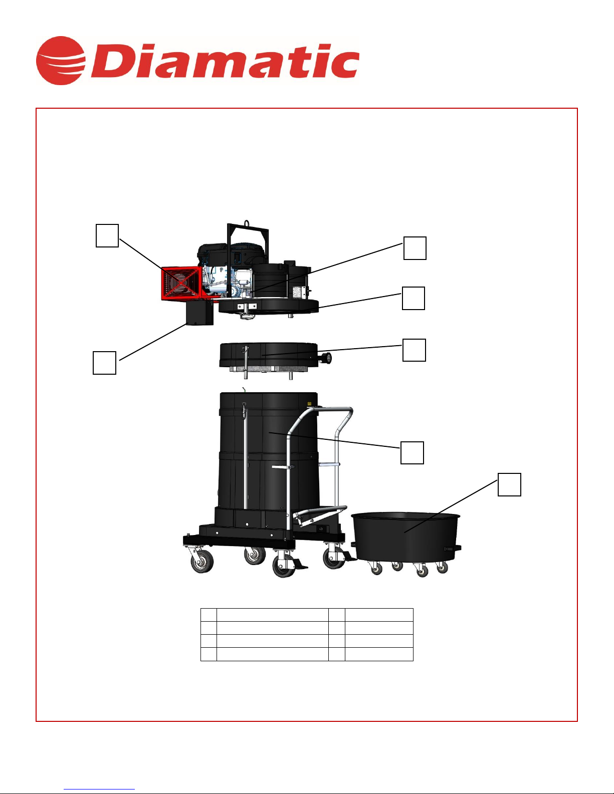
2. Machine Description
The BMG- 1115-P is a propane powered dust collector that provides a dust free environment when attached to a Diamatic
grinder or burnisher in dry grinding applications only. Utilizing microclean filtration, the 1115-P can achieve 99% efficiency at
0.5 microns. The 1115-P will produce up to 630 CFM and can run 7-8 hours on a single 33lb propane tank. Included on the 1115-
P is a detachable dust pan fitted for 24 gallons. Using the 1115-P ensures a dust free environment that provides clean air to the
workspace.
1
20 HP Propane Engine
2
Engine Deck
3
Filter Ring
4
Frame
5
Dust Bin
6
12V Battery
7
Muffler Guard
8
-------------
2
1
1
3
4
5
6
7

The Choice of Professionals
www.diamatic.usa P a g e | 5 info@diamatic.usa
3. Safety
General Safety Warnings:
a. CAUTION: Standard DIAMATIC 1115-P machines are not to be used for the removal of liquids or any volatile,
viscous, flammable or explosive media. If you are unsure about your application requirements consult your
DIAMATIC representative.
b. CAUTION: Standard DIAMATIC 1115-P machines are designed for continuous use, provided the vacuum is not
held under constant stress. If you are unsure about your application requirements consult your DIAMATIC
representative.
c. CAUTION: The components in this machine can be very heavy. Always follow safe lifting procedures.
d. CAUTION: A dust mask should be worn when working with fine materials.
e. CAUTION: Check motor direction. Vacuum can be produced while operating in both directions. A backwards
rotation will produce 40% less while heating the bearings, however. The motor should always run clockwise.
f. CAUTION: Vacuums are not design for working in classified explosion atmospheres in accordance to OSHA /
NFPA regulations.
1115-P Instructions, Grounding Instructions:
This appliance must be grounded. If it should malfunction or breakdown, grounding provides a path
of least resistance for electrical current to reduce the risk of electric shock.
Grounding Check
•ABOUT DIAMATIC’S 1115-P AND GROUND:
oAll 1115-P are constructed of carbon impregnated fiberglass housings which dissipate static charge
oMetal components are electrically grounded through a series of internal ground wires. Grounding can be confirmed
using a standard multimeter
Note: If continuity is not found across any of these points, consult the parts manual to check that all ground wires are in
place. For further assistance, contact DIAMATIC.
Check for continuity
between the batter and
handle bar, dustpan
lever, and starter box if
applicable.
Also check for continuity
between the battery and
inlet, all four casters and
frame hardware if
applicable.

The Choice of Professionals
www.diamatic.usa P a g e | 6 info@diamatic.usa
4. Engine Emissions and CO Safety
The information provided in the following overview has been condensed to provide the reader with a summary of the material
presented.
Potential Effects of CO Exposure
•
Work place/industry guidelines for CO exposure limits vary substantially from region to region (OSHA)
Permissible Exposure Limit (PEL) for CO is 50 ppm, as an 8-hour time weighted average.
•
Definition of CO effects - The toxic effects of carbon monoxide in the blood are the result of tissue hypoxia (lack of
oxygen). The severity depends on the state of activity of the individual and his tissue oxygen needs.
Methods to Reduce the Risks of CO Poisoning
•
Air Exchange and CO Diffusion - CO does not mix with air on its own. Air currents can “stir” the CO and dilute the
concentration values by mixing it with the available air. When using equipment over a large area in a short time “stirring”
occurs as you walk.
•
Application Considerations (Burnishing versus Stripping) - When activity is concentrated to a smaller area as in a
stripping application, air “stirring” must be forced using fans to reduce the risk of high concentrations of CO.
•
Air Quality Monitoring –Deployment of a monitor/detector is essential for the safe operation of any equipment that
has the potential to produce CO.
•
Room Size and Time Estimations - The concentration and volume of CO production, the size of the area and the
amount of air exchange are factors involved with determining safe time limits for operation in a specific room size.
•
Maintenance of Equipment - LPG engines are dependent on engine tune up, and air filter replacement. CO concentration
(production) skyrockets when the air to fuel ratio becomes fuel rich. Follow the recommended Maintenance Schedule for
the engine.
•
Safety Equipment Available. - Automated fuel to air ratio monitoring and regulation providing an optimum combustion,
three-way type catalytic converter to scrub CO, Hydro Carbons (HC), and Nitrous Oxide (NOx) from the engine exhaust
providing the lowest possible emissions, high cubic feet per minute (CFM) fans (forced air mixing), and digital combustion
analyzers for tail pipe emissions monitoring.

The Choice of Professionals
www.diamatic.usa P a g e | 7 info@diamatic.usa
Potential Effects of CO Exposure
·
Work place/industry guidelines for CO exposure limits
·
Definitionof COeffects
Work place/industry guidelines for CO exposure limits
Limits for permissible exposure to CO vary substantially from region to region. City, State, and Industry requirements
should be consulted prior to use of any equipment.
The current Occupational Safety and Health Administration (OSHA) Permissible Exposure Limit (PEL) for CO is 50 ppm, as an
8-hour time weighted average (TWA). This is computed by making measurements at intervals over 8 hours, then adding the
sums of the concentrations and the intervals, and dividing by 8 hours. For example:
Time
Interval
PPM
8:00-9:00
1 HR
100
9:00-10:00
1 HR
25
10:00-11:00
1 HR
25
11:00-12:00
1 HR
50
12:00-1:00
1 HR
50
400ppm/8HR=50ppm TWA
1:00-2:00
1 HR
50
2:00-3:00
1 HR
50
3:00-4:00
1 HR
50
Time intervals =
8 HR
ppm =
400
The current National Institute for Occupational Health and Safety (NIOSH), immediately dangerous to life and health
concentration (IDLH) recommended level for CO is 1,200 ppm. NIOSH defines the IDLH exposure level as the concentration
that could result in irreversible health effects or death, or prevent escape from the contaminated environment within 30 minutes.
Definition of CO Effects
The toxic effects of carbon monoxide in the blood are the result of tissue hypoxia (lack of oxygen). carbon monoxide combines
with hemoglobin to form carboxyhemoglobin. Since CO and oxygen react with the same group in the hemoglobin molecule,
carboxyhemoglobin is incapable of carrying Oxygen. The affinity ofhemoglobin for CO is200 to 240 times greater than for
oxygen. The extent of saturation of hemoglobin with CO depends on the concentration of the gas, the quantity of inspired air
and on the time of exposure. The severity depends on the state of activity of the individual and his tissue oxygen needs.
According to Harrison’s Principles of Internal Medicine 7th edition, no symptoms will develop at a concentration of 0.01% CO
(100ppm) in inspired air, since this will not raise blood saturation above 10 %. Exposure to 0.05% (500ppm) for 1 hour during
light activity will produce a blood concentration of 20% carboxyhemoglobin and result in a mild or throbbing headache. Greater
activity or longer exposure causes a blood saturation of 30 to 50 %. At this point head ache, irritability, confusion, dizziness,
visual disturbance, nausea, vomiting, and fainting can be experienced. Exposure for one hour to concentrations of 0.1%
(1000ppm) in inspired air the blood will contain 50 to 80% carboxyhemoglobin which results in coma, convulsions, respiratory
failure and death. On inhalation of high concentrations of CO, saturation of the blood proceeds so rapidly that unconsciousness
may occur suddenly without warning.

The Choice of Professionals
www.diamatic.usa P a g e | 8 info@diamatic.usa
Methods to Reduce the Risks of CO Poisoning
•AirExchangeandCODiffusion
•Application Considerations (Burnishing versus Stripping)
•Air QualityMonitoring
•RoomSizeandTimeEstimations
•Maintenance ofEquipment
•SafetyEquipmentAvailable
Air Exchange and CO Diffusion
The most reliable method to prevent CO Poisoning is to ensure all the CO produced is vented outside. With wood stoves or gas
heaters this is performed with ductwork that carries the exhaust and CO outside. Non-stationary combustion type equipment
must be used in such a way that CO is not allowed to rise to a harmful or dangerous level.
CO does not readily dissipate or mix with air on its own. Air currents can “stir” the CO and dilute the concentration or ppm
values by mixing it with the available air. When using equipment over a large area in a short time “stirring” occurs as you walk,
or to say it another way, your Effective Operating Zone is large. When activity is concentrated to a smaller area as in a stripping
application, the Effective Operating Zone is small, and “stirring” must be forced using fans to increase the Effective Operating
Zone and reduce high concentrations of CO.
Air exchange rates (air exchange is defined as the exhausting of internal air to the external atmosphere), the size of the
Effective Operating Zone, amount of CO produced, level of human activity, and the duration of exposure are all factors in the
determination of the production of carboxyhemoglobin and the amount of CO blood saturation.
Application considerations (Burnishing versus Stripping)
When using equipment over a large area in a short time, as in most burnishing applications, your Effective Operating Zone is
large. When activity is concentrated to a smaller area as in stripping applications, the Effective Operating Zone is small and
stirring or CO mixing MUST be forced using fans to increase the Effective Operating Zone and reduce high concentrations of
CO.
Caution: air mixing may not be sufficient to reduce CO to a safe level. The Effective
Operating Zone can be defined as the area covered in a given time.
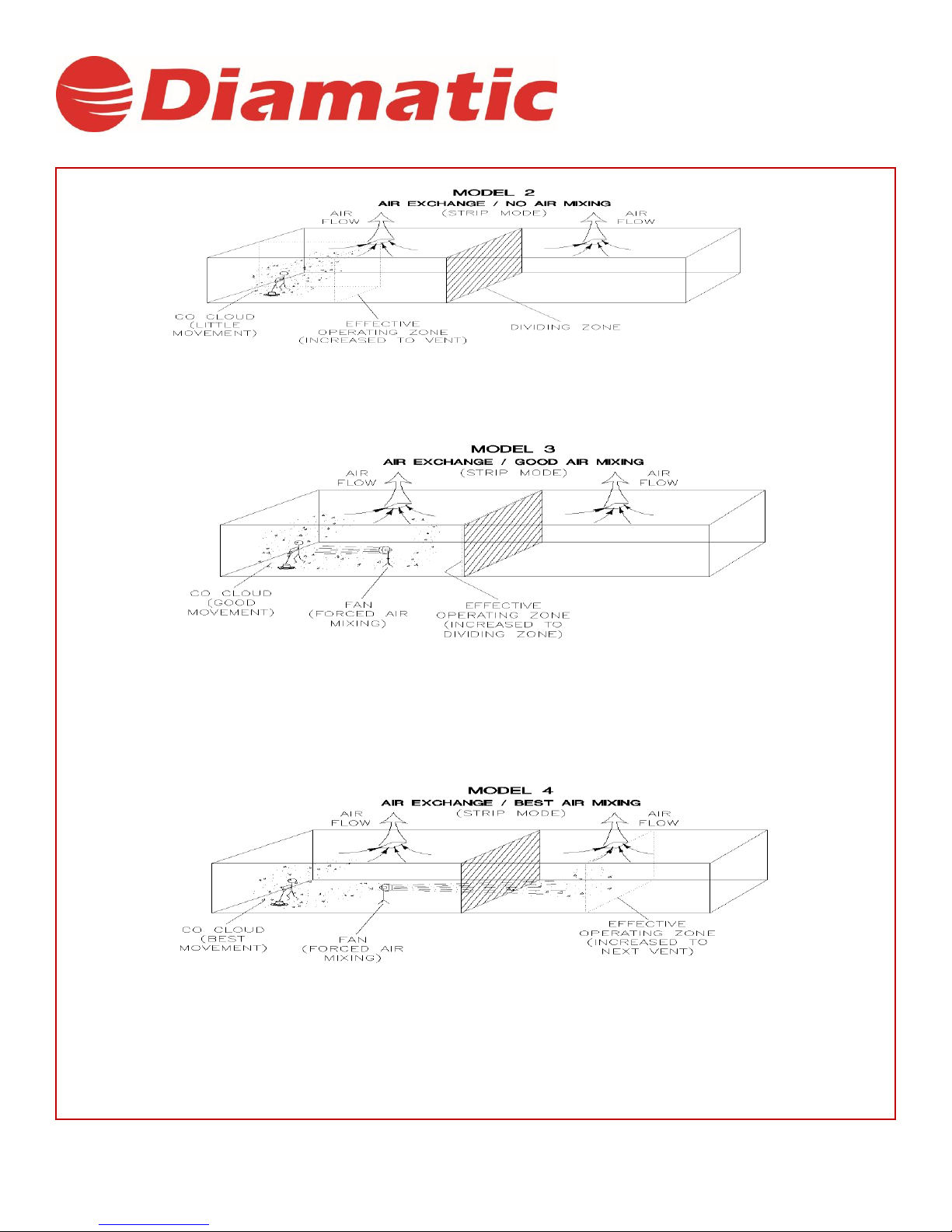
Stripping is quite a different type of operation than burnishing, and carries with it substantially more hazards, as stripping is a low
movement operation compared to burnishing (less floor space for the same time). As shown in Model 1, the CO concentrations
rise much quicker as the “Effective Operating Zone” is a very small area compared to the total building size.
The Choice of Professionals
www.diamatic.usa P a g e | 9 info@diamatic.usa
Notice the CO concentration and the Effective Operating Zone with air exchange. The CO cloud is still concentrated in a small
area. Note the “Dividing Zone” shown above, this is the line where airflow changes direction. In Model 2, air changes are cut in
½ as little or no CO crosses the Dividing Zone to be exhausted.
Notice the CO concentration and the Effective Operating Zone (Expanded to the Dividing zone) with air ex- change and forced
air mixing. The CO cloud is still concentrated on one side of the Dividing zone. Note the “Dividing Zone” shown above, thisisthe
line where airflow changes direction. InModel 3, air changes are cut in ½ as little or no CO crosses the Dividing Zone to be
exhausted.
Notice the CO concentration and the Effective Operating Zone (Expanded through the Dividing zone to the second vent) with air
exchange and forced air mixing through the dividing Zone. The CO cloud is diluted with the available air in the
building. Note the “Dividing Zone” shown above, this is the line where airflow changes direction. In Model 4, air changes are
full as forced air mixing has moved and mixed the CO between all air zones.
The Choice of Professionals
Air Quality Monitoring
Warning: Deployment of a monitor/detector is essential for the safe operation of any equipment that has the potential to
produce CO. CO sensors/detectors became available on the mass market around 1978. At present several brands sell in the
fifty-dollar range. The main differences between the technologies involved are battery or electric and Semiconductor or
Biomimetic types. Detectors for carbon monoxide (CO) are manufactured and marketed for use in either the home or
occupational industrial settings. The detectors for home use are devices that will sound an alarm before CO concentrations in
the home become hazardous. There is an Underwriters Laboratories, Inc., performance standard (UL 2034) for residential CO
detectors. Detectors currently available on the market are battery-powered, plug- in, or hard-wired. Some models incorporate a
visual display of the parts per million (ppm) concentration of CO present in the home. For more information on CO detectors for
home use, call the Consumer Product Safety Commission Hotline at 1-800-638-2772.
CO detectors for use in residential settings are not designed for use in typical workplace settings. Monitoring requirements in an
occupational setting are different from monitoring requirements in the home. In the workplace, it is frequently necessary to
monitor a worker’s exposure to carbon monoxide over an entire work shift and determine the time-weighted average (TWA)
concentration of the exposure. It may also be necessary to have carbon monoxide monitors with alarm capabilities in the
workplace. The direct-reading instruments are frequently equipped with audio and/or visual alarms and may be used for area
and/or personal exposure monitoring. Some have microprocessors and memory for storing CO concentration readings taken
during the day. It is significant to note that some of the devices mentioned for workplace CO monitoring are not capable of
monitoring TWAs, and not all are equipped with alarms. The appropriate monitor must be chosen on an application-by-
application basis. For more information on the availability of workplace CO monitors or their application, call the National
Institute for Occupational Safety and Health at 1-800-35- NIOSH(1-800-356-4674).
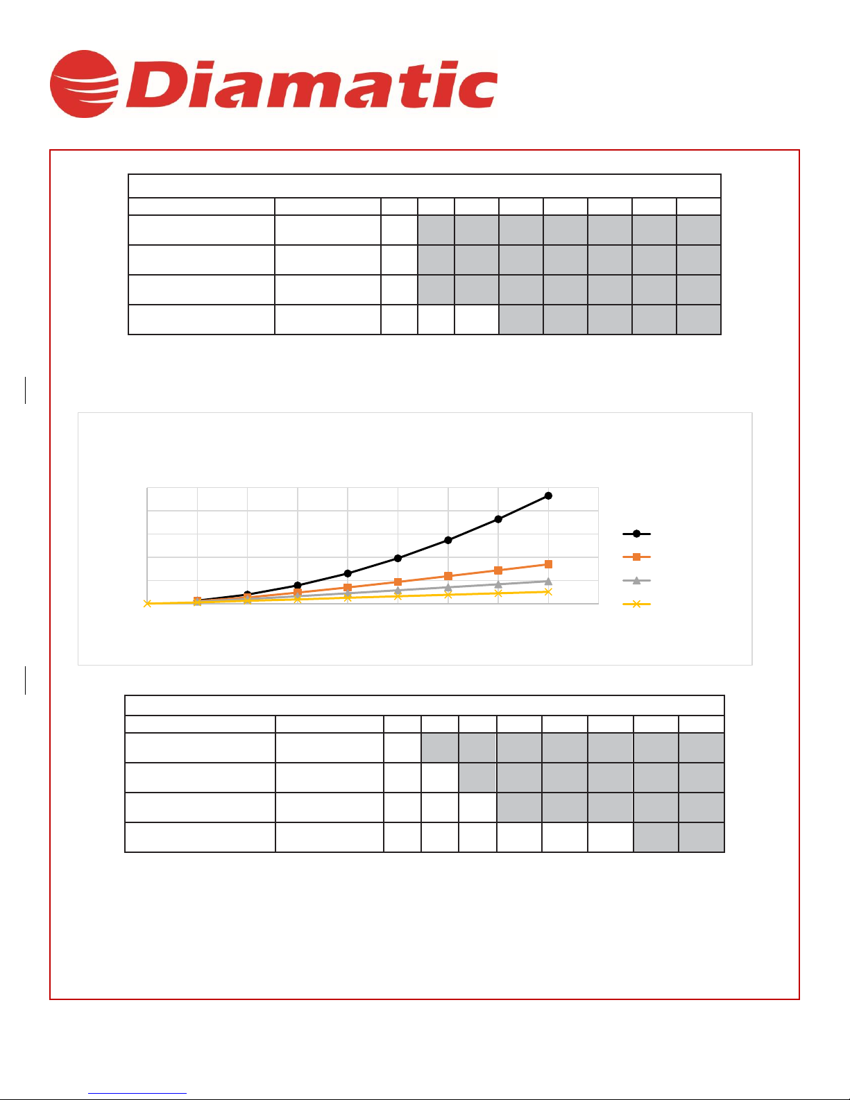
Room Size and Time Estimations for Parts Per Million (PPM) CO
The fundamental factors in area CO levels involve: The
concentration and volume of CO production; The size of the
area;
The amount of *air exchange if any; The amount of
time CO is produced.
Multiplying length, width, and height will determine the volume or cubic feet in a room. So, an empty building 100ft by 100ft
with a 10ft ceiling would be 100,000 cubic ft. in size. Any material that is in the room and takes space would reduce the cubic
feet.
*Air exchange is defined as the exhausting of internal air to the external atmosphere.
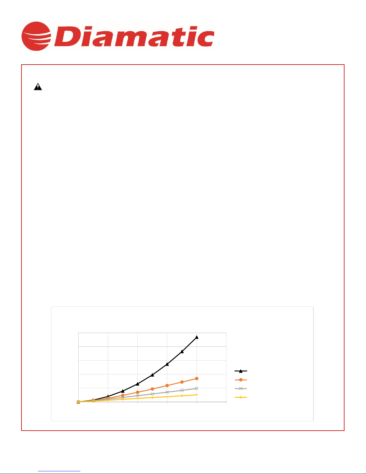
ThegraphbelowdepictstherelationshipsofairexchangetotimeandCOppmwithcubicfeetareaandpercentCO emissions
remainingconstant
0
200
400
600
800
1000
0 2 4 6 8 10
PPM
Time (Hours)
1.14 % CO Emission in 100,000 cubic feet with 656cc Engine and
complete air/CO mixing
0.0 change/hour
0.5 change/hour
1.0 change/hour
2.0 change/hour
The Choice of Professionals
8 Hour Time Weighted Average (OSHA Method)
1.14% CO 100,000cf
Hours Operation
1
2
3
4
5
6
7
8
TWA (OSHA Method)
0 change/hr.
25.84
78.28
156.56
260.68
390.64
546.44
728.84
936.32
1/2 change/hr
20.52
53.2
94.24
139.08
186.96
236.36
287.28
338.2
1 change/hr
16.72
38.76
63.84
89.68
115.52
141.36
167.2
193.8
2 change/hr
11.4
24.32
37.24
50.16
63.08
76
88.92
102.6
Based on the CO production rates shown above the TWA would be exceeded in a 100 x 100 x 10 foot (empty) space after 3 hours with 2
air changes per hour. (Assumes no additional CO exposure during 8 hour time period.
8 Hour Time Weighted Average (OSHA Method)
1.14% CO 500,000cf
Hours Operation
1
2
3
4
5
6
7
8
TWA (OSHA Method)
0 change/hr
12.92
38.76
78.28
129.96
195.32
273.6
364.04
465.12
1/2 change/hr
10.64
26.6
47.12
69.92
93.48
118.56
143.64
169.48
1 change/hr
8.36
19.76
31.92
44.84
57.76
70.68
83.6
96.52
2 change/hr
5.32
12.16
18.24
25.08
31.92
38
44.84
50.92
Based on the CO production rates shown above the TWA would be exceeded in a 100 x 500 x 10 foot (empty) space after 6 hours with 2
air changes per hour. (Assumes no additional CO exposure during 8 hour time period)
0
100
200
300
400
500
0 1 2 3 4 5 6 7 8 9
PPM
Time (hours)
1.14% CO Emission in 500,000 cubic feet with 656cc Engine and
complete air/CO mixing
0.0 Change/hour
0.5 Change/hour
1.0 Change/hour
2.0 Change/hour

The Choice of Professionals
ThegraphabovedepictstherelationshipsofairexchangetotimeandCOppmwithcubicfeetareaandpercentCO emissionsremaining
constant.
8 Hour Time Weighted Average (OSHA Method)
1.14% 750,000cf
Hours Operation
1
2
3
4
5
6
7
8
TWA (OSHA Method)
0 change/hr
3.8
10.64
20.52
34.96
52.44
72.96
97.28
124.64
1/2 change/hr
3.04
6.84
12.16
18.24
25.08
31.92
38
44.84
1 change/hr
2.28
5.32
8.36
12.16
15.2
19
22.04
25.84
2 change/hr
1.52
3.04
5.32
6.84
8.36
9.88
12.16
13.68
Based on the CO production rates shown above the TWA would not be exceeded in a 100x750x 10 foot (empty) space
after 8 hours with 2air changes perhour.(Assumes no additional CO exposure during8 hourperiod)
Maintenance of Equipment
Warning: The proper maintenance of equipment is vital to safe operation. LPG engines are dependent on engine tune up, and
air filter replacement. CO concentration (production) skyrockets when the air to fuel ratio becomes fuel rich. Follow the
recommended Maintenance Schedule for the engine found in the Engine Operator/Owner Manual as well as the Maintenance
and Adjustments schedule found in the Propane Floor Equipment Operator’s Manual that were supplied with the equipment.
CO Safety Equipment Available
•Automated emissions monitoring will shut down the engine when high emissions are detected.
•Three-way type catalytic converter to scrub CO, Hydro Carbons (HC), and Nitrous Oxide (NOx) from the engine
exhaust providing the lowest possible emissions
•High cubic feet per minute (CFM) fans (forced air mixing)
•Digital combustion analyzers for tail pipe emissions monitoring
0
20
40
60
80
100
120
140
0246810
PPM
Time (hours)
1.14% CO Emission in 750,000 cubic feet with 656cc Engine
and complete air/CO mixing
0.0 Changes/hour
0.5 Changes/hour
1.0 Changes/hour
2.0 Changes/hour

The Choice of Professionals
4.1 Work Area Safety
a)
Do not use the machine in rain, damp or wetlocations.
b)
Avoid dangerous environments: do not work in the presence of explosive atmospheres, in the presence of flammable
liquids, gases or dust. Remove materials or debris that may be ignited bysparks.
c)
In some cases, sparks could be created bygrinding.
d)
The surface to be treated must be clean, make sure to remove all stones, screwsetc...
Any stones, screws, bolts, pieces of wire etc. could cause serious damage if it gets inside the machine!
e)
Make sure there is enough ambient light on the work area. Cluttered or dark areas inviteaccidents.
f)
Do not use on wood.
g)
Keep children and bystanders away while operating the machine. They are likely not to foresee the potential
dangers of the machine. Distractions could cause you to lose control of the machine.
h)
Persons who are not operating the machine must not be permitted to stay in the surrounding area of at least 5 meters
from the machine.
i)
Never use the machine when the surface is not clear and if there is a risk of stumbling ortripping.
j)
Make sure that there are no cables or hoses in the driving direction of themachine.
k)
Make sure that there is nothing standing or situated on the surface to betreated.
l)
Make sure the machine can travel over all inequalities on the surface, small inequalities like weld seams or floor joints
are not barriers for themachine.
m)
Never stay in the rain with the machine.
n)
Check if there are any obstacles that can snag the cables when the machine ismoving.
o)
Remove reinforcing steel or other objects protruding from the surface to prevent damage to the compounds or diamond
discs.
p)
Warning!
Make sure that the surface to be treated does not contain dangerous materials such as:
-
combustible or explosive dusts orsubstances.
-
carcinogenic or pathogenicsubstances.
q)
Secure the work area around the machine in public areas providing an adequate safety distancefrom the machine. Use
a red and white safety chain and danger sign to enclose the workarea.
4.2 Personal Safety
a)
Always wear Personal Protective Equipment while working with themachine.
-Dust mask class FFP2 or higher
-Ear protection
-Safety glasses with lateral protection
-Protecting gloves
-Safety shoes
b)
Dress properly. Do not wear loose clothing or jewelry. Keep your hair, clothing and gloves away from moving parts.
c)
Stay alert, watch what you are doing and use common sense when operating themachine.
d)
All persons in the proximity of the machine, must wear eye/ear protection and safetyshoes.
e)
Always seek professional medical attention immediately in case ofinjury.

The Choice of Professionals
4.3 Machine Safety General
a)
Safety functions and operating functions must workcorrect.
b)
No loose bolts and nuts permitted.
c)
Never operate machine without the guards and/or safety devices inplace.
d)
Never change anything on the safety devices on themachine!
e)
The machine, specially the handle grips must be free of fats/oils and must be dry.
f)
If the length of the brushes is, due to wear, less than 5mm or they are extremely deformed, the brushes must be
replaced. Check the Service Manual for the ordernumbers.
g)
All repair work must be done by qualified Diamatic personnel, this guarantees a safe and reliable machine.
h)
Always use original Diamatic spare parts, grinding disks, grinding wings and polishing pads. This will ensure the
best performance. Only original Diamatic parts meet the factory specifications and quality. Otherwise Diamatic BV
cannot guarantee the safety of themachine.
The part numbers can be found in the Service Manual.
i)
Check the rotating direction of the motor. The correct direction is given with an arrow on the housing of the motor.
j)
If safety-critical changes occur to the machine or its working method, the machine must beshut down
immediately! The cause of the fault must be established, andrectified.
k)
In the event of operational malfunctions, the machine must be shut down immediately and secured!
l)
Do not use the unit when it is damaged.
m)
Do not open or remove protective guards while driving gears arerunning.
4.4 Maintenance Safety
a)
Press the e-stop and turn the ignition key off before starting inspections and repairing on themachine.
b)
Wait for standstill of all drives before any inspections, adjustments and/or maintenance work is started.
c)
Block the machine in a stable position before doing any maintenancework.
d)
Failures due to inadequate or incorrect maintenance may generate very high repair costs and long standstill periods
of the machine. Regular maintenance therefore isimperative.
e)
Operational safety and service life of the machine depends, among other things, on proper maintenance. Prevent
premature wear by keeping the machine as dust free as possible. Clean the machine regularly with a dust collector and
non-aggressive materials, especially the engine. Never use a high-pressure water cleaner to clean themachine.
f)
It is advisable to stock all spare parts or wear parts that cannot be supplied quickly. As a rule, production
standstill periods are more expensive than the cost for the corresponding sparepart.
g)
Do not use any aggressive cleaningmaterials!
h)
Use lint-free cleaningcloths!
i)
For the electrical parts, use a tool that is insulated againstvoltages
4.5 Safety Regarding DustCollectors
a)
If equipped with vacuum shroud, always use a Diamatic dust collector (when working dry) to ensure a dust-free
operation of themachine and clean air at the workspace. Also, the airflow helps to cool the machine and prevents
overheating.
b)
Read the operating instructions of the dust collector before usingit.
c)
The dust container/bag of the dust collector must be emptied regularly. Comply with the local waste treatment
regulations considering the removedmaterial.
d)
The dust hose must be connected properly with a hose clamp and industrialtape.
e)
The dust hose must be undamaged and free ofobstructions.
f)
Always switch on the dust collector first!

The Choice of Professionals
4.6 Transport Safety
a)
Be aware of your surroundings and machine operating level. Do not use on a side hill, do not run on steep incline, this could
cause machine to tip over.
b)
The weight of the 1115-P is 521 lbs. Use a crane or lift when transporting the machine, use the lifting eyes of the machine.
c)
When transporting the machine do so in such a manner that damage from the use of force or incorrect loading and unloading is
avoided.
d)
Always drive backwards when driving up to a ramp or grade, and forwards when driving off the ramp
e)
Chock wheels for transport and keep control handle in neutralposition.
f)
Don’t leave the machine unsecured on jobsites.
g)
Always park the machine on a flat horizontal and level surface.
h)
If equipped, make sure the floating shroud is in transport mode when you transport themachine.
i)
Store the cleaned and dry machine in a humid free room. Protect the engine from moisture, heat and dust
j)
Never use the machine for lifting or transporting persons or items.
5. Initial Operations
Before using the machine, it is important to inspect the machine.
It is not permitted to use the machine if the machine safety is not according the checkpoints below. Before switching on
the machine make sure that no-one can be endangered when the machine starts up!
5.1 Checkpoints of Electrical Safety
a) Check all electrical connections for tightness.
b) Check wiring harness for cuts and abrasions.
c) No damage is permitted for wiring harness.
d) Check battery hold down strap is secure. Tighten if necessary
5.2 Checkpoints of Machine Safety
a) Safety functions and operating functions must workcorrect.
b) Check the tooling for damages and/orwear.
c) Check all screws and other fasteners for tightness. No loose bolts and/or nuts arepermitted.
d) Check the electrical components, cables and connections for wear and/ordamages.
e) If equipped with dust shroud, dust hose connection must be reliable: use hose clamps and industrialtape.
f) Dust hoses must be undamaged and free ofobstructions
5.3 Pretreatment of Filters
All New machines sold from DIAMATIC or one of its featured distributors come pretreated with Sodium Potassium
Aluminum Silicate (NaKAlSiO4). The off-white powder is used to pretreat the filters by filling the micron sized holes in the filter.
By pre-filling the filters before actual use, the filters will work more efficiently and the filter will last longer. This pretreatment
results in a more efficient machine and less maintenance of the machine over time.
Note: This pretreatment will cover the inside of the machine making it look like dust has been ran through the system. What is
inside the machine is not dust particles from grinding and burnishing but the NaKAlSiO4. Please refer to
The Choice of Professionals
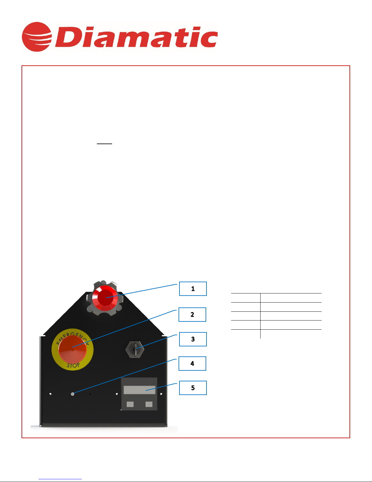
6. Tool Tips for BMG-1115-P
6.1 Start Up
•Wear correct PPE including; steel toe boots, CO monitor, gloves, eye and hearing protection.
•No loose-fitting clothing or Jewelry. Make sure work area is well ventilated.
•Check engine oil. Add if below the fill line. Do not overfill.
•With safety key removed and E-stop engaged. Tilt machine back and install diamond tooling. Make sure mating
surfaces are clean of dirt and debris. Once installed, slowly lower machine back to work surface.
•Install properly filled vapor propane tank and ensure hose coupler is secure. 99% of all propane related issues are
from improperly/overfilled tanks.
•Turn tank valve counter clockwise to open valve and supply fuel.
•Ensure safety key is installed in deadman control and attach lanyard to your wrist or belt loop.
•Ensure Ignition switch is in the off position, the E-stop is disengaged and the throttle is pushed all the way down to
idle position.
•Turn the ignition switch clockwise one click to the run position. Wait for red emission control light to go out for
Kawasaki engine or turn green for Briggs and Stratton engine.
•Turn the ignition clockwise to engage the starter. Once engine fires and runs let go of ignition switch. Let engine
idle for 1 minute. Engine will idle at 1480-1520RPM when warm
6.2 Shut Down
•Turn throttle lock counter clockwise.
•Depress red button and push throttle cable down until is stops at idle (1480-1520 rpm).
•Turn the propane bottle valve clockwise and shut off fuel. Let the engine run out of fuel and shut down. Please note
the exhaust and engine will have hot surfaces.
•Depress E-Stop switch and turn ignition switch to off position.
•To re- start engine, follow steps above in the startup section.
Item No.
Operational Parts
1
Throttle Cable
2
Emergency Stop
3
Ignition Switch
4
Emission Control Light
5
Tachometer
The Choice of Professionals
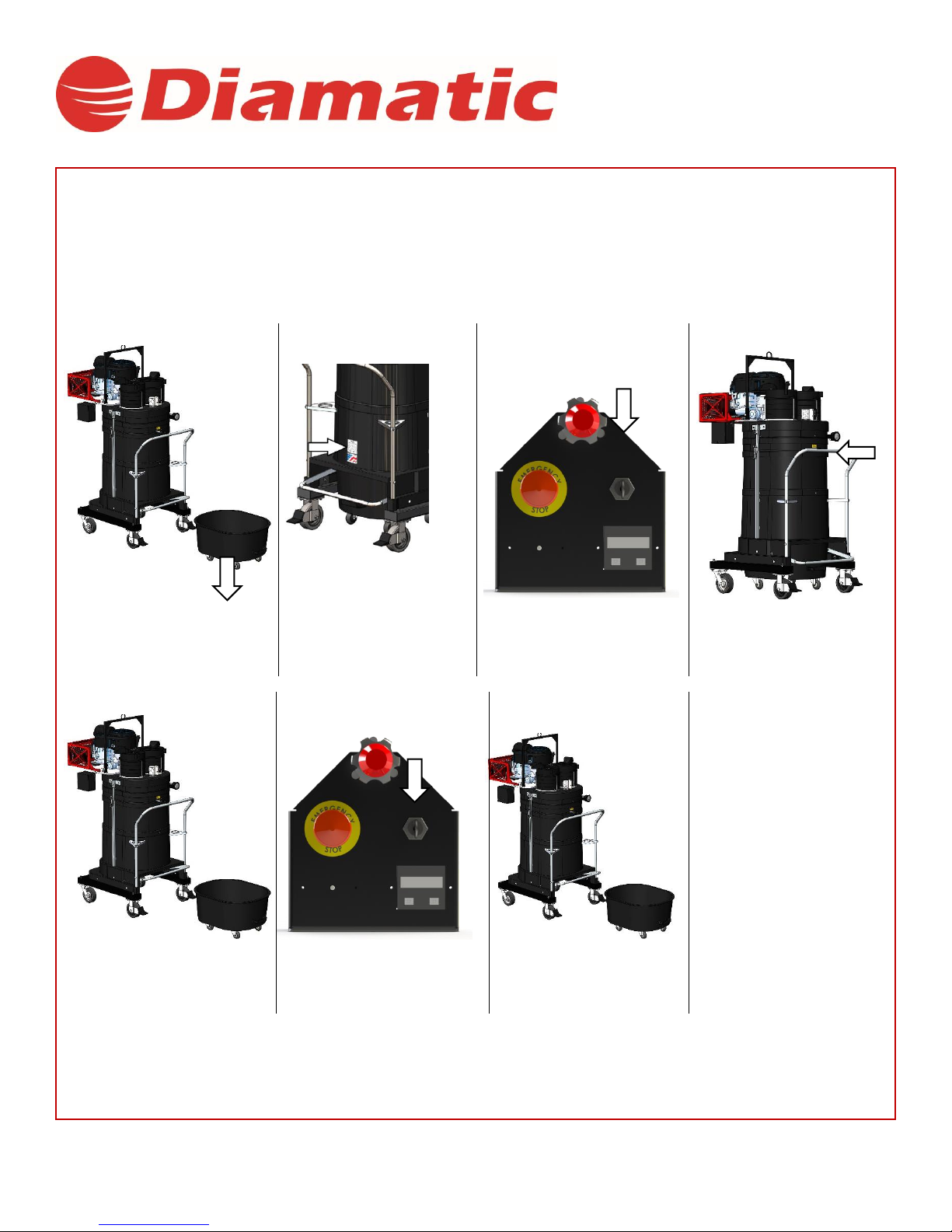
7. Start Up:
7.1 Standard Filter Inspection:
WARNING: Always wear a dust mask when performing filter inspections or service.
1
2
3
4
Pull up on the dustpan lever
to release the dustpan. Check
that the dustpan is empty,
then replace it.
Connect the machine to
proper power source, as
indicated by the serial tag.
Quickly turn the motor on then
off to confirm the motor
direction.
Use the filter shaker to clean
the filter before and after each
use.
5
6
7
Empty the dustpan by
releasing the rear lever.
Turn on the motor before
removing the dustpan. This
will ensure excess material
sticks to the filter.
Remove dustpan and empty
contents.
Dustpan should be emptied
after every use.
The Choice of Professionals
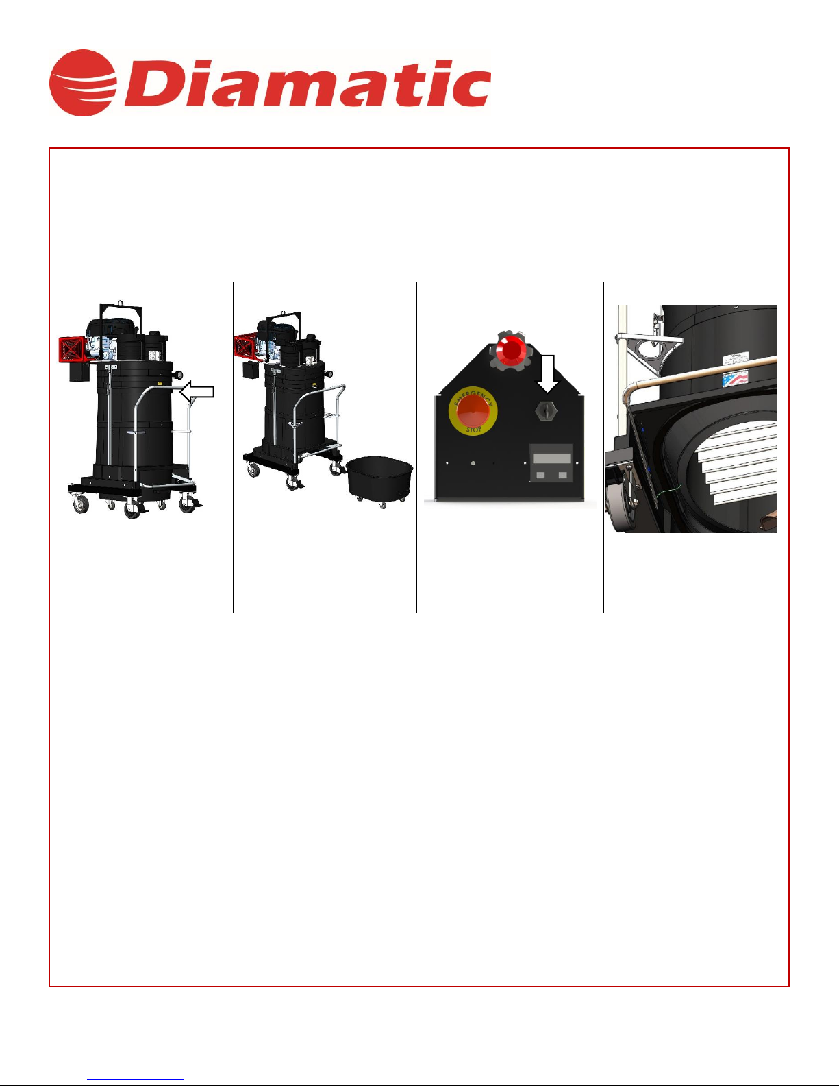
8. Inspection and Maintenance
8.1 Standard Filter Inspection:
CAUTION: Refer to OSHA / NFPA guidelines regarding handling of your material prior to servicing filter. Always follow proper
safety procedures when working with hazardous materials.
1
2
3
4
Use the shaker bar to clean
the filter while the machine
is off.
Remove the dustpan.
Turn the machine on
to trap excess material
against the filter.
Look underneath the base to
inspect the filter. Check the
inlet for wear.
Note: Using an object to dislodge material may tear the filter. Consult your DIAMATIC representative if material blockage is
excessive. Do not use high pressure compressed air or water to clean off filter, as material may become permanently lodged into
filter membrane.
The Choice of Professionals
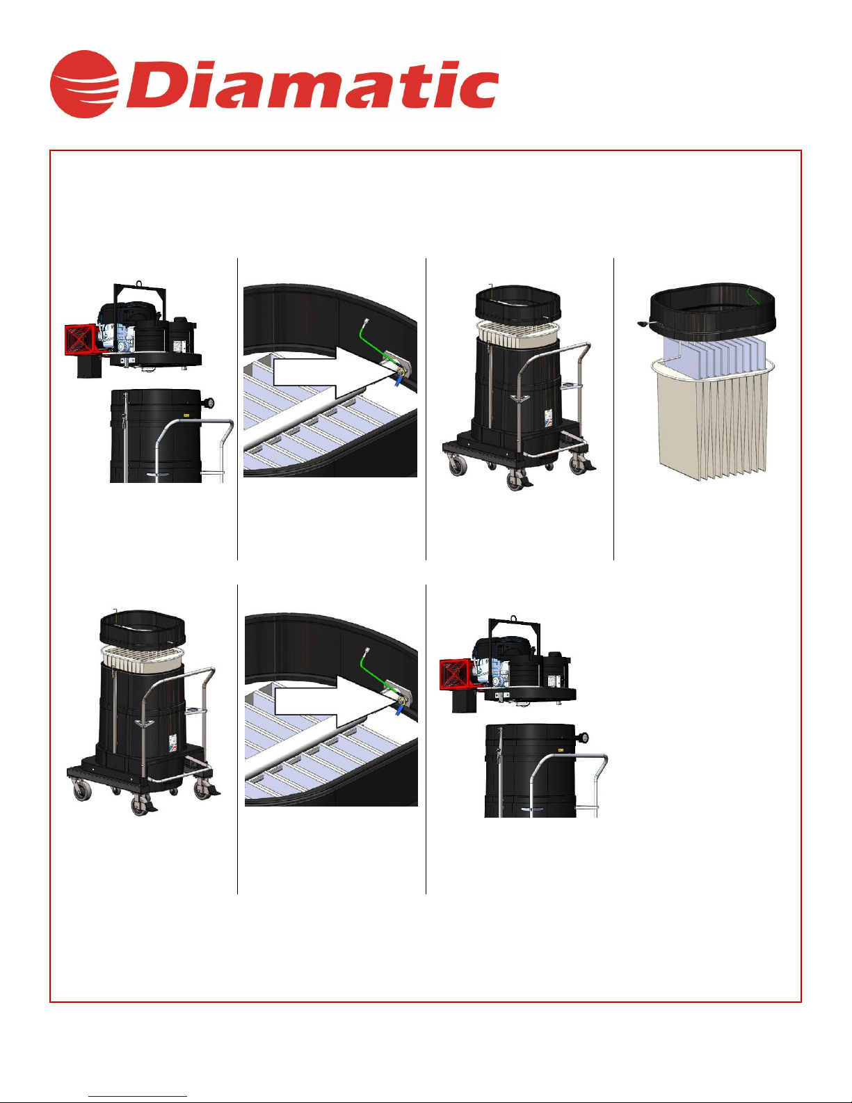
8.2 Standard Filter Replacement Instructions:
CAUTION: Motor deck will be heavy and will require a crane to remove. Always wear a dust mask when performing filter
inspections or service.
1
2
3
4
Remove the motordeck
using a hoist.
Disconnect the filter
ring grounds.
Lift the filter ring and
remove the filter from
cage.
Replace the filter over
the cage. Be sure to
place the filter inserts
into the pleats.
5
6
7
Place the filter ring
back onto the base.
Be sure that the filter is
seated properly.
Reconnect the ground wires.
Replace the motordeck and
clamp it together.
NOTE: The presence of material above the filter or in the exhaust is often the result of a misaligned seal or damaged filter. Consult
your DIAMATIC representative if either is the case.

The Choice of Professionals
8.3 HEPA Maintenance:
CAUTION: Motor deck will be heavy and will require a crane to remove.
1
2
3
4
To ensure optimal
performance, replace the
filterat8”W.C.
Release the clamps and
remove the motordeck using a
hoist
Disconnect the ground wires.
Locate and loosen the
bracket hardware.
5
6
7
8
Remove and replace
the filter.
Secure the bracket hardware.
Reconnect all ground wires.
Replace motordeck and fasten
the clamps.
Table of contents
Other Diamatic Industrial Equipment manuals

Popular Industrial Equipment manuals by other brands

Zimmer
Zimmer MATCH LWR50F-09-03-A Installation and operating instructions

Virutex
Virutex PB83E operating instructions

Toro
Toro LAC TM installation guide

Grundfos
Grundfos Polydos 412E Installation and operating instructions

Alpha Technologies
Alpha Technologies ALPHA OUTBACK ENERGY Cordex HP LPS04 Installation & operation manual

SMG
SMG Rapid-Edge 10H Operator's manual

Eaton
Eaton Airflex WCB Series Installation, operation and maintenance

Renishaw
Renishaw LP2 installation guide

Huaqi Zhengbang
Huaqi Zhengbang ZB3245TSS user manual

Tarana
Tarana 1101-1027-KT installation guide

GUDEL
GUDEL NRH Series Service manual

ZIEHL-ABEGG
ZIEHL-ABEGG ZA top SM200.15D Assembly instructions


