4 M0619-1 ver. 2.6
CONTENTS
1 INTRODUCTION......................................................................................................6
1.1 Safety.........................................................................................................................7
1.1.1 General...............................................................................................................................7
1.1.2 Explanation of warnings .....................................................................................................7
1.2 Description of RSP tool changers...............................................................................8
1.3 Complementary Equipment........................................................................................8
2 TECHNICAL SPECIFICATIONS..............................................................................9
2.1 Description of tool changers and tool attachments .....................................................9
2.1.1 Coordinate System Definition...........................................................................................10
2.1.2 Tool Changer with air, TC250-8. Article no: P6411..........................................................11
2.1.3 Tool Attachment, TA250-8. Article no: P6417..................................................................12
2.1.4 Square Tool Attachment TA250-8. Article no: P6474......................................................13
2.1.5 Tool Changer with air and electric signals TC250-8E. Article: P6412 .............................14
2.1.6 Tool Attachment, TA250-8E. Article no: P6418 ...............................................................16
2.1.7 Tool Attachment, TA250-8E. Article no: P6431 ...............................................................17
2.1.8 Square Tool Attachment, TA250-8E. Article no: P6473...................................................18
2.1.9 Pneumatic diagram for tool changers P6411 and P6412 ................................................19
2.1.10 Circuit diagram E0196-001 for P6412............................................................................20
2.1.11 Circuit diagram E0196-002 for P6418............................................................................21
2.1.12 Circuit diagram E0196-009 for P6431 and P6473 .........................................................22
2.2 Options to TC...........................................................................................................23
2.2.1 Robot adaptation kit .........................................................................................................23
2.2.2 Tool stand kit. Article no: P6472.......................................................................................24
2.2.3 Limitation of Robot movements........................................................................................24
2.2.4 Connection kits and cables ..............................................................................................24
3 INSTALLATION.....................................................................................................25
3.1 Tightening torques....................................................................................................25
3.2 Recommended tools for installation..........................................................................25
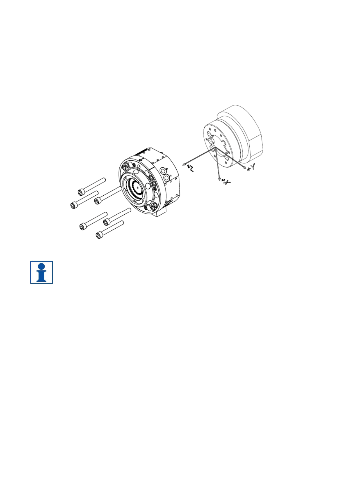
3.3 Installation of tool changer on robot..........................................................................26
3.4 Installation of tool attachment P6623A/ P6624A on tool ..........................................27
3.5 Hints.........................................................................................................................28
3.5.1 Programming....................................................................................................................28
3.5.2 Sparking ...........................................................................................................................28
3.5.3 Electrical installation.........................................................................................................28
3.5.4 Tool stand.........................................................................................................................28
3.5.5 Tool Identification .............................................................................................................28