Blacoh Sentry User manual
INSTALLATION & OPERATION MANUAL
DAMPENER
(CHARGEABLE MODEL)
SENTRY dampeners are pressure vessels containing a flexible bladder or bellows inside that separates
an inert pressurized gas (air or Nitrogen) from a system fluid in the lower chamber. Depending on how
dampeners are configured, they are used as PULSATION DAMPENERS, INLET STABILIZERS or SURGE
SUPPRESSORS to control pressure fluctuations and spikes in liquid piping systems.
Dampeners work on the principle that volume is inversely proportional to pressure (P1V1=P2V2).
Compressed air or Nitrogen (never Oxygen) is introduced into the non-wetted side of the dampener. The
gas charge is contained by the bladder or bellows preventing contact between the system fluid and the gas.
When the dampener is sized correctly, properly installed and charged according to the instructions
provided, it will greatly reduce the damaging effects of pressure variations in piping systems and
significantly improve the efficiency of transferring liquids.
All dampeners manufactured by BLACOH use pressure bodies made in the USA to insure quality.
Prior to shipment, each and every dampener is factory tested at design pressure or higher to assure
proper function and leak-free operation.
Foreign language versions available online at:
http://blacoh.com/literature/literature_instructions.aspx

1BLACOH FLUID CONTROL, INC.
TABLE OF CONTENTS
Model Specifications & Installation Information .................................................................................................1
SAFETY Warnings ...............................................................................................................................................2
Safety Symbols .......................................................................................................................................................... 2
General Safety ........................................................................................................................................................... 2
Equipment Misuse Hazard ......................................................................................................................................... 3
GENERAL Information .........................................................................................................................................3
Must Read Before Installation .................................................................................................................................... 3
Installation Notes........................................................................................................................................................ 4
ATEX Standard .......................................................................................................................................................... 4
Maintenance............................................................................................................................................................... 4
Temperature Limits .................................................................................................................................................... 5
Installation & Operation Instructions: Dampener (Chargeable Model) ...............................................................6
Pre-Charge Notes ...................................................................................................................................................... 6
Installation for Pump Discharge Pulsation.................................................................................................................. 6
Installation for Pump Inlet........................................................................................................................................... 7
Installation for Surge / Water Hammer ....................................................................................................................... 8
Manufacturer’s Limited Warranty & Return Policy............................................................................................10
MODEL SPECIFICATIONS & INSTALLATION INFORMATION
Model No. Serial No. Installation Date
/
Body Material: Wetted / Non-wetted Bladder/Bellows Material Pump Area and Number
Purchased From Contact Phone E-Mail
THE WORD “DAMPENER”, AS USED IN THIS MANUAL,HAS THE SAME MEANING AS PULSATION DAMPENER, INLET STABILIZER,
OR SURGE SUPPRESSOR.
Copyright © 2010 Blacoh Fluid Controls, Inc. All rights reserved.
Information in this document is subject to change without notice. No part of this publication may be reproduced, stored in a retrieval system or
transmitted in any form or by any means electronic or mechanical, including photocopying and recording for any purpose other than the
purchaser’s personal use without the express written permission of Blacoh Fluid Controls, Inc.

BLACOH FLUID CONTROL, INC.2
SAFETY WARNINGS
Dampeners should only be installed, operated and repaired by experienced and trained professional mechanics.
Read and observe all instructions and safety warnings in this Manual before installing, operating or repairing
dampeners.
SAFETY SYMBOLS
The following symbols indicate cautions, warnings and notes that must be observed for safe and satisfactory
installation, operation and maintenance of dampener.
WARNINGS Danger of serious injury or death could occur if these warnings are ignored.
CAUTIONS Equipment damage, injury or death could occur if these cautions are not observed.
NOTES Special instructions for safe and satisfactory installation, operation and maintenance.
GENERAL SAFETY
CAUTION!
Observe all safety symbols in installation and
operation instructions.
The internal dampener pressure will equal the
maximum fluid pressure of the system in which it
is installed.
DO NOT exceed maximum allowable working
pressure (MAWP) specified on dampener serial
tag or marked on dampener. If serial tag is
missing, DO NOT use dampener without
consulting distributor or factory for maximum
pressure rating.
Always make sure safety shutoff valves,
regulators, pressure relief valves, gauges, etc.
are working properly before starting system or
assembly.
Verify dampener model received against
purchase order and shipper.
Before starting a system or assembly make
certain the discharge point of the piping system is
clear and safe, and all persons have been warned
to stand clear.
DO NOT put your face or body near dampener
when the system or assembly is operating, or
dampener is pressurized.
DO NOT operate a dampener that is leaking,
damaged, corroded or otherwise unable to
contain internal fluid, air or gas pressure.
DO NOT pump incompatible fluids through
dampener. Consult distributor or factory if you
are not sure of the compatibility of system fluids
with dampener materials.
Dampeners are designed to operate with
compressed air or clean dry Nitrogen only. Other
compressed gases have not been tested and may
be unsafe to use. DO NOT USE OXYGEN.
Always shut off air supply, remove internal
dampener pressure, and shut dampener isolation
valve before performing dampener maintenance
or repair.
Remove all pressure from dampener AND
pumping system before disassembly, removal or
maintenance.
Static spark can cause an explosion resulting
in severe injury or death. Ground dampeners
and pumping system when pumping
flammable fluids or operating in flammable
environments.
NOTE: EC standard EN-13463-1 and EN-
13463-5 (ATEX) require grounding (earthing)
on dampeners when the potential for static
sparking is present. A grounding point is
located and marked on ATEX specific
dampener models.

3BLACOH FLUID CONTROL, INC.
EQUIPMENT MISUSE HAZARD
CAUTION!
General Safety
DO NOT misuse dampener, including but not limited
to over-pressurization, modification of parts, using
incompatible chemicals, or operating with worn or
damaged parts. DO NOT use any gases other than
compressed air or clean dry Nitrogen to charge
dampener. DO NOT USE OXYGEN. Any misuse
could result in serious bodily injury, death, fire,
explosion or property damage.
Over-Pressurization
Never exceed the maximum pressure rating for the
dampener model being used. Maximum allowable
working pressure (MAWP) is specified on dampener
serial tag or marked on dampener. Maximum
allowable working pressure (MAWP) is rated at 70°F
(21°C).
Temperature Limits
DO NOT exceed the operating temperature limits for
the body and/or elastomer materials being used.
Excessive temperature will result in dampener
failure. For temperature limits, refer to the
“Temperature Limits” section of the Manual.
Temperature limits are stated at zero psi/bar.
Installation and Start-Up Hazards
Install dampener before charging or pressurizing.
DO NOT start system or assembly without first
charging or pressurizing dampener. Failure to
charge may result in damage to the elastomeric
bladder or PTFE bellows.
Temperature & Pressure Hazard
Temperature and pressure reduce the strength and
chemical resistance of plastic, metal, elastomers and
PTFE.
Charging / Pressurization
Charge or pressurize dampener with compressed air
or clean dry Nitrogen only. DO NOT USE OXYGEN.
Dampener Bladder/Bellows Failure
Dampeners utilize an elastomeric membrane
(bladder) or PTFE bellows to separate system fluid
from the air supply or gas charge. When failure
occurs, system fluid may be expelled from the air
valve. Always perform preventive maintenance and
replace bladder/bellows before excessive wear
occurs. O-rings for PTFE bellows cannot be re-used.
Maintenance Hazards
Never over-tighten fasteners. This may cause
leakage of system fluid and damage to dampener
body. Bolts on metal models should not be reused
as re-torquing reduces bolt strength. AFTER
MAINTENANCE OR RE-ASSEMBLY OF METAL
MODELS, USE NEW FASTENERS AND TORQUE
FASTENERS ACCORDING TO SPECIFICATION ON
DAMPENER TAG.
GENERAL INFORMATION
For safe and satisfactory operation of dampener, read all safety warnings and caution statements, and
this complete Manual before installation, startup, operation or maintenance.
MUST READ BEFORE INSTALLATION
DO NOT use Oxygen to charge dampener.
Use compressed air or clean dry Nitrogen
only.
Danger of static spark! Grounding precautions
must be considered when dampener is used in
flammable or explosive environments.
DO NOT exceed maximum allowable working
pressure (MAWP) specified on dampener serial
tag or marked on dampener.
ATEX Models must be grounded (earthed)
before operation.
Turn pump off and remove all pressure from
system prior to dampener installation.
DO NOT operate a dampener that is leaking,
damaged, corroded or otherwise unable to
contain internal fluid, air or gas pressure.
Always wear safety glasses and other
appropriate safety equipment when installing,
charging or repairing dampener.
Temperature, pressure and chemicals affect the
strength of plastic, elastomer, and metal
components.
Many plastics lose strength rapidly as
temperature increases. Consult factory if in
doubt.
BLACOH FLUID CONTROL, INC.4
INSTALLATION NOTES
Dampening of flow pulsations can only be effective if 5 to 10 psi (0.4 to 0.7 bar) back pressure
downstream of dampener is available. A BLACOH back pressure valve may be required downstream of
dampener.
It is recommended that a BLACOH pressure relief valve be installed in all pump systems to ensure
compliance with pressure limits on system equipment.
To avoid possible damage to bladder/bellows from a system pressure test, do the following: Adjustable
and Chargeable models — charge dampener to 80% of the system test pressure prior to test.
Automatic models — dampener must be equipped with a constant source of compressed air prior to test;
connect a compressed air line and dampener will pressurize itself.
Install dampener in-line, as close to the pump discharge/inlet or quick closing valve as possible.
Dampener installation should be no more than ten pipe diameters from pump discharge/inlet or quick
closing valve.
It is recommended that an isolation valve be installed between the dampener and system piping.
ATEX STANDARD
Certain models made for the European market comply with the ATEX standard for use in potentially
explosive atmospheres. These models have the AT designation at the end of the part number and comply
with EC standard EN-13463-5 with protection degree of II 2GD TXC. AT models have a grounding lug
and must be grounded (earthed) before operation.
MAINTENANCE
Remove all pressure from dampener AND pumping system before disassembly, removal or maintenance.
Dampeners require very little maintenance. There is only ONE wear part – the elastomeric bladder or the PTFE
bellows. There is no need for lubrication.
Elastomeric bladder replacement should be part of a preventive maintenance program. Dampeners used in
conjunction with diaphragm pumps should have the bladders replaced at least every second time the diaphragms
in the pump are replaced. As with any pumping system, wear is dependent on many factors including material,
temperature, chemicals, fluid abrasiveness and system design. This suggested maintenance program may need
to be adjusted according to specific applications.
Periodic inspection of the dampener and fasteners should be conducted to visually check for signs of over-
pressurization, fatigue, stress, or corrosion. Body housings and fasteners must be replaced at first indication of
deterioration.
C A U T I O N ! Replace nut and bolt fasteners on metal models at each re-assembly with fasteners
of equal grade/strength value. DO NOT re-use old nuts and bolts.
After the initial torque of fasteners, bolts will usually lose up to 20% of their strength when re-torqued. Failure to
replace both nuts and bolts upon each vessel reassembly will void the product warranty given by Blacoh Fluid
Control, Inc. and Blacoh Fluid Control, Inc. will have no liability whatsoever for any vessel failure or malfunction.
Where dampeners are used in corrosive environments, nut and bolt fasteners should be regularly inspected and
replaced with nut and bolt fasteners of equal grade/strength value if corrosion is observed. Failure to conduct
such regular inspections and replacement will void the product warranty given by Blacoh Fluid Control, Inc. and
Blacoh Fluid Control, Inc. will have no liability whatsoever for any vessel failure or malfunction.
I M P O R T A N T ! AFTER MAINTENANCE OR RE-ASSEMBLY OF METAL MODELS, USE NEW
FASTENERS AND TORQUE FASTENERS ACCORDING TO SPECIFICATION ON DAMPENER TAG.
DO NOT use dampener if the fasteners (nuts and bolts) are corroded. Check for fastener corrosion
frequently, especially in atmospheres containing salt or corrosive chemicals, or if dampener leakage has
occurred.
5BLACOH FLUID CONTROL, INC.
TEMPERATURE LIMITS
Operating temperatures are based on the maximum temperature of the wetted dampener
components only. Non-wetted dampener components may have a lower temperature limit.
Temperature and certain chemicals may reduce the maximum allowable working pressure (MAWP)
of the dampener.
Elastomer
Materials Temperature Limits Applications
Aflas 0°F to +400°F (-18°C to +204°C) High temperature, petroleum based chemicals, strong acids and
bases.
Buna +10°F to +180°F (-12°C to +82°C) Good flex life; use with petroleum, solvents and oil-based fluids.
FDA Buna +10°F to +180°F (-12°C to +82°C) FDA-approved food grade; similar characteristics of regular Buna.
EPDM -60°F to +280°F (-51°C to +138°C) Use in extreme cold; good chemical resistance with ketones,
caustics.
Hypalon -20°F to +275°F (-29°C to +135°C) Excellent abrasion resistance; good in aggressive acid
applications.
Neoprene 0°F to +200°F (-18°C to +93°C) Good abrasion resistance and flex; use with moderate chemicals.
PTFE +40°F to +220°F (+4°C to +104°C) Bellows design; excellent flex life; use with highly aggressive
fluids.
Santoprene -20°F to +225°F (-29°C to +107°C) Excellent choice as a low cost alternative for PTFE in many
applications.
FDA Silicone -20°F to +300°F (-29°C to +149°C) FDA-approved food grade material; for use in food and
pharmaceutical processing.
Viton -10°F to +350°F (-23°C to +177°C) Use in hot and aggressive fluids; good with aromatics, solvents,
acids and oils.
CAUTION! Plastic materials lose strength as temperature increases which reduces the maximum
pressure sustainable by the material.
Non-Metallic
Body Materials Temperature Limits Applications
PVC See chart below. Good general chemical resistance; looses strength quickly as
temperature rises.
CPVC +32°F to +180°F (0°C to +82°C) Chlorinated PVC (CPVC) retains strength to higher temperatures.
Acetal* +32°F to +175°F (0°C to +79°C) Good flex life; low moisture sensitivity; high resistance to solvents
and chemicals.
Noryl +32°F to +220°F (0°C to +104°C) Good resistance to acids and bases; good temperature stability.
Polypropylene* +32°F to +175°F (0°C to +79°C) Good general purpose plastic; broad chemical compatibility at
medium temperatures.
PTFE +40°F to +220°F (+4°C to +104°C) Use with highly aggressive fluids.
PVDF +10°F to +200°F (-12°C to +93°C) Excellent resistance to most acids and bases; highest temperature
plastic available.
* Conductive Acetal and Conductive Polypropylene available.
CAUTION! PVC loses strength more rapidly than other plastic materials as temperature increases.
Certain chemicals can also affect material strength reducing maximum pressure ratings. The chart below
shows reduced maximum pressure ratings based on temperature for PVC only. Note that these are
general guidelines only; selection of dampener materials must be determined by each individual
application to avoid equipment damage and unsafe operation.
PVC Maximum Pressure Guidelines by Temperature
Temperature 73.4°F
(23° C)
80°F
(27°C)
90°F
(32°C)
100°F
(38°C)
110°F
(43°C)
120°F
(48°C)
130°F
(54°C)
Maximum
Pressure
150 psi
(10.3 bar)
142.5 psi
(9.8 bar)
135 psi
(9.3 bar)
112.5 psi
(7.6 bar)
97.5 psi
(6.7 bar)
90 psi
(6.2 bar)
75 psi
(5.2 bar)
BLACOH FLUID CONTROL, INC.6
INSTALLATION & OPERATION INSTRUCTIONS:
DAMPENER (CHARGEABLE MODEL)
DO NOT USE PLASTIC MODELS AS SURGE SUPPRESSORS AT QUICK CLOSING VALVES. USE
METAL SURGE SUPPRESSORS FOR WATER HAMMER OR QUICK CLOSING VALVE APPLICATIONS.
CONSULT FACTORY FOR OPTIONS.
ATEX MODELS MUST BE GROUNDED (EARTHED) BEFORE OPERATION.
Turn pump off and remove all pressure from system prior to dampener installation.
Remove all pressure from dampener AND pumping system before disassembly, removal or maintenance.
Use compressed air or clean dry Nitrogen to charge dampener. DO NOT USE OXYGEN.
DO NOT exceed maximum allowable working pressure (MAWP) specified on dampener serial tag.
Always wear safety glasses and other appropriate safety equipment when installing, charging or
repairing dampener.
READ ALL SAFETY WARNINGS AND INSTALLATION & OPERATION INSTRUCTIONS IN THE
MANUAL BEFORE INSTALLATION.
I M P O R T A N T ! AFTER MAINTENANCE OR RE-ASSEMBLY OF METAL MODELS, USE NEW
FASTENERS AND TORQUE FASTENERS ACCORDING TO SPECIFICATION ON DAMPENER TAG.
Before performing a system pressure test, dampener must be charged with 80% of system test pressure to
avoid possible damage to bladder/bellows.
READ BEFORE INSTALLATION PRE-CHARGE NOTES READ BEFORE INSTALLATION
The following pre-charge notes are for plastic dampener models with a maximum pressure rating
up to 150 psi (10.3 bar) and metal models with a maximum pressure rating up to 2000 psi (138 bar).
NOTE: Dampener can be pre-charged with compressed air up to a maximum pressure of 150 psi
(10.3 bar). If maximum pressure will exceed 150 psi (10.3 bar), dampener must be pre-charged with
Nitrogen only. DO NOT USE OXYGEN.
Pre-charge pressure should be checked at least monthly as gas molecules will diffuse through elastomeric
bladders, the speed of which depends on the elastomer material, temperature and pressure. Checks must occur
when no system pressure is present or inaccurate readings will be recorded. If temperature is above 72°F (22°C)
and/or pressure is over 300 psi (20.7 bar), checks should be performed more frequently. To prevent pre-charge
loss through the fill valve, always replace the fill valve cap after charging. A proper gas charge is the key to
dampener effectiveness and bladder/bellows life.
READ BEFORE INSTALLATION INSTALLATION FOR PUMP
DISCHARGE PULSATION
READ BEFORE INSTALLATION
Step 1 — Installation Position
Install the dampener in-line, as close to the pump discharge as possible to absorb the pulse at its source and
before any downstream equipment such as risers, valves, elbows, meters, or filters. Dampener installation should
be no more than ten pipe diameters from pump discharge. If using a flexible connector on the discharge side of
the pump between the pump and system piping, the dampener should be installed at the pump discharge manifold.
The flexible connector should be attached to the dampener’s tee and system piping (see FIGURE 1). Since
pressure is equal in all directions, the dampener can be installed in a vertical, horizontal, or upside-down position.
A vertical installation is recommended for better drainage of the dampener. Limitations for horizontal and upside-
down mounting include high specific gravity, high viscosity, settling of solid material, or possible air entrapment,
which could result in shortened bladder/bellows life and/or reduced dampening performance.
Step 2 — Charging and Start-Up (see Pre-Charge Notes)
Chargeable models do not require an air line connection. Dampener can be pre-charged with compressed air up
to a maximum pressure of 150 psi (10.3 bar). If maximum pressure will exceed 150 psi (10.3 bar), dampener must
be pre-charged with Nitrogen only. Use a hand pump, Nitrogen tank or air compressor to charge dampener. DO
NOT USE OXYGEN. Charging hose kits are available from BLACOH.

7BLACOH FLUID CONTROL, INC.
Prior to starting the pump, pre-charge the dampener to approximately 80% of expected system pressure and
replace fill valve cap. DO NOT USE OXYGEN. The pre-charge pressure in the dampener must always be lower
than pump discharge pressure. Generally, pulsation is most effectively minimized when the gas pre-charge is 80%
of system pressure. Start the pump to generate system pressure. The dampener charge pressure may need to be
adjusted up or down to be most effective in reducing pulsation. NOTE: The most effective method to set the
proper dampener charge is to install a pressure gauge downstream of the dampener and adjust the dampener to
minimize needle movement on the gauge.
Once system pressure is in contact with the bladder/bellows, the gas charge will be compressed to the
system pressure and the dampener gauge will read the system pressure, not the initial charge pressure.
Once working pressure is achieved, adjustment may be necessary. Gradually increase or decrease the gas
charge in the dampener by bleeding or filling through the gas valve. Allow the system to respond to each
adjustment (this may take a minute or two) before making further adjustments.
READ BEFORE INSTALLATION INSTALLATION FOR PUMP INLET READ BEFORE INSTALLATION
Step 1 — Installation Position
Install the dampener in-line, as close to the pump inlet as possible and after any upstream equipment such as
risers, valves, elbows, meters, or filters. Dampener installation should be no more than ten pipe diameters from
pump inlet. If using a flexible connector on the inlet side of the pump between the system piping and pump, the
dampener should be installed on a tee at the pump inlet manifold. The flexible connector should be attached to
the dampener’s tee and system piping (see FIGURE 1). A compound pressure gauge should be installed
upstream of the dampener to aid in proper dampener adjustment.
Step 2 — Charging and Start-Up (see Pre-Charge Notes)
Chargeable models do not require an air line connection. Dampener must be pre-charged with compressed air or
Nitrogen, using a hand pump, Nitrogen tank/bottle, or compressor. DO NOT USE OXYGEN. Charging hose kits
are available from BLACOH.
A. Suction Lift/Dampener: When using the dampener in a suction lift application no pre-charge is required. Start
the pump to generate working pressure. As system pressure and vacuum is created, the acceleration head
created with each suction stroke will compress the air trapped in the bladder/bellows.
B. Positive Inlet Pressure: Pre-charge the dampener with 50% of the static system pressure realized at the
pump inlet. Start the pump to generate working pressure. Minor pressure adjustments may be required. Allow
the system to respond to each adjustment (this may take a minute or two) before making further adjustments.
FIGURE 1
PULSATION DAMPENER
PUMP
PUMP
ALTERNATE MOUNTING
METHOD
FILTER
INLET
FLEX
CONNECTOR
30"
25"
20"
30"
10"
0
20"
15"
5"
10"
Psi
INLET STABILIZER
30"
25"
20"
30"
10"
0
20"
15"
5"
10"
Psi
COMPOUND
PRESSURE GAUGE ISOLATION
VALVE
BLACOH
INSTRUMENTATION
FLEX
CONNECTOR
PRESSURE GAUGE/
ISOLATION
VALVE
DISCHARGE
BLACOH FLUID CONTROL, INC.8
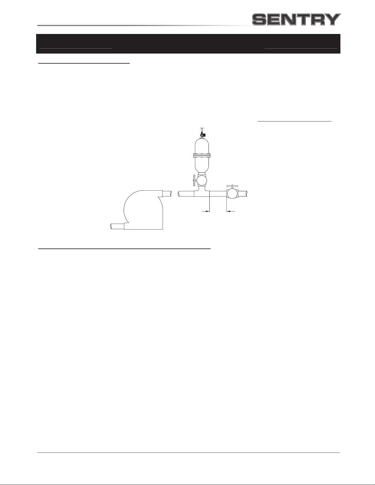
READ BEFORE INSTALLATION INSTALLATION FOR SURGE /
WATER HAMMER
READ BEFORE INSTALLATION
Step 1 — Installation Position
Install the dampener in-line, as close as possible to and before the device causing the water hammer pressure
spike (see FIGURE 2). For example, if a quick closing valve is causing water hammer, install the dampener on a
tee or elbow as close as possible upstream of the valve. Dampener installation should be no more than ten pipe
diameters from the valve. It is advisable to install an isolation valve between the dampener inlet and the
mounting tee so maintenance and pressure checks can be done while the system is operating.
Step 2 — Charging and Start-Up (see Pre-Charge Notes)
Chargeable models do not require an air line connection. Dampener can be pre-charged with compressed air up
to a maximum pressure of 150 psi (10.3 bar). If maximum pressure will exceed 150 psi (10.3 bar), dampener must
be pre-charged with Nitrogen only. Use a hand pump, Nitrogen tank or air compressor to charge dampener. DO
NOT USE OXYGEN. Charging hose kits are available from BLACOH.
The dampener must be pre-charged after installation but prior to system operation. The only method to get an
accurate pressure charge in the dampener is to charge it prior to system start up or with a closed isolation valve at
the dampener inlet. Pre-charge the dampener with 90% to 95% of expected system pressure. DO NOT USE
OXYGEN. A fill valve similar to a Schrader type tire valve but designed for suppressors, is mounted to the top of
the dampener. Replace fill valve cap after charging dampener and re-check dampener charge every month.
FIGURE 2
PUMP
SURGE SUPPRESSOR
QUICK CLOSING
VALVE
10 PIPE (Ø)
BLACOH
ISOLATION
VALVE

9BLACOH FLUID CONTROL, INC.
NOTES

BLACOH FLUID CONTROL, INC.10
MANUFACTURER’SLIMITED WARRANTY & RETURN POLICY
Standard Product Limited Warranty
Subject to the limitations set forth below, Blacoh Fluid Controls, Inc. ("Blacoh") warrants its products to be free
from defects in material and workmanship under normal use, service, and maintenance in accord with Blacoh’s
published specifications for a period of two years from date of shipment by Blacoh (the "Warranty"). The
EXCLUSIVE REMEDY for any product defect covered under this Warranty shall be one of the following, as
determined by Blacoh in Blacoh’s sole discretion: (a) refund of the purchase price; or (b) replacement or repair of
the defective part or parts at Blacoh’s facility. This Warranty will be null and void if the product is used in an
inappropriate application or if the product has been altered, misapplied, improperly installed, or not properly
inspected and maintained. To the maximum extent allowed by applicable law, Blacoh will not be responsible for
nor have any liability for any “Damage,” which means any of the following, whether the claim sounds in breach of
contract, breach of warranty, tort, strict liability, implied contractual indemnity, or otherwise: (i) any damage, loss,
or injury of any kind, or destruction, or death, whether or not caused by any defect in a Blacoh product and
whether or not the Blacoh product is installed, used, operated, and/or maintained in accord with Blacoh
instructions, to other products, machinery, buildings, property, or persons, and (ii) any costs, expenses, losses, or
incidental, consequential, or special damages of any kind or nature, including but not limited to loss of profits,
arising from or related to any Blacoh product, whether or not caused by any defect in a Blacoh product and
whether or not the Blacoh product is installed, used, operated, and/or maintained in accord with Blacoh
instructions. Damage resulting from chemical incompatibility or from over-pressurization of a product, whether
from gas or fluid, is not covered under this Warranty, nor will Blacoh be responsible in any way for any such
Damage. Because Blacoh does not determine and cannot anticipate or control the many different conditions under
which its products may be used, Blacoh does not warranty the applicability, suitability, or fitness of any of its
products for any particular use or purpose. Statements concerning the possible use of Blacoh products are not
intended and shall not be interpreted as warranties of fitness for any specific use of such products. Each user of
Blacoh products must conduct its own engineering analysis and tests to determine the suitability of each Blacoh
product for the user's intended uses or purposes, including but not limited to chemical compatibility and
pressurization, and any written or oral assistance from Blacoh in this regard does not relieve the user from
exclusive responsibility for such engineering analysis and testing. Blacoh products are sold with only this limited
Warranty, and each buyer assumes all responsibility for Damage (as defined above), including but not limited to,
Damage arising from defects in Blacoh products and/or from the handling and use of Blacoh products whether
used in accordance with Blacoh's directions or otherwise. Any products sold by Blacoh which are manufactured by
and sold under the name of another company are NOT WARRANTED by Blacoh under the foregoing Warranty or
otherwise. The buyer must rely exclusively on the product warranty, if any, given by such other company.
Products manufactured by Blacoh as an original equipment manufacturer (OEM) to be sold by a customer under
the customer’s brand and name are warranted by Blacoh only under the above Warranty, and Blacoh shall have no
liability whatsoever with respect to any representation or warranty given by such customer (or such customer’s
representatives, distributors, agents, employees, or independent contractors) to any of its buyers which is different
in any respect whatsoever from the foregoing Warranty. EXCEPT FOR THE WARRANTY GIVEN ABOVE, WHICH
IS SUBJECT TO THE ADDITIONAL LIMITATIONS STATED ABOVE, AND EXCEPT FOR THE ADDITIONAL
LIMITED WARRANTY ON BLACOH’S PTFE BELLOWS STATED BELOW, BLACOH GIVES NO WARRANTY OF
ANY NATURE WHATSOEVER, EXPRESS OR IMPLIED, WITH RESPECT TO ANY OF ITS PRODUCTS,
INCLUDING WITHOUT LIMITATION NO WARRANTY OF MERCHANTABILITY AND NO WARRANTY OF
FITNESS FOR A PARTICULAR PURPOSE. NO COURSE OF DEALING, USAGE OF TRADE, OR OTHER ORAL
OR WRITTEN STATEMENTS SHALL MODIFY THE FOREGOING WARRANTY PROVISIONS AND LIMITATIONS
IN ANY RESPECT WHATSOEVER. This Warranty shall be governed by and construed in accordance with the
laws of the State of California.
PTFE Bellows Limited Warranty
In addition to Blacoh's Standard Product Limited Warranty and subject to the limitations set forth below, Blacoh
warrants that its PTFE Bellows equipment (“PTFE Bellows”) on Blacoh's PTFE Bellows-fitted pulsation dampener
will perform in accordance with Blacoh's written product description for three years from date of shipment ("PTFE
Bellows Warranty"). This PTFE Bellows Warranty applies only to PTFE Bellows that are sized, charged, installed,
used, operated, and maintained strictly in accordance with all installation, use, operation, and maintenance
instructions provided by Blacoh, and failure to properly size, charge, install, use, operate, and maintain the PTFE
Bellows (or failure to do any of them) shall make the PTFE Bellows Warranty null and void. This PTFE Bellows
Warranty does not include applications where failure of performance is due to an unbalanced pressure load or a
transient pressure spike (sometimes called a water hammer). The EXCLUSIVE REMEDY for breach of this PTFE
Bellows Warranty is replacement of the PTFE Bellows at Blacoh’s facility, and not any other equipment or parts
whatsoever, and Blacoh will not be responsible for any Damage or any other loss of any kind, including but not
limited to incidental, consequential, or special damages (including but not limited to loss of profits), in any way
arising from failure of the PTFE Bellows to perform in accordance with Blacoh’s written product description. This
PTFE Bellows Warranty shall be governed and construed in accordance with the laws of the State of California.

M01E03.053
M13E11 060
Warranty Claims
1. Prior to returning any product to Blacoh based on a claim of breach of Warranty or PTFE Bellows
Warranty, a Blacoh Return Request form must be completed. The form will be reviewed by Blacoh to
determine if a Return Merchandise Authorization (RMA) number will be issued. The issuance of an RMA
number does not constitute Blacoh's acknowledgment or agreement that the warranty claim is justified or
correct.
2. If an RMA number is issued by Blacoh, customer should then deliver the product in question to the address
specified on the RMA, freight prepaid.
3. All products so returned to Blacoh based on a claim of breach of Warranty or of PTFE Bellows Warranty
must be cleaned, sanitized and neutralized prior to shipment to Blacoh. Blacoh will not accept any part
that contains corrosive chemicals, organic cultures, blood, any harmful residue or air borne materials that
might contaminate a breathable atmosphere or put at risk any person or property. Any shipment that does
not comply will be returned at the expense of the customer, or the customer will be required to arrange for
pickup.
4. HAZMAT SHIPMENTS WILL BE REMOVED AND PROCESSED AT CUSTOMER'S EXPENSE.
5. Receipt by Blacoh of a return does not constitute Blacoh's agreement that Blacoh is in breach of its
Warranty or PTFE Bellows Warranty.
6. If Blacoh determines that a defect in workmanship or material of a part has occurred, customer is not
entitled to a complete unit replacement. In the event of such a defect, Blacoh will repair or replace the
defective part or parts or refund the purchase price, as Blacoh determines in Blacoh’s sole discretion.
New Product Returns
1. If a customer wishes to return a new, unused product, the customer must first request a Return
Merchandise Authorization (RMA) number from Blacoh. Blacoh will determine if the unit can be returned
for possible credit.
2. Product to be returned must be new, unused, and of current design and purchased within thirty (30) days
of the return request. In addition the product must not have been damaged after original shipment by
Blacoh.
3. Product returns must be delivered, freight prepaid.
4. Blacoh has the right to inspect all returned products prior to acceptance or rejection.
5. ALL RETURNS are subject to a minimum $25.00 or 20% restocking fee, whichever is greater. (Higher
restocking fees may be charged on special items and some models may not be eligible for return).
Returns accepted by Blacoh will be credited to the customer's account less the re-stocking fee. Refunds
will not be issued.
6. Any outsourced product supplied by Blacoh will be subject to the warranty, return policy and re-stock fee
charged by the manufacturer of the outsourced product.
[L01E71.053]
BLACOH F
LUID
C
ONTROL
, I
NC
.
601 Columbia Ave, Bldg D
Riverside, CA 92507 USA
Phone: 951.342.3100
800.603.7867
Fax: 951.342.3101
Email: Sales@Blacoh.com
www.blacoh.com
This manual suits for next models
1
Table of contents
Other Blacoh Industrial Equipment manuals


Popular Industrial Equipment manuals by other brands


BVA Hydraulics
BVA Hydraulics H0203 instruction manual

Draco
Draco K9-1 instruction manual

Marini
Marini Quarry Votager Operating and maintenance manual

Siemens
Siemens SINEMA Remote Connect operating instructions

JJM Boiler Works
JJM Boiler Works JM Series Installation operation & maintenance

ABB
ABB HT609374 Operation manual


