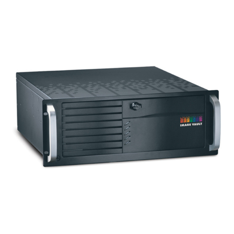
Image Vault Pro-Command User manual

APPENDIX A
Page | 1
Installation Manual
Pro-Command
DVR

Image Vault® Pro-Command version 9.4.3
Installation Manual
Page | 2
Installation Manual
Manual Edition J51613H
No part of this document may be reproduced in any form, electronic or mechanical, for any purpose without
written consent from Image Vault®, LLC. Information contained within this document is subject to change
without notice.
THE INFORMATION IN THIS PUBLICATION IS PROVIDED AS-IS WITHOUT ANY WARRANTY OF ANY KIND. THE
ENTIRE RISK ARISING OUT OF THE USE OF THIS INFORMATION REMAINS WITH THE RECIPIENT. IN NO EVENT
WILL IMAGE VAULT® BE LIABLE FOR ANY CONSEQUENTIAL, DIRECT, SPECIAL, INCIDENTAL, PUNITIVE OR OTHER
DAMAGES WHATSOEVER (INCLUDING WITHOUT LIMITATION, DAMAGES FOR LOSS OF BUSINESS PROFITS,
BUSINESS INTERRUPTION OR LOSS OF BUSINESS INFORMATION), EVEN IF IMAGE VAULT® HAS BEEN NOTIFIED
OF SUCH DAMAGES AND WHETHER INACTION OR CONTRACT, INCLUDING NEGLIGENCE.

Image Vault® Pro-Command version 9.4.3
Installation Manual
Page | 3
Table of Contents
Introduction 4
Technical Notes 5
Package Contents 6
Facilities 7
Front Panel 7
Rear Panel 8
Connectivity 11
Mounting DVR 11
Power 11
Input Devices 11
Monitor 11
Network Connections 11
Alarm Connections 12
Capture Cards 13
Connecting a PTZ 15
POS and Data Connectivity 15
Booting Up DVR 19
Appendix A 22
Appendix B 23
Technical Support 1-888-462-4382
Monday –Friday 8AM-5PM EST

Image Vault® Pro-Command version 9.4.3
Installation Manual
Page | 4
Introduction
Welcome to Image Vault®. This manual is intended for proper installation of the Image Vault® DVR and to
serve as a reference guide for troubleshooting if a problem occurs. Only trained installers should attempt
installing this product.
Warnings
WARNING: Your new Image Vault® DVR is a Personal Computer-based electronic
device. To perform a complete and satisfactory installation, Image Vault®
REQUIRES that an Uninterruptible Power System (UPS) be installed as part of the
digital recorder system. The Image Vault® recorder must be plugged into the battery
backup segment of the UPS and be the only attached device. Failure to properly
install a UPS may cause damage to the systems hard drive, resulting in a loss of
recorded images, or the inability to record and will void Image Vault®
Manufacturer’s warranty.
WARNING: Your Image Vault® DVR can operate as a stand-alone device, or may
be used remotely through a network via the Playback software. Regardless
of the connection or mounting methods, the case of the Image Vault® recorder
may not be modified or penetrated in any way. Any effort to mount other
equipment to the Image Vault®, modify the chassis, or penetrate the chassis in
any way will void Image Vault® manufacturer’s warranty.
WARNING: Do not power cycle the DVR while it is in the boot process,
as this may cause Operating System startup issues.

Image Vault® Pro-Command version 9.4.3
Installation Manual
Page | 5
Technical Notes
Ensure that the power switch located on the back left of the Image Vault® is switched to the OFF position before
plugging into a power source.
Do not remove the power ground pin from the power connector. Grounding is essential to the proper
performance of the DVR and UPS and will void manufacturer’s warranty if removed.
Plug the DVR power cord into the UPS. Ensure the UPS is connected to a 110/115v grounded receptacle that is
easily accessible at all times.
Refrain from installing the Image Vault® in a location that is excessively humid or dusty. These environmental
factors can result in electrical malfunction or general damage to the device. The installation environment
temperature must not exceed 95°F/35°C. Operating Temperature: 41°-104°F.
For proper ventilation you must provide 3 inches minimum clearance in both the front and back of the DVR.
The Image Vault® filter (item A on diagram 7.1) must be cleaned monthly. Remove the filter and clean dust and
debris from the filter using condensed air, then return the filter to the unit.
Do not install the Image Vault® in any location where it may be susceptible to outside electromagnetic fields or
vibrations, as this may interfere with the operation of the device. Some common sources of interference are
radios, florescent ballasts, TV’s, stereo equipment, etc.
Do not store or temporarily place heavy objects or components on top of the Image Vault®.
Image Vault® Pro Command Software includes a built-in help system which may be accessed at any time
from the Help menu. This is accessible both on the DVR itself and the Remote Playback Software located
on your PC. If a keyboard is connected, you may also connect by pressing F1 at any time.

Image Vault® Pro-Command version 9.4.3
Installation Manual
Page | 6
Package Contents
The Image Vault® package contents are:
Quick Reference Guide (page 28)
Audio Disclaimer (page 25)
Installation Considerations (page 26)
IVPTZAOC connection diagram (page 24)
Warranty Document (page 27)
Integration Facility Checklist
Black Jewel Case with Playback CD and printed manual
Window Door Decal x1
Blank CD
10’ Patch Cable
IVPTZAOC Cable
Optical Mouse (USB/PS2)
Power Cord
Model Specific Video/Audio Pigtails
Keys to Chassis
Optional Components – Additional POS Connections, Alarm Input cables*
*Contact Dealer for details and recommendations

Image Vault® Pro-Command version 9.4.3
Installation Manual
Page | 7
Facilities
This section provides detailed information about common hardware components.
Front Panel
A. Front Ventilation. The front panel air vent cover is removable for easy filter cleaning. A monthly
cleaning of the filter is recommended.
B. Power Switch. Rocker switch turns the DVR on or off.
C. Reset Switch. Push button reset switch causes the DVR to shut down and automatically reboot.
D. On-Off Indicator. Tells you the unit has power and is turned on.
E. USB Input. For connection of mouse, keyboards, or thumb drives.
F. Camera Recording Indicator. Tells you that the unit is currently writing video images to its hard drive.
C
A
B
D
E
F
Front Panel
Diagram 7.1
C

Image Vault® Pro-Command version 9.4.3
Installation Manual
Page | 8
Rear Panel
A. AC Power Input. Standard 3-prong IEC inlet.
B. Power Supply Switch. Use this switch to completely remove power. Turning this switch on does not
automatically start the recorder (refer also to Front Panel Power Switch).
C. Mouse. For a PS/2 Style Mouse.
D. Keyboard. For a PS/2 Style Keyboard.
E. Serial Port 2 (Data Device). For connection of a second data device.
F. VGA (Monitor). For connection of a VGA monitor.
A
B
G
C
D
E
H
I
J
M
Rear Panel 16/480 Unit
F
K.1
L
N
Diagram 8.1
K

Image Vault® Pro-Command version 9.4.3
Installation Manual
Page | 9
G. Network Interface Card. For connection to the network.
H. USB Port(s). For connection of USB devices such as keyboards, mice, USB thumb drives, etc.
I. Alarm Output. For connection of watchdog and secondary alarm relay(s) output(s).
J. Alarm Input. For connection of up to 16 input for triggering external input rules.
K. Capture Card(s). For connection of up to 32 analog cameras depending on model of DVR utilizing male
BNC connectors. Also allows for connection of up to two public view monitors (PVM) utilizing female
RCA connectors. (add specific unit info)
K.1 Capture Card port 9-16 on PROC16480-XX, port 17-32 on PROC32240-XX
L. Audio Inputs. For connection of up to 16 audio sources. Utilizes a female RCA connector.
M. Serial Port 1(Data Device 1). For connection of a data device
N. Public View Monitor Connector. For connection of a public view monitor on PROC16480 only.
(See diagram 13.1)

Image Vault® Pro-Command version 9.4.3
Installation Manual
Page | 10
A
B
G
C
D
E
H
I
J
F
K
L
M
Rear Panel 32/240 Unit
Diagram 9.1

Image Vault® Pro-Command version 9.4.3
Installation Manual
Page | 11
Connectivity
This section provides detailed information about connecting power, keyboard, mouse, VGA monitor, video,
audio, and data devices.
Mounting
The Image Vault® is a 4U rack mountable DVR, which can be installed as a free-standing unit. For
suspended mounting you will require the optional mounting bracket part # IVBRACK4SP.
Power
Make sure the power switch (B –Diagram 8.1) is in the off position. Connect the provided power cord to
the power cord inlet (A–Diagram 8.1). Do not connect to building power AC outlet at this time.
Input Devices
Connect the provided mouse to the PS/2 mouse input (C–Diagram 8.1). The Image Vault® is a mouse
driven system and a keyboard is not necessary for setup and use. However, if you wish to install a
keyboard you may connect it to the PS/2 keyboard input (D–Diagram 8.1) or one of the available USB ports
(H–Diagram 8.1).
Monitor
Connect a VGA monitor to the VGA output (F–Diagram 8.1). A monitor is not required for operation of the
Image Vault®, but is necessary for initial setup and configuration.
Network Connection
You may connect your Image Vault® DVR to a network connection utilizing the supplied Ethernet port (G–
Diagram 8.1). The Image Vault® DVR may have up to four Network Interface Cards installed. We advise
using the onboard NIC (G–Diagram 8.1) for connection to network. Additional Network Interface Cards
may be used for maintaining PCI compliance across Point of Sale devices, and segregating IP cameras due
to bandwidth allocation.

Image Vault® Pro-Command version 9.4.3
Installation Manual
Page | 12
Alarm Connection.
Connect the Image Vault® alarm outputs in accordance with the provided IVPTZAOC wiring diagram
(APPENDIX B). The Image Vault® DVR allows up to 16 alarm inputs. To connect external inputs you will
need a DB25 cable, or DB25 pin out connector. The pin out is in numerical order. Pin 1 is input 1, pin 2 is
input 2. This continues through input 16. Pins 17-25 are all “common” grounds. To initiate a trigger, short
any input to any common. Alongside programmed variables this will report an input event to the Image
Vault®.

Image Vault® Pro-Command version 9.4.3
Installation Manual
Page | 13
Capture Cards
PROC16480-XX:
The PROC16480 model can connect up to 16 cameras at an accumulative capture rate of up to 480 frames
per second. Use a provided whip cable to connect cameras 1-8 to the (K diagram8.1) DB15 port on the
capture card. Use the second whip cable provided to connect cameras 9-16 (K.1 Diagram 8.1) DB15 to the
top female DB port on the capture card.
The PROC16480 model can connect up to 16 audio inputs. Use the provided audio whip cable to connect
the audio input to the DVR. The audio inputs are assigned to the cameras in numerical order.
Diagram 13:1
The PROC16480 model has a single public view monitor output (PVM) (M–Diagram 8.1). Although there
are four physical connections on the PVM card, only utilize BNC output 1. The remaining PVM ports are
not active at this time and are for future development.

Image Vault® Pro-Command version 9.4.3
Installation Manual
Page | 14
PROC32240-XX:
The PROC32240 model can connect up to 32 cameras at an accumulative capture rate of up to 240 frames
per second. Use a provided whip cables to connect the DVI ports on the back of the DVR and connect
cameras. Cameras 1-8 connect to DB 15 (K diagram 8.1), cameras 9-16 connect DB15 (K.1 Diagram 8.1)
Image 14.1
The PROC32240 model can connect up to 16 audio inputs. Use the provided cable(s) to connect the audio
input on the back of DVR. On the 32/240 card each audio input is associated with 2 cameras. See table
below:
Table 14.1
INPUT
CAMERAS
INPUT
CAMERAS
1
1 & 2
9
17 &18
2
3 & 4
10
19 & 20
3
5 & 6
11
21 & 22
4
7 & 8
12
23 & 24
5
9 & 10
13
25 & 26
6
11 & 12
14
27 & 28
7
13 & 14
15
29 & 30
8
15 & 16
16
31 & 32
Cameras 1-8 and active
output 1(3)
Cameras 17-32 and active
output 1(3)

Image Vault® Pro-Command version 9.4.3
Installation Manual
Page | 15
Connecting a PTZ Camera
To attach a PTZ camera use the included IVPTZAOC wiring diagram (also located in Appendix B).
POS and Data Device Connectivity
Point of sale (POS) and data devices can be connected utilizing serial or network connections. There are
three methods of serial connections and four methods of network connections. Additional data cables
may be required for proper connection to POS or data devices. See Appendix A for more information.
Serial Connection:
Direct Connection to a Single Data Device
Direct Connection to a Multi-Device Server
IV Quad
Network Connection:
Direct Connection to a Single Data Device
Direct Connection to a Multi-Device Server
Direct Connection to Multiple devices
Direct Connection to MultiCast Stream
Serial Port 1
Serial Port 1 is for direct Point of Sale (POS) or data device serial connectivity. It collects the data stream
and transforms it into text to be displayed in our software. It can be connected utilizing one of the three
methods described above.

Image Vault® Pro-Command version 9.4.3
Installation Manual
Page | 16
Example 1 Single Data Device:
Example 2 Multi-Device Server:

Image Vault® Pro-Command version 9.4.3
Installation Manual
Page | 17
Example 3 IV Quad:
Serial Port 2
Serial Port 2 is for an additional direct Point of Sale (POS) or data device serial connectivity. Serial Port 2
doubles the connectivity options serially. For example, you can have 2 IV Quads for connection of up to 8
single data devices.

Image Vault® Pro-Command version 9.4.3
Installation Manual
Page | 18
Network Data Device Connections
The Image Vault® can connect to POS or data devices via the network using the aforementioned methods.
Capturing POS data from a network print server does not require any additional cables. The DVR must be
connected to the same local network as the POS data source. Coordinated software configuration of the
network print server(s) and DVR is required. Within the software configuration, you may configure the
DVR to receive POS data directly from up to two separate Ethernet connections as a Single Data device,
Multi-Device Server, Multiple Devices, or a Multi-Cast stream.

Image Vault® Pro-Command version 9.4.3
Installation Manual
Page | 19
Booting Up DVR
Congratulations! You are now ready to power up the system and check the operation.
Turn on the monitor and any other peripherals connected to DVR.
Confirm all cameras are powered on.
Connect the DVR to an isolated UPS, and connect the UPS to building AC power.
How to check if the system is working properly
Press the power button on the front of the DVR.
Within a couple of minutes of power-up, you should hear a series of beeps. The number of beeps will
equal the number of active cameras detected. If a video monitor is connected to the monitor output(s),
you should begin seeing video from the cameras, switching approximately every four seconds (by default).
Wait a minimum of five (5) minutes before attempting to connect to the system. The DVR must begin
capturing and storing images in order to properly begin configuring cameras.
At this point the DVR is operating properly and recording images. The system is operating with default
settings that are pre-programmed in the unit.
After boot is complete, log into the DVR with proper credentials.
User Name: SERVICE
Password: SERVICE
Once you have successfully logged into the software start you configuration. Only shut down the DVR
using the software. Do not shut down the DVR by removing AC power. Only use the reset button or
power rocker switch when advised by Image Vault® technical support.

Image Vault® Pro-Command version 9.4.3
Installation Manual
Page | 20
Notes
Table of contents
Other Image Vault DVR manuals
Popular DVR manuals by other brands

Honeywell
Honeywell Rapid Eye installation guide

Sony
Sony Walkman GV-8 operating instructions
SECPRO SIKRING
SECPRO SIKRING SP-LS400 user manual
VisionQuest
VisionQuest DIY-4350 instruction manual

Planet Networking & Communication
Planet Networking & Communication HDVR-430 user manual
Hunt
Hunt HDR-04FE user manual
