Images SI DTG-01 Guide


Contents
1. Introduction..................................................... 3
Features...................................................... 4
Main Panel Controls . . . . . . . . . . . . . . . . . . . . . . . . . . . . . . . . . . . . . . . . . . . . 5
USB/TTLAdapter.............................................. 6
2. Operation........................................................ 7
Survey Meter Modes . . . . . . . . . . . . . . . . . . . . . . . . . . . . . . . . . . . . . . . . . . . . 7
Random Number Generator . . . . . . . . . . . . . . . . . . . . . . . . . . . . . . . . . . . . . . . 8
Graphing Software . . . . . . . . . . . . . . . . . . . . . . . . . . . . . . . . . . . . . . . . . . . . . . 9
3. Geiger Counter and Radiation Basics . . . . . . . . . . . . . . . . . . . . . . . . . . . . . . . . . . 12
Radioactivity . . . . . . . . . . . . . . . . . . . . . . . . . . . . . . . . . . . . . . . . . . . . . . . . . . 12
Geiger Muller Tube . . . . . . . . . . . . . . . . . . . . . . . . . . . . . . . . . . . . . . . . . . . . . 12
Count Rate Vs Dose Rate . . . . . . . . . . . . . . . . . . . . . . . . . . . . . . . . . . . . . . . . .13
Measurement of Radiation . . . . . . . . . . . . . . . . . . . . . . . . . . . . . . . . . . . . . . . . 14
How Much Radiation is Safe? . . . . . . . . . . . . . . . . . . . . . . . . . . . . . . . . . . . . . 15
Checking for Radiation . . . . . . . . . . . . . . . . . . . . . . . . . . . . . . . . . . . . . . . . . . 16
Finding Radioactive Sources. . . . . . . . . . . . . . . . . . . . . . . . . . . . . . . . . . . . . . 17
Separating and Detecting Alpha, Beta & Gamma . . . . . . . . . . . . . . . . . . . . . . 17
NIST Calibration / NRC Certification and Why It’s Important . . . . . . . . . . . . 18
Generation of Random Numbers . . . . . . . . . . . . . . . . . . . . . . . . . . . . . . . . . . . 19
How Random Numbers are Generated from Background Radiation . . . . . . . .19
4.Appendix........................................................ 20
Technical Specifications . . . . . . . . . . . . . . . . . . . . . . . . . . . . . . . . . . . . . . . . . .20
Warranty

DTG-01 3
1. Introduc t ion
The model DTG-01, Desktop Geiger Counter has an external wand that houses the Geiger Mueller tube.
Scientific Instrument & Industrial Tool
Our Digital Geiger counters have been calibrated and certified accurate in reading radiation levels to with-
in 5% from background radiation to 1000 mR/hr. NRC Certification available at additional cost.
Perfect for schools and industry. In the laboratory the Digital Geiger Counter may be used to conduct nu-
clear experiments and measurements. Free Windows 7 graphing programs. Graphic Files may be exported
to Excel spreadsheets.
Communication specifications are provided for users to read the output of the Geiger Counter and write
their own programs.
Applications
*Education - Classroom demonstrations and experiments
*Emergency Services and Domestic Preparedness
*HAZMAT and Compliance Verification
*Dirty Bomb Screening and EMT's
Features

4 Images SI, Inc.
Radiation Detected
Alpha, Beta, Gamma and X-Rays.
Detector
Geiger-Muller tube Ne + Halogen filled with a .38" effective diameter 1.5-2.0 mg/cm2 mica end win-
dow.
Detector Sensitivity
· Alpha above 3.0 MeV
· Beta above 50 KeV
· Gamma above 7 KeV
Countable Pulse Range 1 (CPM) - 10000 + counts per second (CPS)
Converted Radiation Range .05 mR/hr - 1000 mR/hr (Imperial)
.0005 mSv/hr - 10.0 mSv/hr (SI Metric)
The Liquid Crystal Display (LCD) is 16 character by 2 line that provides an easy to read output, see image
to right. LCD has an on-off backlight switch . LCD display continuously updates counts per second (or
counts per minute) on line one while displaying converted radiation level second line.
Backlight Switch turns on and off the LCD backlight,.
The LED marked Pulse—is a secondary radioactive particle indicator it blinks each time a radioactive par-
ticle is detected by the Geiger Counter.
The PowerSwitch turns power on or off to the DTG-01.
The SpeakerSwitch turns the sound on or off to the internal speaker. The speaker is a secondary radioac-
tive particle indicator. It clicks each time a radioactive particle is detected. Note: Plugging a headphone in
the headphone jack will automatically turn off the internal speaker.
Headphone jack is a standard 3.5mm for private listening. Using a headphone automatically turns
off the internal speaker of the Geiger counter.
External power jack is available for extended readings where battery operation may not be practi-
cal. Power jack is 2.5mm x 5.5mm. Power input is 9VDC or 9VAC @ 200mA min. current. Mobile oper-
ation uses a 9V battery.
TTL Serial and Digital Pulse outputs for PC available via 3.5MM stereo connector.
Random Number Generator function outputs a range of random numbers for every radioactive
particle detected.
Included 9V wall transformer powers the DTG-01 by connecting to the back of the unit by way of a
2.1/5.5mm jack and socket.

DTG-01 5
Main Panel Controls
The top left switch starting from the selects whether the radiation levels are shown in Systems Inter-
national (SI) metric (mSv/hr) or imperial (mR/hr) measurements.
The top right switch labeled CPS / CPM selects one Survey Meter Modes:
CPS (Counts Per Second) is a one second counting
mode. Real time radiation readings and displays the
count/second and equivalent radiation level in either
mR/hr or mSv/hr.
CPM (Counts Per Minute) is a one minute count-
ing mode for measuring low levels of radioactivity
and background radiation: Displays accumulated
count and equivalent background radiation in either
uR/hr or uSv/hr. If radiation level is significant radia-
tion level is displayed either mR/hr or mSv/hr.
The bottom left switch turns the unit on / off. A green LED next to the ON label will indicate that the
unit is powered on.
The bottom right switch controls the Random number Generator function. It allows the user to
choose between outputting radiation levels or 2 ranges of random numbers. To have the desktop Geiger
Counter output radiation levels this switch must be in the center position (RNG OFF). When the switch is
moved to the up position the random number generator will output numbers in the range of 1-2. When the
switch is in the down position, the random number generator will out put numbers in the range of 1-128.
More information on using the random number generator function can be found on page 8.

6 Images SI, Inc.
The image above shows the controls located on the right side of the front panel. The external wand con-
taining the Geiger Muller tube is connected on the far right of the panel. Above this connection is the Pulse
LED that will flash for each radioactive particle detected. In addition to the LED, the unit also has
an audio feature. Sound may be turned on and off by using the switch found on the lower left of this side of
the panel. Users may choose to connect headphones to the 3.5mm jack next to the audio switch. When
headphones are plugged it, they override the audio switch and no external sound will be heard.
Data from the unit may be exported to PC by using either the TTLSerial Output or Digital Pulse Output
jacks. A 3.5mm stereo to USB cable connected from the TTL Serial Output to PC will allow you to output
data to Images’ Digital Geiger Counter Graphing Software.
Other programs may require Pulse data, which can be obtained by plugging a 3.5mm mono cable into the
Digital Pulse Output.
USB /TTL Cable Adapter (sold separately)
Serial data consisting of the CPS counts may be read by a Windows PC
computer using a USB/TTL Serial Cable, included. USB TTL Serial Ca-
ble allow easy interfacing of the DTG-01 via USB. The cable has a USB
connector on one end that plugs into PC, and a 3.5mm stereo jack that
plugs into the DTG-01.
3.5mm audio jack output configuration:
tip - TxD
ring - RxD
sleeve - GND
*See page 7 for changing data output to jack’s Tip or Ring. Useful for
using 3rd party TTL Serial/ USB cables.

DTG-01 7
2. Oper atio n
Survey Meter Modes
To set the Desktop Geiger Counter in Survey Meter mode, ensure that the Random
Number Generator Switch is in the center position (RNG Off).
CPS Mode: Set the Conversion switch to mR/hr (milliroentgen/hour). The time function switch to
“CPS”, Backlight switch on and the audio switch on. Turn on the Geiger counter. If you have a radioactive
source bring the source close to the GM tube. For Geiger counters with an external wand, bring the wand
close to the radioactive source.
Every radioactive particle detected will cause the Geiger counter to click and the LED to blink.
The LCD digital display in this mode updates the count and radiation level every second, see photo above.
The display always shows the previous seconds count and radiation level. The count “Count/Sec” is the
number of radioactive particles detected in the previous second. On the second line the equivalent radiation
level of that count in mR/hr. You can change the Conversion switch to mSv/hr to read the radiation level in
milli-sieverts/hour.
The CPM mode displays the counts per minute and convert the radiation level into micro-Roentgens
(uR/hr) or micro-Sieverts (uSv/hr). The CPM modes is useful for checking background radiation. First set
the switch to Metric or Imperial measurement. Next set the time function switch to CPM. The LCD display
changes. The left side of the first line begins a count up to 60 seconds, increasing by 1 each second. The
right hand side of the first line displays the number of radioactive particles detected.

8 Images SI, Inc.
At the end of the CPM count the Digital Geiger counter will display the total CPM and equivalent radia-
tion level for one second before beginning another CPM counting cycle.
If you changed to the 1 minute time from 1 second the second line will display the radiation level last cal-
culated from the previous mode. If the Geiger counter is turned on in the 1 minute mode the second line
will display the word “Initializing” for the first 60 seconds.
Random Number Generator
The DTG-01 has a built in Random Number Generator (RNG).
A three position switch controls the RNG. In it’s center position the RNG is
off, and the DTG-01 operaties in Geiger Counter Mode.
When switched to either the 1-2 number range or 1-128 number range, the
RNG will generate random numbers in the set range using radioactive particle
detection.
The random number is displayed on the LCD screen and sent out serially
through the TTL Serial Port.

DTG-01 9
Digital Geiger Counter Graphing Software
We offer a Windows PC program that reads this serial information for charting and recording the meas-
ured radiation over time (see screenshot below).
A free lite version of our Geiger graphing software can be downloaded at:
www.imagesco.com/geiger/geiger-graph.html
The Radiation Monitoring and Graphing software is useful for monitoring radiation. The software con-
stantly monitors for the Counts Per Second (CPS) values and plots them on the Graph when connected to
one of our Digital Geiger Counters. It calculates radiation levels from incoming serial data and plots them
along with the CPS values. The software is capable of capturing values for different time units (i.e., Sec-
onds, Minutes, Hours or Days). The recorded data can be saved, and exported as a CSV delimited file for
use in various other applications including Word & Excel. Data can be displayed as 1 of 4 types of graphs.
One can also set alarm levels for CPS/Radiation Levels. If the values cross the specified levels, the soft-
ware issues a visual and an audible alert.
Installing the Software Package
Begin by installing the appropriate drivers for the USB/TTL cable included with the purchase of the soft-
ware program and/or cable. These drivers may also be downloaded from the Images website at:
http://www.imagesco.com/semiconductors/usb-3.5mm.html
Once the drivers are installed, restart your computer and then plug the cable into an available USB port.
Now install the Windows Geiger counter program on your computer. The digital Geiger counter has TTL

10 Images SI, Inc.
serial output. Connect the Geiger counter to the computers serial port using the USB TTL serial cable.
Make sure the serial/TTL jumper is set to serial, see “Setting the Back Jumpers/Contrast Control” in the
Appendix.
When opening the application, make sure the program’s COM port is set to the correct COM port where
the USB cable and Geiger counter has been connected. A troubleshooting guide for the com port is also
included in the Appendix.
The Geiger counter must be on and connected to the computer for the program to begin graphing. To
begin graphing simply click “Start” in the lower left hand corner of the main interface screen.
The main program interface is comprised of the following components:
The main graph on which the values will be plotted.
Time options frame. This allows user to select different time units (Second, Minute, Hour,
Day) For example, if you set the time unit to Second, then the program will count the radiation
levels per second, and plot. If you set it to Minute, the program will count radiation levels per mi-
nute, and plot.
Graph type frame. This allows user to switch between different views of graph (Line Chart,
3D Line Chart, Bar Chart and 3D Bar Chart).
Plot frame. This comprises of the Start button which starts the capturing and plotting pro-
cess. When capturing is in progress, the same button will act as a Stop button, which stops captur-
ing and plotting process.
Graph frame. This comprises of a Clear button which clears the graph, a Save button which
saves values to the active file, a Save As button which allows to select a different file for saving,
and Viewer button which launches the Viewer.
mR/hr frame. This comprises of a textbox which displays current radiation level.
Serial Port frame. This comprises of a combo box which allows com port selection.
Status frame. This comprises of an LED which displays the status of the program. The status
LED changes according to the activity. When no capturing is in progress, the LED will be Off and
status will be Stopped. When the program is receiving values, the LED will be Blue and status
will be Receive. When program is writing the values, the LED will be Green and status will be
Write.
Real Time Data frame. This frame displays various real time values such as Counts Per Sec-
ond (CPS), total accumulated count (if the program is running on modes other than Second), time
left before next update, and total number of points captured.
Others frame. This comprises of a Print Chart button which allows to prints the current
plot, a Settings button which opens the Settings dialog, an About button which displays the infor-
mation about the program, and an Exit button which quits the program.

DTG-01 11
The image below outlines where each frame is located and shows data being displayed as a line graph.
The image on the previous page shows the data in a bar graph.
Writing Your Own Interface Software
It is possible to write your own software to read the data from the digital Geiger counter. The data is out-
putted from a 3.5 MM stereo jack, as shown on previous page. The +5V serial data is sent out as a two
byte number (most significant byte first) with the following specifications: 9600 Baud, Inverted, 8 data
bits, no parity and one stop bit.
The Serial Data Output is a two byte (8-bit) number every second that represents the previous count per
second. High byte is followed by the low byte. Communication parameters are: 9600 Baud, Inverted, 8 da-
ta bits, no parity and one stop bit. These parameters are for anyone wishing to read the data from the Digi-
tal Geiger counter.

12 Images SI, Inc.
3. Gei ger Co unter and
R adia tion Basics
Radioactiv ity
Radioactivity is the spontaneous emission of energy from the nucleus of certain elements, most notably
uranium. There are three forms of energy associated with radioactivity; alpha, beta and gamma radiation.
The classifications were originally made according to the penetrating power of the radiation.
Alpha rays were found to be the nuclei of helium atoms, two protons and two neutrons bound to-
gether. Alpha rays have a net positive charge. Alpha particles have weak penetrating ability; a couple of
inches of air or a few sheets of paper can effectively block them.
Beta rays were found to be electrons, identical to the electrons found in atoms. Beta rays have a net
negative charge. Beta rays have a greater penetrating power than Alpha rays and can penetrate 3mm of alu-
minum.
Gamma rays are high-energy photons. This has the greatest penetrating power being able to pass through
several centimeters of lead and still be detected on the other side.
Images Digital Geiger Counters are sensitive to all three types of radioactivity.
The Geiger Mueller Tube
Geiger Mueller tubes are simple devices that detect and measure radioactivity. The original design by H.
Geiger and E.W. Mueller in 1928 hasn't change very much. The basic sensor functioning remain the same.
A cutaway drawing of the tube is shown below. The wall of the GM tube is a thin metal cylinder (cathode)
surrounding a center electrode (anode). It is constructed with a thin Mica window on the front end. The
thin mica window allows the passage and detection of alpha particles. The tube is evacuated and filled with
Neon, Argon plus Halogen gas.
DTG-01 13
It is interesting to see how the GM tube detects radioactivity. A 500-volt potential is applied to the anode
(center electrode) through a ten mega-ohm current limiting resistor. To the cathode of the tube a 460-k ohm
resistor is connected.
In the initial state the GM tube has a very high resistance. When a particle passes through the GM tube, it
ionizes the gas molecules in its path. This is analogous to the vapor trail left in a cloud chamber by a parti-
cle. In the GM tube, the electron liberated from the atom by the radioactive particle and the positive ion-
ized atom both move rapidly towards the high potential electrodes of the GM tube. In doing so they collide
with and ionize other gas atoms. This creates a small conduction path allowing a momentary surge of elec-
tric current to pass through the tube.
This momentary pulse of current appears as a small voltage pulse across R2. The halogen gas quenches
the ionization and returns the GM tube to its high resistance state making it ready to detect radioactivity.
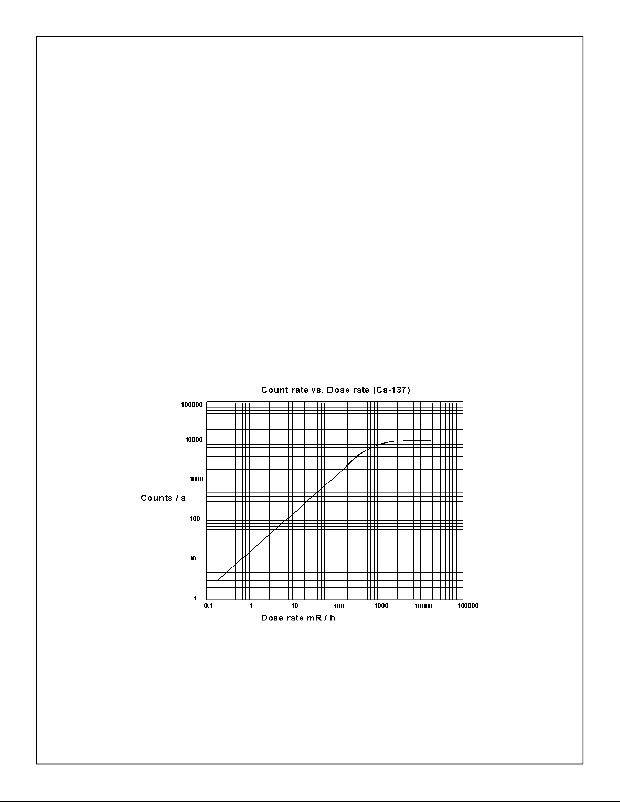
Count Rate vs Dose Rate
Each output pulse from the GM tube is a count. The counts per second give an approximation of the
strength of the radiation field. Below is the GM tube used in the DTG-01’s response to a cesium-137
source.

14 Images SI, Inc.
Measurement of Radiation
There are a few scales that one can use to measure radiation. Depending upon your application, one scale
may be better than the others.
Radiation Measurements
Roentgen: Is the measurement of energy produced by Gamma or X-Ray radiation in a cubic centimeter of
air. It is abbreviated with the capital "R". One milliroentgen, abbreviated "mR" is one-thousandth of a
roentgen. One microroentgen, abbreviated “uR” is one-millionth of a roentgen.
RAD: Radiation Absorbed Dose. Original measuring unit for expressing the absorption of all types of ion-
izing radiation (alpha, beta, gamma, neutrons, etc) into any medium. One rad is equivalent to the absorp-
tion of 100 ergs of energy per gram of absorbing tissue.
REM: Roentgen Equivalent Man is a measurement that correlates the dose of any radiation to the biologi-
cal effect of that radiation. Since not all radiation has the same biological effect, the dosage is multiplied by
a "quality factor" (Q). For example, a person receiving a dosage of gamma radiation will suffer much less
damage than a person receiving the same dosage from alpha particles, by a factor of three. So alpha parti-
cles will cause three times more damage than gamma rays. Therefore, alpha radiation has a quality factor
of three. Following is the Q factor for a few radiation types.
The difference between the rad and rem is that the rad is a measurement of the radiation absorbed by the
material or tissue. The rem is a measurement of the biological effect of that absorbed radiation.
For general purposes most physicists agree that the Roentgen, Rad and Rem may be considered equivalent.
System International (SI) of Units
The System International of unit for radiation measurements is now the official system of measurements.
This system uses the “gray” (Gy) and “sivert” (Sv) for absorbed dose and equivalent dose respectively.
The conversion from one system to another is simple:
Radiation:Quality Factor (Q)
Beta, Gamma and X-rays 1
Thermal Neutrons 3
Fast n, a, and protons 10
Heavy and recoil nuclei 20
1 Sv = 100 rem 1 rem = .01 Sv
1 mSv = 100 mR (mrem) 1 mR = .01 mSv
1 Gy = 100 rad 1 rad = .01 Gy
1mGy = 100 mrad 1 mrad = .01 mGy
DTG-01 15
How Much Radiation is Safe?
In the United States, the U.S. Nuclear Regulatory Commission (NRC) determines what radiation exposure
level is considered safe. Occupational exposure for worker is limited to 5000 mrem per year. For the
general population, the exposure is 500 mrem above background radiation in any one year. However for
long term, multi-year exposure, 100 mrem above background radiation is the limit set per year.
Let’s extrapolate the 100 mrem number to an hourly radiation exposure rate. There are 365 days/yr x 24
hr/day equals 8760 hours. Divide 100 mrem by 8760 hours equals .0114 mrem/hr or 11.4/hr microrem.
This is an extremely low radiation level. The background radiation in my lab hovers around 32 uR/hr. Am
I in trouble? No. Typically background radiation in the United States averages 300 mrem/yr, or 34
microrem/hr. The NRC specifications is for radiation above this 34 urem/hr background radiation.
Notice that my lab readings are in microrad (uR/hr) and the exposure limit is given in microrem (urem/hr).
I do not know what type of radiation (a , b or y) the geiger counter is reading in my lab at any particular
instant, so I do not know the Q factor of the radiation and therefore can not calculate the mrem. However
for general purposes I consider them the one and the same. Remember, the digital geiger counters are
calibrated using a Cs-137 radioactive source. Therefore the highest accuracy in reading radiation levels
will be from Cs-137 sources.
Common Radiation Exposure (General Population)
Background radiation consists of three sources; Cosmic radiation from the sun and stars. Terrestrial
radiation from low levels of uranium, thorium, and their decay products in the soil, air and water.
Internal radiation from radioactive potassium-40, carbon-14, lead-210, and other isotopes found inside
our bodies.
Because of the randomness of radioactivity, background radiation can vary from minute to minute and
place to place. In my corner of the world I have a background radiation that triggers the counter 22-34
times a minute.
Exposure Source Dose(conventional) Dose (SI)
Flight from LA to NY 1.5 mrem .015 mSv
Dental X-ray 9 mrem .09 mSv
Chest X-ray 10 mrem 0.1 mSv
Mammogram 70 mrem 0.7 mSv
Background Radiation 620 mrem/year 6.2 mSv/year

16 Images SI, Inc.
Checking for Radiation
Our line of Digital Geiger Counters are extremely sensitive and will detect and measure background radia-
tion in addition to detecting and measuring radioactivity above background radiation. To test for small in-
creases in radioactivity that may be present in food and other materials to cause a increase in the back-
ground radiation one must first establish the background radiation level.
To obtain your normal background radiation reading take an hour's worth (60) of one minute readings.
This is the CPM (counts per minute) mode on the DTG-01. With this data collected. I would add the 60
readings together. I would then take that total and divide it by 60 to get an average CPM reading. Next I
would look through the 60 CPM readings and mark down the highest count CPM reading, and the lowest
count CPM reading. Those two CPM numbers are your Max and Min.
With this information, you can determine if the background CPM radiation reading(s) are greater than
your MAX CPM number. If the readings are consistently greater, you can make a logical assumption that
there is an increase in background radiation.
To see the percentage increase you would subtract the average CPM number from your reading to see
what the increase in radiation is on average.
To increase accuracy, you could also average say five hours worth of data or 300 one minute CPM sam-
ples to obtain the average CPM, Min CPM and Max CPM. In general the greater the number of samples
the greater the level of confidence. The CPM averages may be different for day and night, so you may also
want to collect background radiation data for time variances.
The optional Geiger Counter Graphing Software for Windows PC (see page 8), also available on Amazon,
ASIN: B00WAK68U4, will allow you to collect, monitor and save this data from the DTG-01 easily.
To run a test, position the probe (or Geiger counter) very close to the top surface of the material you are
testing, and run the counter in its CPM mode to check for radiation above your established background
radiation.
Finding Consistency in Readings
Because of the randomness of radioactivity, your readings may vary from second to second. To help “even
out” the readings, the DTG-01 has a built in “smoothing feature. This feature is activated by putting the
center switch into AVG CPS Mode. The read out will display a running 3 second average.

DTG-01 17
Finding Radioactive
Sources
The mantle in some Coleman lanterns are radioactive. Bring your Geiger counter to a local hardware store
and check them out.
Uranium ore from a mineral or a rock store should also emit sufficient radiation to trigger the counter.
A more reliable source is to purchase a radioactive source. Small amounts of radioactive materials are
available for sale encased in 1 inch diameter by ¼" thick plastic disks. The disks are available to the gen-
eral public license exempt. This material outputs radiation in the micro-curie range and has been deemed
by the Federal government as safe.
The cesium-137 is a good gamma ray source. The cesium 137 has a half-life of 30 years.
Radioactive uranium ore and radioactive isotopes are available for purchase from Images Scientific In-
struments. http://www.imagesco.com/geiger/radioactive-sources.html
Sepa rating & D etecti n g A lpha , B eta and Gamma
By placing shields of different materials in front of the GM
tube we can filter out some radiation. For instance placing a
paper shield in front of the GM tube will block all the Alpha
radiation. The Geiger counter will now only detect beta and
gamma radiations. If we place a thin metal shield in front of
the GM tube that would effectively block the alpha and beta
radiation, allowing the detection of only gamma radiation.
Radiation Shields for wand are available here:
http://www.imagesco.com/geiger/shields.html

18 Images SI, Inc.
NIST Calibration
We perform calibration of our digital Geiger counters with a Cs-137 source chart against a calibration
standard using an NIST traceable Cs-137 source.
A Factory Calibration Certificate is provided with each unit.
Source number available upon request.
NRC Certification and Why It is Important
While many Geiger counter manufacturers claim high accuracy for their Geiger counter, it simply is not
true. It is not enough to say an instrument is calibrated, nor is it enough to say the Geiger counter has an
accuracy of 1%, 5%, 10%, or 20% because anyone can say that! Why? Without a legitimate reference to
compare “claimed” accuracy too, a claim of accuracy is meaningless.
Fortunately, the United States Government has a license standard for Geiger counter accuracy. This is a
Nuclear Regulatory Commission (NRC) certification for accuracy. NRC certification can only be per-
formed by a nuclear laboratory licensed by the United States Government to perform such certifications.
Without this certification, you cannot be sure of any claim that a Geiger counter accuracy is valid. Below is
a picture of an NRC certification label for one of our Digital Geiger Counters. After NRC certification, a
certification label is attached to the Geiger counter and this certification is valid for one full year.
If a manufacturer states their Geiger counter is accurate, ask, "Is your Geiger Counter NRC certified?" If
not, their Geiger counter probably cannot pass NRC certification. But many times a representative will
hedge their answer and state that the NRC certification is expensive and is not "currently" offered as an op-
tion. Ask, "If I purchase your model and send the unit out for NRC certification will it pass? And if it fails
NRC, can I return the Geiger counter for a refund?" Their answer will tell you what you need to know to
make a sound purchasing decision.
Images SI, Inc. entire line of Digital Geiger counters are capable of receiving an NRC certification. This
certification is available to our customers at an additional cost.
Please contact us at 1-800-230-4535 for more information.

DTG-01 19
Generation of Random Numbers
The DTG-01 relies on the immutable randomness of background radioactivity to generate random numbers.
Quantum mechanics states that the nuclear decay of atoms, are fundamentally random and cannot be pre-
dicted.
The detection of a background radioactive particle is a random event trigger for the Random Number be-
cause it is impossible to predict with any accuracy the exact moment a radioactive particle will be detected.
How Random Numbers are Generated from
Background Radiation:
The way the trigger generates random numbers is best described by
using a mechanical analogy. Imagine numbers one through four paint-
ed on the edge of a revolving carnival wheel.
There is a pointer at the top that indicates the number at the top of the
wheel. The wheel is set into motion, spinning very rapidly, thousands
of revolutions per second. Then the moment a random radioactive par-
ticle is detected the wheel is instantly stopped, and the number indicat-
ed under the pointer is our random number. Once the number is read,
the wheel is set back into motion.
The microcontroller program follows pretty close to the mechanically
analog. The microcontroller spins the sequence of numbers; one
through four, in a for-next loop. The random event instantly stops the
for-next loop, and the current number of the for-next loop is read, dis-
played on the LCD and sent out serially on the TTL port. Then the program reenters the for-next.

20 Images SI, Inc.
Digital Geiger Counter
Technical Specifications
Radiation Detected Alpha, Beta, X-Ray, and Gamma
Detector Type Geiger Muller tube Ne + Halogen filled:
Mica end window has a .38” effective diameter ,
with a density of 1.5-2.0 mg/cm2
Detector Sensitivity Alpha above 3.0 MeV
Beta above 50 KeV
Gamma above 7 KeV
Countable Pulse Resolution
Range 1 Count Per Minute (CPM) - 5000 Counts Per Second (CPS)
Radiation Resolution & Range 1.0uR/hr - 1000 mR/hr
.01uSv/hr - 10 mSv/hr
4. Appendix
Table of contents
Popular Measuring Instrument manuals by other brands


Renishaw
Renishaw PH6M user guide

Soilmoisture Equipment
Soilmoisture Equipment 7201 operating instructions

Elesa
Elesa DD52R-E operating instructions

Agilent Technologies
Agilent Technologies Agilent 4396B Operating handbook

Kobold
Kobold OVZ 1 Series operating instructions

Oldham
Oldham MX 52 Commissioning, operating and maintenance manual