Visonic VIS-CRS05-B User manual

VIS-CRS05-B 4K Conference
Auto Tracking Recorder
User Manual
V1.0
VISSONIC ELECTRONICS LIMITED

www.vissonic.com
The meaning of symbols
■ Safety instructions
For your safe and correct use of equipments, we use a lot of symbols on the equipments and in the
manuals, demonstrating the risk of body hurt or possible damage to property for the user or others.
Indications and their meanings are as follow. Please make sure to correctly understand these
instructions before reading the manual.
This is A level product, which may cause radio interference in the living
environment. In this case, users may need to take the feasible measures to
get around the interference.
Remind users that the dangerous voltage without insulation occurring
within the equipment may cause people suffer from shock.
CE certification means that the product has reached the directive safety
requirements defined by the European Union. Users can be assured about
the use of it.
SGS certification means that the product has reached the quality
inspection standards proposed by the world's largest SGS.
This product passed the ISO9001 international quality certification
(certification body: TUV Rheinland, Germany).
Warning: in order to avoid electrical shock, do not open the machine
cover, nor is the useless part allowed to be placed in the box. Please
contact the qualified service personnel.
■ General information instructions
It lists the factors leading to the unsuccessful operation or set and the
relevant information to pay attention.

www.vissonic.com
Important note
Warning
In order to ensure the reliable performance of the equipment and the safety of the user, please
observe the following matters during the process of installation, use and maintenance:
The matters needing attention of installation
Please do not use this product in the following places: the place of dust, soot and electric
conductivity dust, corrosive gas, combustible gas; the place exposed to high temperature,
condensation, wind and rain; the occasion of vibration and impact . Electric shock, fire,
wrong operation can lead to damage and deterioration to the product, either;
In processing the screw holes and wiring, make sure that metal scraps and wire head will not
fall into the shaft of controller, as it could cause a fire, fault, or incorrect operation;
When the installation work is over, it should be assured there is nothing on the ventilated face,
including packaging items like dust paper. Otherwise this may cause a fire, fault, incorrect
operation for the cooling is not free;
Should avoid wiring and inserting cable plug in charged state, otherwise it is easy to cause
the shock, or electrical damage;
The installation and wiring should be strong and reliable, contact undesirable may lead to
false action;
For a serious interference in applications, should choose shield cable as the high frequency
signal input or output cable, so as to improve the anti-jamming ability of the system.
Attention in the wiring
Only after cutting down all external power source, can install, wiring operation begin, or it
may cause electric shock or equipment damage;
This product grounds by the grounding wires .To avoid electric shocks, grounding wires and
the earth must be linked together. Before the connection of input or output terminal, please
make sure this product is correctly grounded;
Immediately remove all other things after the wiring installation. Please cover the terminals
of the products cover before electrification so as to avoid cause electric shock.
Matters needing attention during operation and maintenance
Please do not touch terminals in a current state, or it may cause a shock, incorrect operation;
Please do cleaning and terminal tighten work after turning off the power supply. These
operations can lead to electric shock in a current state;
Please do the connection or dismantle work of the communication signal cable , the
expansion module cable or control unit cable after turning off the power supply, or it may
cause damage to the equipment, incorrect operation;
Please do not dismantle the equipment, avoid damaging the internal electrical component;
Should be sure to read the manual, fully confirm the safety, only after that can do program
changes, commissioning, start and stop operation.

www.vissonic.com
Matters needing attention in discarding product
Electrolytic explosion: the burning of electrolytic capacitor on circuit boards may lead to
explosion;
Please collect and process according to the classification, do not put into life garbage;
Please process it as industrial waste, or according to the local environmental protection
regulations.

www.vissonic.com
Preface
This manual mainly describes the use, performance parameters and troubleshooting of VIS-
CRS05-B 4K Conference Auto Tracking Recorder.
If the technical parameters and system usage in this manual are changed, the manufacturer will
update the version of the manual. Please use the latest user manual.
The copyright of the manual belongs to VISSONIC ELECTRONICS LIMITED. This manual is
protected by the Copyright Law of the People's Republic of China and other intellectual property
laws and regulations. Without permission, it is not allowed to copy part or all of the manual or
modify this manual.
Version
Update
Date
1.0
2023.10.13

www.vissonic.com
6
Contexts
1. Product description .........................................................................................................................8
2. Specification parameter table ......................................................................................................... 9
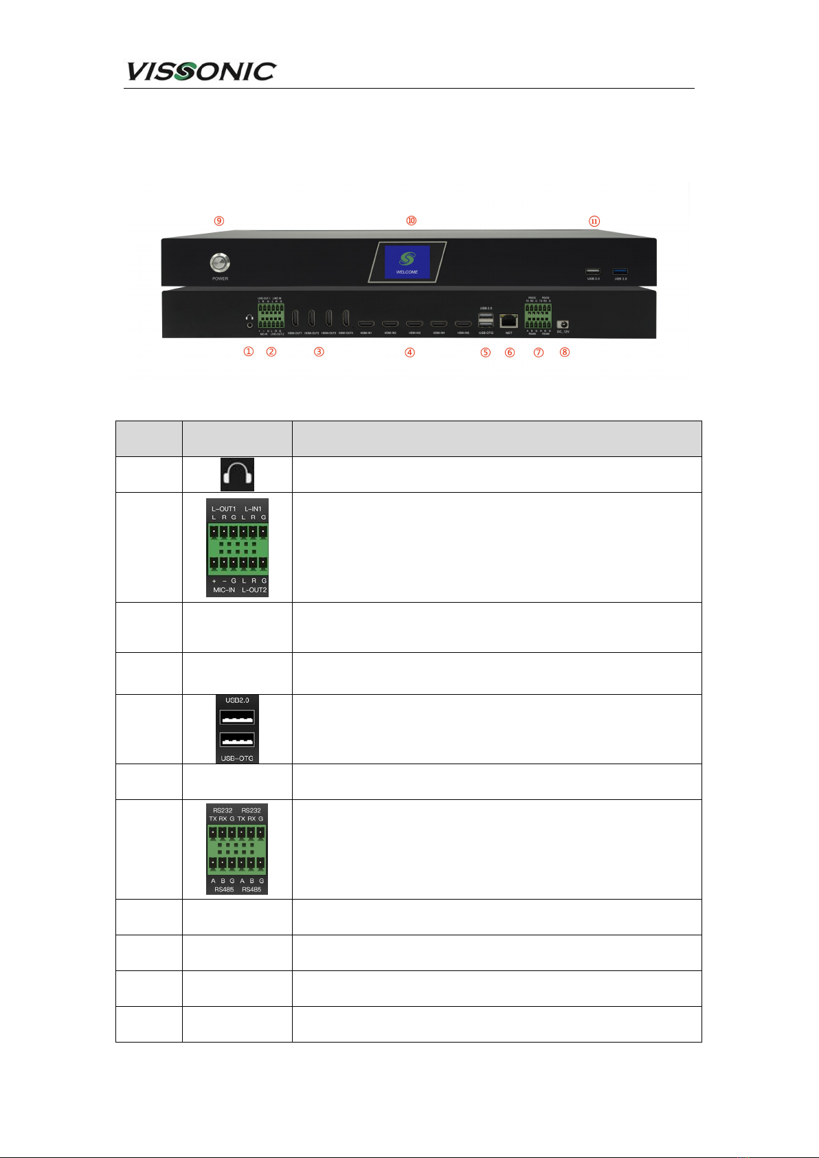
3. Equipment interface description ................................................................................................. 10
4. Host function and operation instructions ......................................................................................11
4.1. Start up ............................................................................................................................... 11
4.2. Start-up guide screen ..........................................................................................................11
4.3. Record (video and audio) ................................................................................................... 11
4.4. Push the current (e.g. in mechanics) ..................................................................................12
4.5. Interactivity .......................................................................................................................12
4.6. Demerger ............................................................................................................................ 14
4.7. Especially efficacious ........................................................................................................ 15
4.8. Guide mode switching ....................................................................................................... 16
4.9. PTZ .....................................................................................................................................16
4.10. Remotely .......................................................................................................................... 17
4.10.1. Resource channel .................................................................................................. 18
4.11. One-touch start ................................................................................................................. 19
5. System function ............................................................................................................................ 20
5.1. (communications) Channel ................................................................................................ 20
5.1.1. Local channel ..........................................................................................................21
5.1.1.1. PTZ operation ..............................................................................................22
5.1.1.2. Head setup ...................................................................................................23
5.1.1.3. Image settings ............................................................................................. 24
5.1.1.4. Code setting ................................................................................................ 24
5.1.2. Remote access ......................................................................................................... 26
5.1.3. PGM ........................................................................................................................28
5.1.4. Window order ...........................................................................................................30
5.2. Set up ................................................................................................................................. 30
5.2.1. Recording setup ..................................................................................................... 31
5.2.1.1. Audio encoding .................................................................................................... 31
5.2.1.5. File upload ...................................................................................................34
5.2.1.6. One click to start configuration ................................................................... 35
5.2.1.7. MQTT (an omission).................................................................................36
5.2.2. Guide settings ......................................................................................................... 36
5.2.2.1. Title setting ................................................................................................. 36
5.2.2.2. Label setting ................................................................................................37
5.2.2.4. Subtitle settings ............................................................................................39
5.2.3. Live streaming settings ......................................................................................... 39
5.2.3.1. RTMP push-stream setting ................................................................... 40
5.2.4. Management platform ............................................................................................ 40
5.2.5. Users and Login ......................................................................................................41
5.2.5.1. User management ......................................................................................... 41
5.2.5.2. Login options ...............................................................................................42

www.vissonic.com
7
5.2.6. Date and time ..........................................................................................................42
5.2.7. Disk and storage .....................................................................................................43
5.2.8. Networks and services ........................................................................................... 44
5.2.8.1. Ethernet ........................................................................................................44
5.2.8.2. Network test ................................................................................................45
5.2.9. Engineering settings ...............................................................................................45
5.2.10. Installation and Commissioning ........................................................................... 46
5.2.10.1. Tracking machine .......................................................................................46
5.2.10.2. Central control settings ............................................................................ 47
5.2.10.3. Anchor keyboard ....................................................................................... 48
5.3. Safeguard ........................................................................................................................... 48
5.3.1. Restore the factory ................................................................................................. 49
5.3.2. Time-lapse video recording ...................................................................................49
5.3.3. Configuration import and export .......................................................................... 50
5.3.4. System information ............................................................................................... 51
5.4. File manager ....................................................................................................................... 51
5.5. Teaching information ........................................................................................................52
5.6. Conference ......................................................................................................................... 52
5.6.1. Platforms & Accounts .............................................................................................53

www.vissonic.com
8
1. Product description
With the gradual popularization of camera video signal source resolution from 1080p
high-definition to 4k resolution (3840x2160), the demand for 4k encoding, recording, live
broadcast and on-demand is increasing. For this reason, our company has launched a 4K
conference recording and broadcasting system solution.
VIS-CRS05-B is an integrated recording and broadcasting device integrating courseware
recording, live broadcast, on-demand, intelligent broadcasting, storage and other functions. Based
on the ARM architecture design, the product has powerful performance. The VIS-CRS05-B adopts
H.265 encoding and supports 5-channel 4K video signal acquisition and encoding. From
acquisition, recording to output, all support 4K resolution. Support synchronous recording and live
broadcast in movie mode + resource mode, PGM screen supports picture-in-picture, 1/2/3/4//6
split screen mode display and recording.

www.vissonic.com
9
2. Specification parameter table
Model
VIS-CRS05-B
video input
5 HDMI signal input
video output
4 HDMI signal output
Maximum Input
Resolution
3840x2160@30fps
Maximum output
resolution
3840x2160@30fps
Audio input
1 balanced input,3pin Phoenix terminal interface
1 unbalanced input,3.5mm interface
Audio output
1 Balanced output,3pin Phoenix terminal
1 Unbalanced listening output interface,3.5mm Earphone hole
video encoding
H.264,H.265
audio coding
AAC
Video output format
MP4
Video encoding
frame rate
1~30fps
Video bitrate
500kbps~40Mbps Can be adjusted
Audio bitrate
8~128KB Can be adjusted
Data Storage
built-in 1T hard drive,Support extension
RS485
2 groups3pin Phoenix terminal Connector
RS232
2 groups3pin Phoenix terminal Connector
network
1 1000M network port,RJ-45
USB interface
2 USB2.0,1 USB3.0,1 USB_OTG
software upgrading
Support for network upgrades、OTG upgrade
Storage mode
Support for built-in hard drives、External USB storage,Supports USB
export,Support for FTP download
protocol support
RTMP、RTSP、UDP、TCP、FTP、DHCP、HTTP
Working power
supply
DC 12V/3A
Equipment size
1U rackmount

www.vissonic.com
10
3. Equipment interface description
Number
Interface
Identification
Illustration
1
3.5mm headphone monitor jack
2
L-IN1:Unbalanced audio input,Phoenix Terminal Connector
MIC-IN:Balanced Audio Input,Phoenix Terminal Connector
L-OUT1:Unbalanced audio input,Phoenix Terminal Connector
L-OUT2:Unbalanced audio input,Phoenix Terminal Connector
3
HDMI OUT 1-4
HDMI signal output,The output screen is a guide screen or a PGM.
(Software can be set)
4
HDMI IN 1-5
HDMI signal input,Support 5-channel 4K video signal input at the
same time
5
USB 2.0:
For external removable storage media for copying files or
mouse operations
USB-OTG:For software upgrades
6
NET
Gigabit network interface,For device networking
7
RS 232:For external guide keyboard, centre control, etc.
L-OUT1:For external guide keyboard, centre control, etc.
L-OUT2:For external guide keyboard, centre control, etc.
8
DC-12V
Device Power Interface,Equipped with 12V 3A power adapter
9
POWER
Equipment power switch
10
LCD screen
For recording status, channel status, network information, storage
space, and logo display
11
USB
USB 2.0*1,USB 3.0*1, For external removable storage media for
copying files or mouse operations

www.vissonic.com
11
4. Host function and operation instructions
4.1. Start up
After the equipment power cord is connected (DC12V/1A ) , Press the unit's power
on/off button
4.2. Start-up guide screen
The main interface of the guide includes "live screen (PGM/PGM2)", "resource channel
preview", "guide" function, "PTZ", "remote", "one key start", "menu" and other options.
Click the hover button on the recording interface to switch between the recording
interface and the screen of the PC accessing the recording (see the Installation Guide for
details).
This is a page up/down button. When there are multiple preview channels, click it to
flip the preview.
4.3. Record (video and audio)
Click "Start" button on the main interface of the software, there will be a "video countdown 5s",
wait for the end of the countdown, then start to record PGM composite images, at the same time,

www.vissonic.com
12
the "Start" icon will turn red, click "Start" icon again will pause the recording. At the same time,
the "Start" icon will turn red, click "Start" icon again to pause the recording. Clicking the "Stop"
button will end the recording task.
Resource Channel Recording (need to record teacher/student/student camera, PC computer
images) can be done by ticking the channels that need to be recorded in
"Menu>Settings>Recording Settings>Recording Policies>Resource Mode" and clicking
Record.
Video files can be viewed in "Menu→File Manager", and can be copied (copied and pasted)
by inserting a USB stick into the recording host.
4.4. Push the current (e.g. in mechanics)
Click "Living" button in the main interface, you can push stream for RTMP and TS, if the push
stream icon will turn red, click "Living" button again to end the push stream.
RTMP push stream need to be set in the "Menu → Settings → Live Settings → RTMP Push
Stream" menu, open the "live on, release mode with the default is Live, open the main stream or
sub-stream, set up to push the stream address, and then go back to the guide home page and click
on the "Push Stream", the icon becomes red that is to push the stream successfully.
4.5. Interactivity
Click on the main screen to go to the figure below, the interactive login screen:
Interactive login screen

www.vissonic.com
13
Enter the account number and password, the account number and password need to be authorised
to open, please contact our sales staff.
Interactive classroom selection screen
Select the classroom, as shown above, to enter based on the classroom name set by the interactive
system;
Presenter interactive interface
When you enter the room, as shown above, the teacher in the main classroom switches the lens of
the listening classroom by clicking on 。
By clicking on , the teacher in the main classroom is asking the listening end to speak, and
clicking on himself or herself to mute.

www.vissonic.com
14
Click to send the PC's screen to the remote end.
Click to start recording, click to start push stream, and click
to return to the guide screen.
Click to enter the menu and to exit the room.
4.6. Demerger
There is a "Split" menu shortcut button on the upper right of the main interface, and the default
guide interface displays three shortcut icons at the same time. ,In manual mode,
you can switch the split screen operation. Click the "Division"
button to enter the selection menu to modify the 3 split screen modes displayed in the
guide interface. The device supports up to 6 split screens, and the position display of A/B/C/D/E/F
can be customised. Click the Split button to enter the shortcut setting customisation.
As shown in the figure below:
Segmentation type

www.vissonic.com
15
where is a custom split option,Click to enter the custom setting
interface, as shown below:
When used with an electronic gantry camera, the system provides
four splits by default to facilitate quick screen
splits for teacher close-ups, student panoramas, and pc screens.
4.7. Especially efficacious
You can set the switching effects during manual and full-automatic playback, which can be used to
smooth the transition of image switching and enhance the viewability of the screen. Record and
broadcast support a variety of switching effects, users can set the main interface effects bar to
display three effects buttons, for rapid playback operations. You can only display 3 special effects
icons in the home page of the guide, click the " " button to enter the menu to modify,
commonly used Wipe (erase), Cover (cover), fade in and out , sliding window, etc..

www.vissonic.com
16
Special effects selection
4.8. Guide mode switching
The recording host supports single-click touch resource channel for PGM live channel image
switching in manual guide mode.
Mode switching
In manual guide mode, the camera is not automatically tracked, and all operations can be set
manually by clicking on the settings, such as split screen, special effects, switching to PGM and
other operations.
In semi-automatic guide mode, the tracking camera can automatically track, but you need to
manually click to switch to PGM.
In manual guide mode, the camera is not automatically tracked, and all operations can be set
manually by clicking on the settings, such as split screen, special effects, switching to PGM and
other operations.
Fully automatic and semi-automatic full grey means that this host is not suitable for tracking.
4.9. PTZ
As shown in the figure below, it is used to control the camera's head rotation, zoom and preset
position recall in manual guide Mode.

www.vissonic.com
17
PTZ control
In "Menu→Channel→Remote Channel→(check the channel stream address to be configured)
→Setup→Panel Head→Setup", you can control the camera's up/down/right/left/right rotation and
call the preset position in this interface in manual mode by setting the parameters of the Pan/Tilt
protocol VISCA, the camera's IP address, the camera's port number, the camera's address number,
and so on.
PTZ control
4.10. Remotely
In the Remote menu, you can pull video streams from other cameras (supporting RTSP protocol)
over the network to be displayed on the recording host. If "Teacher/Student Tracking Camera" is
bound in the "eCloud" menu, the teacher/student camera streaming information will be displayed
here.

www.vissonic.com
18
Remote menu
Click the button to enter the Remote Access screen, see "Remote Access" for
details.
4.10.1. Resource channel
Resource channel
As shown in the above figure 6 small video windows are resource channels, in accordance with
the order from top to bottom, from left to right, in order to display the file channel (video on
demand playback channel).
Resource Channel Video:
The recording host supports film mode (PGM/PGM2) + resource channel recording at the same
time, and the recording of the resource channel can be used for post-production non-editing
software. The operation procedure to open the resource channel recording is as follows:
①Tick the resource channel you need to record: Click the main interface
["Menu→Settings→Recording Settings→Recording Policy→Resource Mode] to tick the resource
channel you need to record, as shown in the figure below:

www.vissonic.com
19
②Associated Resource Channel Recording: If you need to record in associated resource mode,
click "Menu→Settings→Recording Settings→Recording Policies" in the main interface to tick the
"RES" menu.
4.11. One-touch start
One button can be associated with "Record", "Push Stream in Movie Mode", "Auto Guide",
"Insert Credits in Movie Mode", "Insert Credits in Movie Mode" and so on. "Auto guide", "Insert
credits into movie mode", "Insert credits into movie" and so on. In the main interface of the guide,
press "Menu>>Setup>>Recording and Broadcasting Settings>>One Click Open Configuration" to
enter the configuration interface, and then click OK to take effect after checking the options that
need to be associated. As shown in the figure below:
One click to start the setup

www.vissonic.com
20
5. System function
As shown in the figure below, click - the main interface [menu], the system functions are
mainly divided into seven modules: 1, "Channel"; 2, "Settings"; 3, "Maintenance"; 4, "Fil
e Manager"; 5, "Teaching Information"; 6, "Conference Settings"; 7, "Interface Switching".
System function
To enter the menu, you need to enter the account password to verify that you can enter the default
account/password are admin. you can also turn off this function, in the "Menu → Settings →
Users and Login → Login Options", turn on the "automatic login" can be.
5.1. (communications) Channel
Channel module
Table of contents
Popular Measuring Instrument manuals by other brands

PCB Piezotronics
PCB Piezotronics IMI SENSORS ICP HT602D11 Installation and operating manual

NAVAC
NAVAC N2A4A user manual

Major tech
Major tech MT920 instruction manual

Diagtools
Diagtools X-431 TSGUN user manual

Edaphic Scientific
Edaphic Scientific ESSAN-10 user manual

ACS
ACS SAF'IR EVOLUTION instruction manual