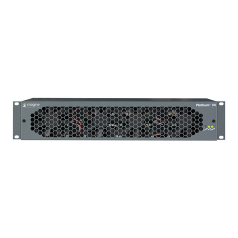
Imagine Platinum IP3 User manual

Platinum™ IP3
28 RU and 15 RU Frame and Modules
September 2016
Edition I
Installation and Operation Manual

Platinum™ IP3 28 RU and 15 RU Frame and Modules Installation and Operation Manual
© 2016 Imagine Communications Corp. Proprietary and Confidential. September 2016 | Page 2
Publication Information
© 2016 Imagine Communications Corp.
Proprietary and Confidential.
Imagine Communications considers this document and its contents to be proprietary and confidential.
Except for making a reasonable number of copies for your own internal use, you may not reproduce this
publication, or any part thereof, in any form, by any method, for any purpose, or in any language other
than English without the written consent of Imagine Communications. All other uses are illegal.
This publication is designed to assist in the use of the product as it exists on the date of publication of
this manual, and may not reflect the product at the current time or an unknown time in the future. This
publication does not in any way warrant description accuracy or guarantee the use for the product to
which it refers. Imagine Communications reserves the right, without notice to make such changes in
equipment, design, specifications, components, or documentation as progress may warrant to improve
the performance of the product.
Trademarks
Platinum™, Platinum™ IP3, Magellan™, Magellan CCS Navigator™ are trademarks or trade names of
Imagine Communications or its subsidiaries.
Microsoft® and Windows® are registered trademarks of Microsoft Corporation. All other trademarks and
trade names are the property of their respective companies.
Contact Information
Imagine Communications has office locations around the world. For domestic and international location
and contact information, visit our Contact page (http://www.imaginecommunications.com/how-
buy/contact-us).
Support Contact Information
For domestic and international support contact information see:
Support Contacts (http://www.imaginecommunications.com/how-buy/contact-us)
Worldwide Support e-mail (mailto: service@imaginecommunications.com)
Customer Community Portal (http://app.imaginecommunications.com/customercommunity)
Warranty & Contract Information (http://www.imaginecommunications.com/services/customer-
care)
MyImagine Academy Training (http://www.imaginecommunications-academy.com)
Product Manuals (http://www.imaginecommunications.com/services/product-manuals)

Platinum™ IP3
Installation and Operation Manual Contents
© 2016 Imagine Communications Corp. Proprietary and Confidential. September 2016 | Page 3
Contents
Preface................................................................................................................. 14
Manual Information ...............................................................................................................................14
Purpose...............................................................................................................................................14
Audience.............................................................................................................................................14
Revision History..................................................................................................................................14
Obtaining Documents.........................................................................................................................15
Unpacking/Shipping Information ...........................................................................................................15
Unpacking a Product ..........................................................................................................................15
Returning a Product ...........................................................................................................................15
Safety......................................................................................................................................................16
Standards................................................................................................................................................16
Waste from Electrical and Electronic Equipment (WEEE) Compliance ..................................................16
Introduction......................................................................................................... 18
Platinum IP3 Overview ...........................................................................................................................18
Product Description............................................................................................................................18
Platinum IP3 28 RU (PX-FR-28) and 15 RU (PX-FR-15) Frames...........................................................18
Features..............................................................................................................................................19
Platinum IP3 Architecture ..................................................................................................................20
Removing the Frame Door .................................................................................................................21
Frame Architecture.................................................................................................................................23
28 RU Platinum IP3 Front View ..........................................................................................................23
15 RU Platinum IP3 Front View ..........................................................................................................24
28 RU Platinum IP3 Rear View............................................................................................................25
15 RU Platinum IP3 Rear View............................................................................................................26
28 RU Platinum IP3 Frame Architecture ............................................................................................27
15 RU Platinum IP3 Frame Architecture ............................................................................................28
Platinum IP3 Physical Specifications ..................................................................................................28
Frame Modules.......................................................................................................................................29
Power Consumption...............................................................................................................................31
Power Consumption of Frame and Input/Output Modules...............................................................31
Platinum IP3 Power and Temperature Specifications........................................................................32
Expansion Overview ...............................................................................................................................33

Platinum™ IP3
Installation and Operation Manual Contents
© 2016 Imagine Communications Corp. Proprietary and Confidential. September 2016 | Page 4
Expansion Setup .................................................................................................................................33
Alarms and LEDs .....................................................................................................................................37
Control Features.....................................................................................................................................37
PoE..........................................................................................................................................................37
Modules............................................................................................................... 38
Modules Overview..................................................................................................................................38
Input and Output Modules.....................................................................................................................38
List of Supported Input and Output Modules....................................................................................39
Rear Connectors .....................................................................................................................................40
Output Rear Connectors.....................................................................................................................40
Input Rear Connectors .......................................................................................................................40
Expansion Modules ............................................................................................................................40
Crosspoint Modules................................................................................................................................ 40
Monitoring Modules...............................................................................................................................41
Output Monitoring Modules ..............................................................................................................41
Multiviewer Modules .........................................................................................................................41
Resource Module (PX-RES) .................................................................................. 42
Resource Module (PX-RES) Overview.....................................................................................................42
PX-RES in a Platinum frame................................................................................................................42
PX-RES Parameters and Upgrades......................................................................................................44
PX-RES Redundancy............................................................................................................................44
Communications Back Panel (PX-CBP) ...............................................................................................45
User Interfaces .......................................................................................................................................46
Ethernet Ports ....................................................................................................................................46
Sync Ports...........................................................................................................................................47
Alarm Port ..........................................................................................................................................48
LTC Bi-Directional Port .......................................................................................................................48
LEDs ....................................................................................................................................................48
Fuses...................................................................................................................................................50
DIP Switches .......................................................................................................................................51
XY Ports ..............................................................................................................................................51
Serial Ports..........................................................................................................................................51
Resource Card Synchronization..............................................................................................................53
Active and Standby Determination ....................................................................................................53
Sync Notes..........................................................................................................................................53
Switch Triggering ....................................................................................................................................54
Alarms.....................................................................................................................................................56
Power Consumption...............................................................................................................................56

Platinum™ IP3
Installation and Operation Manual Contents
© 2016 Imagine Communications Corp. Proprietary and Confidential. September 2016 | Page 5
Installation..............................................................................................................................................56
Alarm Expansion Module (PX-ALARM)................................................................. 57
PX-ALARM Components .........................................................................................................................58
Controlling Fan Speed.............................................................................................................................59
Reporting Alarms and Fan Failures.........................................................................................................59
Power Supply Status........................................................................................................................... 59
Power Supply Zone Redundancy........................................................................................................61
GPI Input Alarms.................................................................................................................................61
GPI Output Alarms (User Configurable Alarms).................................................................................62
Fan Failure Alarm ...............................................................................................................................62
General Purpose Interface (GPI).............................................................................................................63
Micro-Dsub Connector Pinouts..........................................................................................................64
Parameters .............................................................................................................................................64
PX-ALARM-DATA Parameters.............................................................................................................64
PX-ALARM-ATDM Parameters............................................................................................................65
Status and Alarm LEDs............................................................................................................................66
Failsafe Upgrade.....................................................................................................................................66
Power Consumption...............................................................................................................................67
Output Monitoring Modules................................................................................ 68
PX-HSRAEC-OM Output Monitoring Module .........................................................................................68
Notes ..................................................................................................................................................68
Controllable Parameters ....................................................................................................................70
Video Crosspoint Module (PX-576x1024-3G/PX-288x512-3G)............................. 72
28 RU Video Crosspoint Module Location in the Frame ........................................................................74
Extracting the Video Crosspoint from the 28 RU Frame....................................................................75
Putting the Video Crosspoint back into the 28 RU Frame..................................................................78
15 RU Video Crosspoint Module Location in the Frame ........................................................................79
Video Crosspoint Module Parameters ...................................................................................................80
LED Indicators on Video Crosspoint Module..........................................................................................81
Fuses on the Video Crosspoint Module..................................................................................................82
Power Consumption...............................................................................................................................83
Audio TDM Crosspoint Module (PX-ATDM64-X28).............................................. 84
Audio TDM Crosspoint Module (PX-ATDM64-X28) Location in the IP3 Frame......................................86
Fuses on the PX-ATDM64-X28................................................................................................................88
DIP Switches on the PX-ATDM64-X28 ....................................................................................................89
Fans on the Audio TDM Crosspoint Module (PX-ATDM64-X28) ............................................................90

Platinum™ IP3
Installation and Operation Manual Contents
© 2016 Imagine Communications Corp. Proprietary and Confidential. September 2016 | Page 6
Instructions to Replace the Fan Blowers............................................................................................91
Sync References......................................................................................................................................91
PX-ATDM64-X28 Block Diagram.............................................................................................................91
Functionality...........................................................................................................................................92
16/20/24 bit Audio Processing...........................................................................................................92
Transitions..........................................................................................................................................92
Quiet Switching ..................................................................................................................................92
Synchronous Switching ......................................................................................................................92
Asynchronous Signals.........................................................................................................................92
Level Adjustment................................................................................................................................92
Sample Rate Conversion (SRC) ...........................................................................................................92
Tone Generator..................................................................................................................................93
Polarity Reversal.................................................................................................................................93
Channels Swapping and Summing .....................................................................................................93
Redundancy........................................................................................................................................93
Frame Expansion ................................................................................................................................93
LED Indicators.........................................................................................................................................94
Hardware Connections for Audio Expansion..........................................................................................95
Audio Expansion Connection Status in the Web UI................................................................................97
PX-ATDM64-X28 Parameters..................................................................................................................98
Firmware Upgrade..................................................................................................................................99
Power Consumption.............................................................................................................................100
Frame Parameters ............................................................................................. 101
Frame....................................................................................................................................................102
PX-RES...................................................................................................................................................102
Video Crosspoint ..................................................................................................................................104
TDM Crosspoint....................................................................................................................................105
Sync.......................................................................................................................................................105
Sync Notes........................................................................................................................................107
Power Supplies .....................................................................................................................................107
Ethernet Ports ......................................................................................................................................108
Serial Ports............................................................................................................................................110
Input Modules (PX-IB)........................................................................................ 111
PX-IB Input Module General Overview.................................................................................................111
PX-IB Input Options ..........................................................................................................................111
PX-IB Expansion................................................................................................................................112
Inserting Input Modules into the Platinum IP3 frame..........................................................................112
Failsafe Mode ...................................................................................................................................113

Platinum™ IP3
Installation and Operation Manual Contents
© 2016 Imagine Communications Corp. Proprietary and Confidential. September 2016 | Page 7
Signal Presence and LEDs .....................................................................................................................113
Module LEDs.....................................................................................................................................113
System LEDs......................................................................................................................................113
Controllable Parameters.......................................................................................................................115
Parameter Notes ..............................................................................................................................115
(Module) Root Level Parameters .....................................................................................................115
Input Parameters..............................................................................................................................116
Specifications........................................................................................................................................119
Technical Specifications ...................................................................................................................119
Capacity............................................................................................................................................119
Output Modules (PX-OB) ................................................................................... 120
PX-OB Output Module General Overview............................................................................................120
PX-OB Output Options......................................................................................................................120
PX-OB Expansion ..............................................................................................................................121
Inserting Output Modules into the Platinum IP3 frame.......................................................................121
Failsafe Mode ...................................................................................................................................121
Signal Presence and LEDs .....................................................................................................................122
System LEDs......................................................................................................................................122
Module LEDs.....................................................................................................................................123
Controllable Parameters.......................................................................................................................123
Parameter Notes ..............................................................................................................................123
(Module) Root Level Parameters .....................................................................................................124
Output Parameters...........................................................................................................................125
Specifications........................................................................................................................................126
Technical Specifications ...................................................................................................................126
Capacity............................................................................................................................................127
Digital Video Modules........................................................................................ 128
PX-HSR9C-IBG Input Module ................................................................................................................129
Power Consumption.........................................................................................................................129
PX-HSR9O-IBG Input Module................................................................................................................129
Power Consumption.........................................................................................................................130
PX-HSR9C-IBG/PX-HSR9O-IBG Parametric Control ..........................................................................130
PX-HSR9C1D-IBG Input Module............................................................................................................131
Power Consumption.........................................................................................................................131
PX-HSR9O1D-IBG Input Module ...........................................................................................................131
Power Consumption.........................................................................................................................132
PX-HSR1C1D-IBG Input Module............................................................................................................132
Power Consumption.........................................................................................................................132

Platinum™ IP3
Installation and Operation Manual Contents
© 2016 Imagine Communications Corp. Proprietary and Confidential. September 2016 | Page 8
PX-HSR16C-OBG Output Module .........................................................................................................133
Power Consumption.........................................................................................................................133
PX-HSR16O-OBG Output Module.........................................................................................................134
Power Consumption.........................................................................................................................134
PX-HSR16C-OBG/PX-HSR16O-OBG-IBG Parametric Control ............................................................134
PX-HSR8O2D-OBG Output Module ......................................................................................................135
Power Consumption.........................................................................................................................135
PX-HSR8C2D-OBG Output Module.......................................................................................................136
Power Consumption.........................................................................................................................136
PX-HSR8C2D-OBG/PX-HSR8O2D-OBG Parametric Control ..............................................................137
PX-HSR1D2D-OBG Output Module.......................................................................................................137
Power Consumption.........................................................................................................................138
PX-HSR1D2D-OBG Output Module...................................................................................................138
PX-UCIP Uncompressed Video over IP Modules................................................. 139
Frame Synchronizer and Demultiplexing Input Modules (PT-FSDMX-IBG/PT-
FSDMXO-IBG, PT-FSDX8C1D-IBG, PT-FSDMX8O1D-IBG)..................................... 140
Back Module Variants...........................................................................................................................141
Electrical/BNC Back Module (PT-FSDMX-IBG)..................................................................................142
Optical/SFP Back Module (PT-FSDMXO-IBG) ...................................................................................142
Electrical Back Module (HD-BNC) with DensiShield (PT-FSDX8C1D-IBG).........................................143
Optical Back Module (SFP) with DensiShield (PT-FSDX8O1D-IBG)...................................................144
Specifications........................................................................................................................................144
Equalization Information for PT-FSDX8C1D-IBG ..............................................................................145
Video Processing Features....................................................................................................................146
Video Processing Notes....................................................................................................................146
Audio Processing Features ...................................................................................................................147
Audio Processing Notes and Restrictions.........................................................................................147
Audio Order of Operations...............................................................................................................147
Sample Rate Conversion...................................................................................................................148
Quiet Audio Transitions....................................................................................................................148
PT-FSDMX-IBG Licensing.......................................................................................................................148
PT-FSDMX-IBG without Frame Sync Option.....................................................................................148
PT-FSDMX-IBG with Frame Sync Option ..........................................................................................149
PT-FSDMX-IBG Controllable Parameters..............................................................................................150
General Parameters .........................................................................................................................150
Genlock Parameters .........................................................................................................................151
Input Parameters..............................................................................................................................151
Notes ................................................................................................................................................156

Platinum™ IP3
Installation and Operation Manual Contents
© 2016 Imagine Communications Corp. Proprietary and Confidential. September 2016 | Page 9
LED Indicators.......................................................................................................................................160
Power-Up sequence .............................................................................................................................160
Firmware Upgrade and Backup Image .................................................................................................161
PX-HSRMX-OBG Frame Sync and Mux Output Module ...................................... 162
PX-HSR8CMX8C-OBG Electrical Output Module ..............................................................................163
PX-HSR8OMX8O-OBG Optical Output Module ................................................................................163
PX-HSRMX8C2D-OBG Electrical Module with DensiShield ..............................................................163
PX-HSRMX8O2D-OBG Optical Module with DensiShield .................................................................164
PX-HSRMX-OBG Operation Modes.......................................................................................................164
MUX only mode (without Frame Sync license) ................................................................................164
Frame Sync Mode.............................................................................................................................165
PX-HSRMX-OBG Features .....................................................................................................................166
Audio Processing ..............................................................................................................................167
Video Processing ..............................................................................................................................168
Quiet Audio Switching......................................................................................................................169
PX-HSRMX-OBG Specifications.............................................................................................................170
Electrical Output (Back Module with 16 HD-BNCs)..........................................................................170
Electrical Output (Back Module with DensiShield) ..........................................................................170
Optical Output (Fiber Back Modules with SFPs) ..............................................................................171
Electrical Input (Back Module with DensiShield) .............................................................................171
PX-HSRMX-OBG Operation...................................................................................................................171
Power-Up Sequence.........................................................................................................................171
Firmware Upgrade and Backup Image.............................................................................................171
LED Indicators...................................................................................................................................172
Jumpers and DIP Switches................................................................................................................172
Failsafe Module Upgrade .................................................................................................................172
Power Consumption.........................................................................................................................172
Functional Block Diagram.................................................................................................................173
PX-HSRMX-OBG Controllable Parameters............................................................................................174
General Parameters .........................................................................................................................174
Genlock Parameters .........................................................................................................................175
Processed Outputs ...........................................................................................................................176
Unprocessed Outputs.......................................................................................................................183
Notes: ...............................................................................................................................................184
Multichannel Audio Digital Interface (MADI) Modules ...................................... 191
MADI Input Module (PT-MADI4X-IBG).................................................................................................192
Variants ............................................................................................................................................193
Controlling the MADI Input Module through the Controller...........................................................194

Platinum™ IP3
Installation and Operation Manual Contents
© 2016 Imagine Communications Corp. Proprietary and Confidential. September 2016 | Page 10
TDM Mapping...................................................................................................................................195
MADI Audio Formats........................................................................................................................198
Input Specifications..........................................................................................................................200
Input Power Consumption ...............................................................................................................200
PT-MADI4X-IBG Parameters.............................................................................................................201
MADI Output Module PT-MADI4X-OBG...............................................................................................203
Variants ............................................................................................................................................203
Controlling the MADI Output Module through the Controller ........................................................ 205
Reference Locking ............................................................................................................................205
TDM Input.........................................................................................................................................206
TDM Output Mapping ......................................................................................................................207
Output Specifications .......................................................................................................................207
Output Power Consumption ............................................................................................................208
PT-MADI4X-OBG Parameters ...........................................................................................................208
Analog/Digital Audio Converter Modules with TDM .......................................... 212
Audio A/D Input Modules with TDM Capability (PT-ADCT-IB) .............................................................212
Operation .........................................................................................................................................212
Installation........................................................................................................................................215
Control..............................................................................................................................................215
Controllable Parameters ..................................................................................................................215
Functional Block Diagram.................................................................................................................218
Pinout Diagram.................................................................................................................................219
Specifications....................................................................................................................................219
Power Consumption.............................................................................................................................221
AES to Analog Audio Converter Output Modules with TDM Capability (PT-DACT-OB) .......................222
Operation .........................................................................................................................................222
Installation........................................................................................................................................223
Control..............................................................................................................................................223
Controllable Parameters ..................................................................................................................224
Functional Block Diagram.................................................................................................................226
Pinout Diagram.................................................................................................................................227
Specifications....................................................................................................................................228
Power Consumption.............................................................................................................................229
AES Balanced/Coaxial Modules with TDM Capability......................................... 230
AES Balanced/Coaxial Input Modules with TDM Capability (PT-AEBT-IB/PT-AECT-IB) ........................230
Operation .........................................................................................................................................230
Installation........................................................................................................................................232
Control..............................................................................................................................................232

Platinum™ IP3
Installation and Operation Manual Contents
© 2016 Imagine Communications Corp. Proprietary and Confidential. September 2016 | Page 11
Controllable Parameters ..................................................................................................................233
Functional Block Diagram.................................................................................................................234
Pinout Diagram.................................................................................................................................235
Specifications....................................................................................................................................236
Power Consumption.........................................................................................................................237
AES Balanced/Coaxial Output Modules with TDM Capability(PT-AEBT-OB/PT-AECT-OB)...................237
Operation .........................................................................................................................................237
Installation........................................................................................................................................239
Control..............................................................................................................................................239
Controllable Parameters ..................................................................................................................240
Functional Block Diagram.................................................................................................................241
Pinout Diagram.................................................................................................................................242
Specifications....................................................................................................................................243
Power Consumption.........................................................................................................................244
Analog Composite Video Modules..................................................................... 245
Analog Video to SDI Decoder Input Modules (PT-DEC-IB) ...................................................................245
Operation .........................................................................................................................................245
Installation........................................................................................................................................247
Control..............................................................................................................................................247
Controllable Parameters ..................................................................................................................247
Functional Block Diagram.................................................................................................................249
Specifications....................................................................................................................................249
Power Consumption.............................................................................................................................250
SD to Analog Video Encoder Modules (PT-ENC-OB).............................................................................250
Operation .........................................................................................................................................250
Installation........................................................................................................................................251
Control..............................................................................................................................................252
Controllable Parameters ..................................................................................................................252
Functional Block Diagram.................................................................................................................254
Specifications....................................................................................................................................255
Power Consumption.............................................................................................................................255
Platinum SX Hybrid Multiviewer Modules.......................................................... 256
Platinum SX Hybrid Modules in 15/28 RU Frames ...............................................................................258
Platinum SX Hybrid Back Module.........................................................................................................259
Inserting Platinum SX Hybrid Modules into a Frame ...........................................................................260
Configuring the Platinum SX Hybrid Module........................................................................................261
Platinum SX Pro Multiviewer Modules............................................................... 262

Platinum™ IP3
Installation and Operation Manual Contents
© 2016 Imagine Communications Corp. Proprietary and Confidential. September 2016 | Page 12
1500 Watt Power Supply and External Power Supply Frame ............................. 263
Power Supplies (PX-PS).........................................................................................................................263
Power Supply Modes........................................................................................................................264
Power Supplies in a 28 RU Frame.....................................................................................................264
Power Supplies in a 15 RU Frame.....................................................................................................265
External Power Supply Frame (PX-FR-EXPS).........................................................................................265
Required Equipment ........................................................................................................................266
Power Cables....................................................................................................................................266
Power Cable Installation Steps (for PX-FR-EXPS to PX-FR-28/PX-FR-15) .........................................266
Installing Power Supplies......................................................................................................................270
Power Zones .........................................................................................................................................272
Power Zones for a 28 RU Frame.......................................................................................................272
Power Zones for a 15 RU Frame.......................................................................................................274
Power Distribution Zones.................................................................................................................275
Power Distribution Modules ................................................................................................................277
Top Power Distribution Module (PX-PD-TOP)..................................................................................277
Bottom Power Distribution Module (PX-PD-BOT)............................................................................280
Power Supply Specs, LEDs, and Pinouts ...............................................................................................281
Power Supply Mechanical Specification...........................................................................................281
Power Supply Electrical Specification...............................................................................................282
Power Supply LED Operation ...........................................................................................................283
Power Connector Pinout ..................................................................................................................284
PX-FRONT-FAN and PX-REAR-FAN Modules....................................................... 285
Front Fan Module.................................................................................................................................285
Front Fan LEDs..................................................................................................................................287
Front Fans Status in the Web UI.......................................................................................................289
Rear Fan Module ..................................................................................................................................289
Rear Fans Status in the Web UI........................................................................................................291
Servicing the Fans.................................................................................................................................291
Replacing a Front Fan Module .........................................................................................................291
Replacing an Individual Front Fan ....................................................................................................293
Replacing a Rear Fan ........................................................................................................................294
Fuses.....................................................................................................................................................295
Fuses on Front Fan Modules ............................................................................................................295
Fuses on Rear Fan Adapter Boards ..................................................................................................296
Power Consumption.............................................................................................................................297
Module LEDs...................................................................................................... 298
Card Edge LED Diagnostics ...................................................................................................................298

Platinum™ IP3
Installation and Operation Manual Contents
© 2016 Imagine Communications Corp. Proprietary and Confidential. September 2016 | Page 13
LED Labels.........................................................................................................................................298
LED States.........................................................................................................................................298
Input Module LEDs ...............................................................................................................................299
Input 1 and Input 2...........................................................................................................................299
Input 3, Input 4, Input 5 ...................................................................................................................299
Input 6, Input 7, Input 8, Input 9......................................................................................................299
Output Module LEDs ............................................................................................................................300
Output 1 - Output 6..........................................................................................................................300
Output 7, Output 8, Output 9...........................................................................................................300
Output 13, Output 14, Output 15, Output 16..................................................................................300
Module Interconnect (PX-BP-28/PX-BP-15) ....................................................... 302
PX-BP-28/PX-BP-15 Module Slots.........................................................................................................302
Fuses on the Module Interconnect (PX-BP-28) ....................................................................................303
Fuses on the Module Interconnect (PX-BP-15) ....................................................................................307
Module Interconnect Installation.........................................................................................................309
Auxiliary Module (PX-AUX)................................................................................. 310
PX-AUX Fuses........................................................................................................................................311
PX-AUX Block Diagram.......................................................................................................................... 312
Sync Module Interconnect (PX-SYNC-MI)........................................................... 313
Power Adapter Module (PX-PWR-ADPTR).......................................................... 314
Fuses on the Power Adapter PX-PWR-ADPTR......................................................................................315

Platinum™ IP3
Installation and Operation Manual Preface
© 2016 Imagine Communications Corp. Proprietary and Confidential. September 2016 | Page 14
Preface
Manual Information
Purpose
This manual details the features, installation, operation, maintenance, and specifications for the
Platinum IP3.
Audience
This manual is written for engineers, technicians, and operators responsible for installation, setup,
maintenance, and/or operation of the Platinum IP3.
Revision History
Edition
Date
Comments
A
December 2012
Preliminary Version
B
January 2013
First Release
C
October 2014
Third Release
D
February 2015
Support for PX-RES in Platinum 5 RU and 9 RU Frames.
See PX-RES in a Platinum frame (on page 42)
E
October 2015
New 15 RU Platinum IP3 frame
F
December 2015
Minor edits to add PoE warning. See PoE (on page 37).
G
March 2016
Added info on the Platinum SX Hybrid Module. See
Platinum SX Hybrid Multiviewer Modules (on page 255)
H
June 2016
Audio Expansion support. See Audio Expansion (on
page 36) and Hardware Connections for Audio
Expansion (on page 95)
Updates to firmware upgrade procedure for the PX-
ATDM64-x28 module. See Firmware Upgrade (on
page 99)
I
September 2016
New PX-UCIP Module. See PX-UCIP Uncompressed
Video Over IP Modules (on page 139)
New PX-HSR1D2D-OBG DensiShield Feeder Module.
See PX-HSR1D2D-OBG Output Module (on page 137)

Platinum™ IP3
Installation and Operation Manual Preface
© 2016 Imagine Communications Corp. Proprietary and Confidential. September 2016 | Page 15
Obtaining Documents
Product support documents can be viewed or downloaded from our website. Alternatively, contact your
Customer Service representative to request a document.
Unpacking/Shipping Information
Unpacking a Product
This product was carefully inspected, tested, and calibrated before shipment to ensure years of stable
and trouble-free service.
1. Check equipment for any visible damage that may have occurred during transit.
2. Confirm that you have received all items listed on the packing list.
3. Contact your dealer if any item on the packing list is missing.
4. Contact the carrier if any item is damaged.
5. Remove all packaging material from the product and its associated components before you install
the unit.
Keep at least one set of original packaging, in the event that you need to return a product for servicing.
Returning a Product
In the unlikely event that your product fails to operate properly, please contact Customer Service to
obtain a Return Authorization (RA) number, and then send the unit back for servicing.
Keep at least one set of original packaging in the event that a product needs to be returned for service.
If the original package is not available, you can supply your own packaging as long as it meets the
following criteria:
The packaging must be able to withstand the product’s weight.
The product must be held rigid within the packaging.
There must be at least 2 in. (5 cm) of space between the product and the container.
The corners of the product must be protected.
Ship products back to us for servicing prepaid and, if possible, in the original packaging material. If the
product is still within the warranty period, we will return the product prepaid after servicing.

Platinum™ IP3
Installation and Operation Manual Preface
© 2016 Imagine Communications Corp. Proprietary and Confidential. September 2016 | Page 16
Safety
This manual contains safety precautions and recommendations specific to the IP3 frame. The IP3 is rack-
mountable using rack rails provided with the unit, and it is strongly recommended to do so. See the
specifications section for the electrical current load of the product, and connect the redundant power
supplies to electrical circuits which are each capable of supplying the full load of the unit. The IP3 is
forced-air cooled; to prevent marring during handling and transit there are clear plastic coatings which
cover the metallic surfaces and obstruct some of the air ventilation holes. Be sure to remove all of these
clear plastic coatings before putting the unit into service.
IMPORTANT! Only qualified personnel should perform service procedures.
Table 1: Safety Terms and Symbols in this Manual
WARNING
Statements identifying conditions or practices that may result in
personal injury or loss of life. High voltage is present.
CAUTION
Statements identifying conditions or practices that can result in
damage to the equipment or other property.
Standards
Refer to the IP3 Safety and Standards Manual for details.
Waste from Electrical and Electronic
Equipment (WEEE) Compliance
The European Union (EU) Directive 2002/96/EC on Waste from Electrical and Electronic Equipment
(WEEE) deals with the collection, treatment, recovery, and recycling of electrical and electronic waste
products. The objective of the WEEE Directive is to assign the responsibility for the disposal of
associated hazardous waste to either the producers or users of these products. As of August 13, 2005,
the producers or users of these products were required to recycle electrical and electronic equipment at
end of its useful life, and may not dispose of the equipment in landfills or by using other unapproved
methods. (Some EU member states may have different deadlines.)

Platinum™ IP3
Installation and Operation Manual Preface
© 2016 Imagine Communications Corp. Proprietary and Confidential. September 2016 | Page 17
In accordance with this EU Directive, companies selling electric or electronic devices in the EU will affix
labels indicating that such products must be properly recycled. (See our website for more information.)
Contact your local sales representative for information on returning these products for recycling.
Equipment that complies with the EU directive will be marked with a WEEE-compliant emblem.
Figure 1: WEEE Compliance Emblem

Platinum™ IP3
Installation and Operation Manual Introduction
© 2016 Imagine Communications Corp. Proprietary and Confidential. September 2016 | Page 18
Introduction
Platinum IP3 Overview
The Platinum IP3™ Intelligent Signal Routing System provides unprecedented scalability and flexibility to
designers of new broadcast facilities, OB production vehicles, and other television switching, monitoring,
and transmission facilities worldwide.
The Platinum IP3 features enhanced crosspoint and switching architectures which allow scalability to
extremely large systems, coupled with a new frame design for improved density and reliability in large
system configurations.
The Platinum IP3 Router is available in the following frame sizes:
28 RU (PX-FR-28) frame supporting matrices up to 576x1024
15 RU (PX-FR-15) frame supporting matrices up to 288x512
Product Description
The Platinum IP3 routing switcher system extends both the matrix size and functionality of Imagine
Communications' routing switcher product line. Its flexible modular architecture accommodates
standard definition, high definition, and 1080p digital video signals while keeping a versatile frame and
control system. This combination allows high performance, multi-format video, audio and embedded
audio routing within a single, flexible frame.
The Platinum IP3 routing switcher system provides video matrix expandability (9x16) to 576×1024 in a
single 28 RU frame or 288x512 in a single 15 RU frame. The 9×16 building block provides ideal growth
and flexibility for mixed applications such as high definition and serial digital interface, and other
integrated processing opportunities such as analog and/or digital conversion. With its ability to route
signals ranging from 3.0 Mb/s to 2.97 Gb/s, the IP3 router offers a clear growth path from lower bit rate
signals to high bandwidth, high definition format signals. This router will also handle both AES and
polarity sensitive ASI/SSI signal formats.
Platinum IP3 28 RU (PX-FR-28) and 15 RU (PX-FR-15) Frames
The flagship frame in the Platinum IP3 system is a 28RU frame, featuring 576 wideband video inputs
distributed across 64 modular slots, and 1024 wideband video outputs distributed across 64 modular
slots. This can expand to 1152x1024 in two 28RU frames, while providing 2N redundant crosspoint (XPT)
modules. See Video Matrix Expansion.
The 28RU Platinum IP3 frame provides a large matrix size via new crosspoint (XPT) modules, a new
backplane (MI), and new Input/Output (I/O) modules. A new resource module (PX-RES) provides greater
processing capacity, and an upgraded version of the Platinum TDM crosspoint module allows for the
increased matrix capacity.

Platinum™ IP3
Installation and Operation Manual Introduction
© 2016 Imagine Communications Corp. Proprietary and Confidential. September 2016 | Page 19
The Platinum IP3 15 RU is a compact version of the larger Platinum IP3 28 RU high-performance router,
delivering the same integrated routing and processing capabilities in a space-saving 288x512 form
factor. This provides mobile and other production environments with significant cost-, space- and
power-efficiency improvements.
The 15RU Platinum IP3 frame features 288 wideband video inputs distributed across 32 modular slots,
and 512 wideband video outputs distributed across 32 modular slots. This can expand to 576x512 across
two 15 RU frames, while providing 2N redundant crosspoint (XPT) modules. See Video Matrix
Expansion.
Both (15 RU and 28 RU) frames use common, front-loadable, and hot-swappable input and output
modules. The Platinum IP3 frames use unique Video and Audio Crosspoint modules which are not
compatible with Platinum frames. The frame has a passive module interconnect (MI) signal distribution
module interconnecting the routing system.
The frame is accessible from the front via a removable door. Status LEDs can be viewed through this
door; these LEDs indicate power supply presence (and status), resource module usage, and link light
indicators for Ethernet communications ports. Four 1500 watt power supplies are present. Frames with
conversion or advanced processing options may require additional power supplies; or additional power
supplies may be added for redundancy.
Status LEDs on Power Supply units, Resource cards, and various I/O modules are visible when the door is
open. Alarms on various modules are reported to the Platinum IP3 Controller to ease hardware
management of the system.
The Platinum IP3 frame is designed to be compliant with NEBS certification requirements (for example,
module retention doors, non-removable door option, locking power supplies, etc.). The frame is
compatible with router control software products such as Magellan CCS Navigator and can also be
controlled via a web based Controller.
Features
Routing for Large Systems
576x1024 in a single 28RU frame
1152x1024 in two 28RU frames
576x2048 in two 28RU frames
1152x2048 in four 28RU frames
1152x3072 in six 28RU frames
Video Routing
HD-SDI digital multirate from 3.00 Mb/s to 2.97 Gb/s
Digital video signals including SMPTE 310, SDI, ASI, HD-SDI
Analog video via conversion to/from SDI on I/O modules

Platinum™ IP3
Installation and Operation Manual Introduction
© 2016 Imagine Communications Corp. Proprietary and Confidential. September 2016 | Page 20
Audio Routing
Digital audio signals including balanced and unbalanced (coaxial) AES
Analog stereo audio via conversion to/from AES on I/O modules
MADI audio - Embedded audio with the use of Audio De-multiplexing and Multiplexing boards
Module I/O in groups of 8 or 9 inputs and 8 or 16 outputs
Route to/from digital and analog signals with no external processing
Front-loading, hot swappable modules
Redundancy (power supplies, resource modules, signal paths) throughout
Enhanced control and monitoring capabilities
Secure access rights with restrictions by level, source, and destination
CCSP, SNMP, and third-party protocol support
Platinum IP3 Architecture
The Platinum IP3's flexible modular architecture accommodates standard definition, high definition, and
1080p digital video signals while keeping a versatile frame and control system. This combination allows
high performance, multi-format video, audio, and embedded audio routing within a single, flexible
frame. The IP3 can switch signals from 3 Mb/s to 3Gb. It can pass and reclock SD-SDI (including 143, 177,
270, 360, and 540 Mb/s), HD-SDI (1.485 Gb/s), as well as 3G-SDI signals, supporting routing of SD/HD/3G
signals in the same router.
The Platinum wideband video and audio TDM switching fabrics (which allow for non-blocking audio
processing) have been retained.
To support audio matrix expansion between two IP3 frames, the internal Audio Time Division
Multiplexed (TDM) buses are Time-division multiplexed onto a higher speed TDM bus operating at 3
Gbits/s each and carried over 16 DensiShield channels. This requires a minimum of two DensiShield
cables –one for outputs distribution and a second for input distribution or four cables if redundancy is
desired. With the Platinum IP3's Audio Expansion option, a two frame system is fully non-blocking,
meaning that audio inputs (embedded or discrete) in frame one can be routed to any output in frame
two.
Table of contents
Other Imagine Network Router manuals
Popular Network Router manuals by other brands
Juniper
Juniper MX240 Hardware guide
ZyXEL Communications
ZyXEL Communications Dimension ES-3124 Support notes

Gigaset
Gigaset gigaset se 105 owner's manual

SignaMax
SignaMax 065-7404GATB user manual
MB Connect Line
MB Connect Line mbNET.mini Series Quick start up guide

Geneko
Geneko GWR-A362 quick start guide
