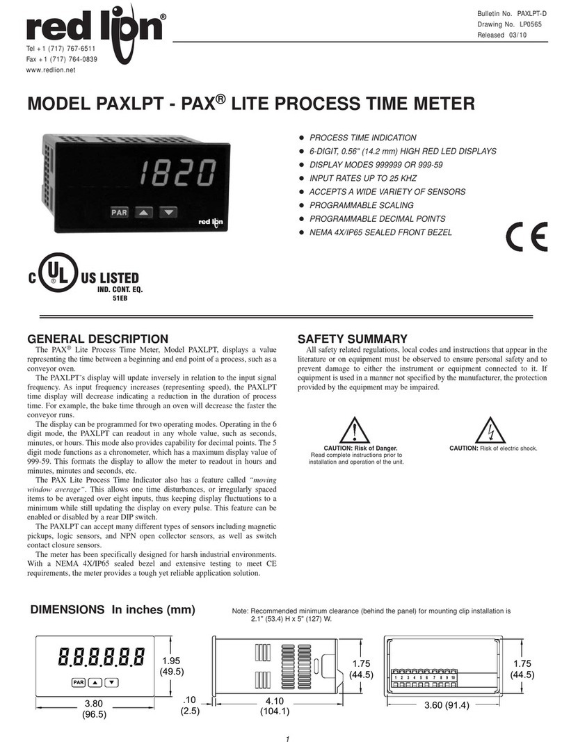
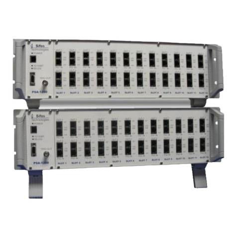
IMC CAEMAX DX User manual

CAEMAX Technologie GmbH
Bunzlauer Platz 1
Phone: 089 –61 30 49 - 0
D-80992 München
Fax: 089 –61 30 49 - 57
www.caemax.de
Manual
DXTelemetry System

DxTelemetry System
Manual Vers. 2.7
2/ 92
Table of Contents
1Introduction.................................................................................................................5
1.1 Abbreviations................................................................................................................................5
1.2 System Overview .........................................................................................................................5
1.3 Application....................................................................................................................................6
1.4 Packing.........................................................................................................................................7
2Technical Components ..............................................................................................8
2.1 Signal Conditioning Transmitter (Dx-SCT) ...................................................................................8
2.1.1 Voltage Inputs for Small Level Signal (Strain Gauges, Thermo couple, etc.)........................................9
2.1.2 Inputs for high-level signal (voltage measurement)...............................................................................9
2.1.3 Additional Channels for SCT Temperature and Supply Voltage .........................................................10
2.2 Terminal assignment SCT......................................................................................................... 11
2.2.1 Strain Gauge: Full Bridge....................................................................................................................11
2.2.2 Strain Gauge: Half Bridge...................................................................................................................12
2.2.3 Thermo couples Differential................................................................................................................13
2.2.4 Thermo couples Single Ended............................................................................................................13
2.2.5 High Level Voltage Differential............................................................................................................14
2.2.6 High Level Voltage Single Ended........................................................................................................14
2.3 Receiver Control Interface (RCI)............................................................................................... 15
2.3.1 Technical data ....................................................................................................................................15
2.3.2 Connections........................................................................................................................................16
3Quickstart..................................................................................................................18
3.1 Connect the DXRCI................................................................................................................... 18
3.2 Connect the DXSCT.................................................................................................................. 18
3.3 Turn the DXRCI on and off........................................................................................................ 18
3.4 Configure the DXwith a PC....................................................................................................... 18
3.5 Add a New SCT......................................................................................................................... 22
3.5.1 Create a New Device..........................................................................................................................22
3.5.2 Search for a SCT................................................................................................................................22
3.6 Channel Configuration............................................................................................................... 25
3.6.1 Generate a New Channel ...................................................................................................................25
3.6.2 Programming of Channels..................................................................................................................26
3.6.3 Define a Sample Rate.........................................................................................................................27
3.6.4 Configure Full Bridges / Half Bridges..................................................................................................30
3.6.5 Configure Thermocouples (differential or single ended) .....................................................................32
3.6.6 Configure High Level Voltage Inputs...................................................................................................33
3.7 Configure CAN Output .............................................................................................................. 34
3.7.1 Create/Delete CAN Message..............................................................................................................34
3.7.2 Edit/Save CAN Preferences................................................................................................................35
3.8 Configure Analog Output........................................................................................................... 37
3.9 Save and Export Settings.......................................................................................................... 38
3.9.1 Save Configuration (create .dxp File)..................................................................................................38
3.9.2 Load Configuration..............................................................................................................................38
3.9.3 Download .DXP File............................................................................................................................39
3.9.4 Automatically load Configuration File when booting............................................................................39
3.10 Start Measurement.................................................................................................................. 39
3.10.1 Measurement Mode and Configuration Mode...................................................................................39

DxTelemetry System
Manual Vers. 2.7
3/ 92
3.10.2 Configure Online Display..................................................................................................................40
3.10.3 Start and Stop Measurement............................................................................................................41
3.10.4 Start Measurement Automatically (Auto Measure Start)...................................................................42
4DXConfiguration Menu.............................................................................................43
4.1 Menu tree .................................................................................................................................. 43
4.2 Settings...................................................................................................................................... 45
4.2.1 Menu: Device Base RCI.................................................................................................................45
4.2.2 Menu: Device Device1 ...................................................................................................................46
4.2.3 Menu: Device New Device .............................................................................................................47
4.2.4 Menu: Channels Modes..................................................................................................................48
4.2.5 Menu: Channels Channel x............................................................................................................49
4.2.6 Menu: Outputs Output x .................................................................................................................50
4.2.7 Menu: CAN-Setup General.............................................................................................................51
4.2.8 Menu: CAN Setup Rem. Ctrl ..........................................................................................................52
4.2.9 Menu: CAN-Setup Message x........................................................................................................53
4.2.10 Menu: CAN-Setup New Msg. .......................................................................................................53
4.2.11 Menu: Ethernet .................................................................................................................................54
4.2.12 Menu: Measure Display x.............................................................................................................54
4.2.13 Menu: Measure Start....................................................................................................................55
4.2.14 Menu: Options ..................................................................................................................................56
4.2.15 Menu: Load/Save..............................................................................................................................57
5Energy Supply of SCTs............................................................................................58
5.1 Power Consumption and Supply Voltage.................................................................................. 58
5.2 Battery Supply........................................................................................................................... 59
5.3 Integrated Rechargeable Batteries ........................................................................................... 59
5.4 Ring Stator ................................................................................................................................ 59
5.4.1 Overview.............................................................................................................................................59
5.4.2 Technical Data....................................................................................................................................60
5.4.3 Installation and Placing into Operation................................................................................................60
5.5 Stator Head ............................................................................................................................... 64
5.5.1 Technical Data....................................................................................................................................64
5.5.2 Installation and Placing into Operation................................................................................................64
6Installation.................................................................................................................66
6.1 General Information................................................................................................................... 66
6.2 Safety Instructions..................................................................................................................... 66
6.3 Installation of the RCI................................................................................................................ 66
6.4 Installation of the SCT on a Rotating Device ............................................................................ 67
6.5 Installation of Secondary Coil for Inductive Power Supply........................................................ 68
6.5.1 Overall View........................................................................................................................................68
6.5.2 Step by Step Instructions....................................................................................................................69
7Accessories ..............................................................................................................72
7.1 Casings for DXTransmitter Units .............................................................................................. 72
7.1.1 SCT casing with Breakout Cable ........................................................................................................72
7.2 DXAntennas.............................................................................................................................. 73
7.2.1 Planar Antenna...................................................................................................................................73
7.2.2 Side Mirror Antenna............................................................................................................................74
7.3DXSatellites............................................................................................................................... 74

DxTelemetry System
Manual Vers. 2.7
4/ 92
8DXCustom Systems..................................................................................................75
8.1 RPM measurement option......................................................................................................... 75
8.1.1 System Overview................................................................................................................................75
8.1.2 Terminal Assignment of modified RCI.................................................................................................75
8.1.3 Incremental Angle Sensor...................................................................................................................76
8.1.4 Operating Instructions.........................................................................................................................77
8.1.5 Instructions for Commissioning and Maintenance ..............................................................................77
8.2 Settings...................................................................................................................................... 78
8.2.1 Menu: Channels → Local/RCI → Selection ........................................................................................78
8.2.2 Menu: Channels → Local/RCI → DX_Angle.......................................................................................79
8.2.3 Menu: Channels → Local/RCI → Rot. Speed .....................................................................................80
8.2.4 Menu: Channels → Local/RCI → Rot.Power ......................................................................................81
9Maintenance and Storage ........................................................................................82
9.1Cleaning and Maintenance ....................................................................................................... 82
9.2 Sensor Input Calibration............................................................................................................ 82
9.3 Storage...................................................................................................................................... 82
9.4 Customer Cable Modification.................................................................................................... 82
10 Questions & Answers...............................................................................................83
10.1 Inductive Power Supply: Troubleshooting............................................................................... 83
10.2 Integration of SCTs ................................................................................................................. 86
10.3 Changing the transmission frequency of SCT and RCI .......................................................... 86
10.4 Unstable signal, when connecting more than one SCT.......................................................... 87
10.5 DXRCI Firmware Update ........................................................................................................ 88
10.5.1 Checking firmware status..................................................................................................................88
10.5.2 Download new firmware....................................................................................................................88
10.5.3 Installing new firmware .....................................................................................................................88
11 EG Declaration of Conformity (after EN ISO/IEC 17050-1:2010)............................90
12 Formulas ...................................................................................................................91
12.1 Sensitivity of torsion measuring points.................................................................................... 91
12.1.1 Solid shaft sensitivity calculation.......................................................................................................91
12.1.2 Hollow shaft sensitivity calculation....................................................................................................91
12.1.3 k-factor sensitivity calculation ...........................................................................................................91
Due to the continuous developement of the product, CAEMAX Technologie GmbH reserves the right to modify it
and thus diverge from the description and technical points if it does not decrease its value.

DxTelemetry System
Manual Vers. 2.7
5/ 92
1 Introduction
We compliment you on the purchase of your new digital multi-channel telemetry system Dx.
The Dxis a state-of-the-art telemetry system for measurement technology.
We recommend you to acquaint yourself with the basics of the system before installing it or
putting it into operation.
1.1 Abbreviations
RCI
=
Receiver Control Interface
SCT
=
Signal Conditioning Transmitter
RSU
=
Receiver Satellite Unit
SD-Card
=
Memory Card
1.2 System Overview
The DXtelemetry system consists of one receiver unit (RCI) and up to four multi-channel
transmitters (SCTs). Up to 6 data channels per transmitter can be recorded. Measurement
data are digitalized at the transmitter and serially radio-transmitted to the receiver. A 200 Hz
sync signal of the RCI ensures synchrony of transmitters.
Data rate of radio channel is –depending on configuration –up to 100kbit/s.
Radio signals are received in diversity mode. Measurement values are displayed as analog
signals and CAN messages.
Energy supply of transmitters is very flexible: The SCTs can either be supplied inductively
(by stator head or ring stator), by commercial 9V batteries or by rechargeable batteries.

DxTelemetry System
Manual Vers. 2.7
6/ 92
Figure 1: System Overview
1.3 Application
The telemetry system Dxcan be used to receive, transfer and process electronically
measured variables. No liability will be accepted by the manufacturer when the system is not
used as intended.
The system is designed for the signal processing of strain gauges, thermo couples (-
200+1000°C) and analog voltage inputs (0...22V) (e.g. suitable for pressure sensors,
displacement transducers and accelerometers).

DxTelemetry System
Manual Vers. 2.7
7/ 92
1.4 Packing
The complete system will be delivered in one case.
Contents:
1. Receiver Control Interface (RCI)
2. Signal Conditioning Transmitter (SCT)
3. Ethernet cable
4. Rod antennas
5. Power supply
6. Manual
7. Optional: planar antennas
8. Optional: ring stator
9. Optional: assembly material for rotor application
Figure 2: Case Contents

DxTelemetry System
Manual Vers. 2.7
8/ 92
2 Technical Components
2.1 Signal Conditioning Transmitter (Dx-SCT)
Figure 3: Rotor Electronics (SCT)
RF- transmitter:
Freely programmable channel in the 868 MHz ISM band
(optionally 2.4GHz)
Transmission power:
Max. + 10dBm, will be adjusted as required and according
to the national restrictions (LBT procedures included)
Data transfer:
Package transfer with error detection
Power supply:
Contactless power supply by an inductive head with stator
winding or DC power supply 7.5V –39V
Temperature range:
-40°C … +85°C
Dimensions:
Approx. 45mm x 25mm x 10mm
Weight:
<14g

DxTelemetry System
Manual Vers. 2.7
9/ 92
2.1.1 Voltage Inputs for Small Level Signal (Strain Gauges, Thermo couple, etc.)
Either two differential voltage inputs to connect up to two full bridges or thermocouples, or to
connect four half-bridge inputs with internal half-bridge completion.
Input ranges:
± 2mV to ± 2V individually adjustable via RCT
(no external resistors or jumpers required)
Resolution:
16 bit
Accuracy:
±0.01% - ±0.025%
Sampling rate:
max. 4.6 kHz sampling rate (excluding additional channels)
Anti-aliasing filter:
6-pole Butterworth with cutoff frequency at 1/5 of the sampling rate
Bridge excitation:
+ 4.096 V (max. 40mA short-circuit proof)
Bridge balance:
> double measurement range, can be adjusted via RCT
Shunt test:
330 kΩ resistor, remote-controlled (as test signal to verify bridge
resistance or for detection of broken thermocouples)
2.1.2 Inputs for high-level signal (voltage measurement)
One differential input and one single-ended input
Input range:
± 0.2V to ± 22.5V individually adjustable via RCT
Resolution:
16 bit
Accuracy:
±0.01%
Sampling rate:
max. 4.6 kHz sampling rate (excluding additional channels)
Anti-aliasing filter:
6-pole Butterworth with cutoff frequency at 1/5 of the sampling rate

DxTelemetry System
Manual Vers. 2.7
10 / 92
2.1.3 Additional Channels for SCT Temperature and Supply Voltage
The extra channel of the SCT for temperature is also used as a reference for thermo couple
sensors.
Measurement range:
-30°C –+100°C
Resolution:
12 bit
Sampling rate:
25 Hz
The internal measurement of supply voltage can be used to monitor the battery voltage or to
check the quality of inductive power supply.
Measurement range:
- 41.5 V –+ 41.5 V
Resolution:
12 bit
Sampling rate:
25 Hz

DxTelemetry System
Manual Vers. 2.7
11 / 92
2.2 Terminal assignment SCT
21 3 4 5 6 87 9 10 11 12 13 14
Dx
pad
label
function
pad
label
function
1
IP1
Inductive-Power 1
8
I3
Ch2 Bridge Input +
2
DC+
DC-Power Plus
9
I2
Ch1 Bridge Input -
3
IP2
Inductive-Power 2
10
I1
Ch1 Bridge Input +
4
DC-
DC-Power Ground
11
I6
Ch 4 High Level SE+
5
EX-
Excitation -
12
GND
Analog-Ground
6
EX+
Excitation +
13
I5-
Ch3 High Level -
7
I4
Ch2 Bridge Input -
14
I5+
Ch3 High Level +
Caution: EX- and GND must not be connected (short circuit)
2.2.1 Strain Gauge: Full Bridge
Channel 1
Pad 5
Pad 6
Pad 10 Pad 9
R+ R
R- R
R+ R R- R
Channel 3
Pad 5
Pad 6
Pad 8 Pad 7
R+ R
R- R
R+ R R- R

DxTelemetry System
Manual Vers. 2.7
12 / 92
2.2.2 Strain Gauge: Half Bridge
Channel 1
Pad5
Pad6
Pad10
second path is added
in the DX
R
R+ R
Channel 2
Pad5
Pad6
Pad9
second path is added
in the DX
R
R+ R
Channel 3
Pad5
Pad6
Pad8
second path is added
in the DX
R
R+ R
Channel 4
Pad5
Pad6
Pad7
second path is added
in the DX
R
R+ R

DxTelemetry System
Manual Vers. 2.7
13 / 92
2.2.3 Thermo couples Differential
Channel 1
Pad 10
Pad 9
Thermo element
+
-
Channel 2
Pad 8
Pad 7
Thermo element
+
-
2.2.4 Thermo couples Single Ended
Channel 1
Pad 10
Pad 12
Thermo element
+
-
Channel 2
Pad 9
Pad 12
Thermo element
+
-
Channel 3
Pad 8
Pad 12
Thermo element
+
-
Channel 4
Pad 7
Pad 12
Thermo element
+
-

DxTelemetry System
Manual Vers. 2.7
14 / 92
2.2.5 High Level Voltage Differential
Channel 5
Pad 13
Pad 14
Pad 5 VVoltage signal
+
-
2.2.6 High Level Voltage Single Ended
Channel 6
Pad 12
Pad 11
Pad 5 VVoltage signal
+
-

DxTelemetry System
Manual Vers. 2.7
15 / 92
2.3 Receiver Control Interface (RCI)
Figure 4: RCI front
2.3.1 Technical data
Display:
2,83 inches IPS-display (In-Plane Switching)
Resolution:
320 x 240 px
Contrast:
10000:1 (TFT max. 400:1)
Perspective:
±85° no preferred view angle (TFT approx. ±70°)
Input interface:
Rotary multi-selector with five keys
Analog outputs:
6 BNC jacks, freely assignable
Output range:
±10 V with fixed frequency lowpass filter
Resolution:
16 bit
Accuracy:
±0.01% full scale
High-frequency receiver:
Channel freely programmable in the 868 MHz ISM band
(optionally 2.4GHz)
Transceiver:
2 independent systems operated in diversity mode

DxTelemetry System
Manual Vers. 2.7
16 / 92
Synchronization:
synchronized sampling and adjusted transmission
frequencies of up to four Dx-SCT units, resulting in a
synchronous data stream
Voltage supply:
9 –36 volts DC
Input power
< 5W (without inductive energy supply of the transmitters)
Temperature range:
-20°C - +65°C
Dimensions:
approx. 170mm x 130mm x 53mm
Weight:
approx. 0.8kg
2.3.2 Connections
Figure 5: RCI back
SMA jack:
antenna plug
Banana jacks:
For DC power supply of RCI (9V-36V)
Please note: These connectors are not designed to supply
a ring stator or stator head!
Power jack:
External power supply connector
USB jacks:
USB 2.0 Full Speed/12 Mbit for Plug and Play-
configuration
Head/RSU:
D-SUB 15 receptacle to plug in an optional satellite receiver
CAN:
CAN 2.0b, standard and extended identifier, freely
programmable max. 1 Mbaud
connection according to ISO 11898, galvanic isolation
Ethernet:
10/100 Mbit network connection with web server for the
configuration
SD-Card (side):
Standard SD slot to save the configuration.
Optionally: self-sufficient data storage, currently up to 4 GB.
BNC jacks (front):
6 analog outputs, assignable as required

DxTelemetry System
Manual Vers. 2.7
17 / 92
2.3.2.1 Pin Assignment of D-Sub CAN Connector (9 pol)
Figure 6: pin assignment of D-Sub CAN connector
pin
CiA name
function
1
--
not used
2
CAN_L
CAN_L, dominant low
3
CAN_GND
GND
4
--
not used
5
--
not used
6
--
not used
7
CAN_H
CAN_H, dominant high
8
--
not used
9
--
not used

DxTelemetry System
Manual Vers. 2.7
18 / 92
3 Quickstart
3.1 Connect the DXRCI
Connect the DXRCI to a power source. Therefore, use the DC-Inputs (9-36V DC) or
connect the included power cable to the mains voltage.
To configure the DXvia PC, connect the PC and DXwith the included Ethernet cable.
For data transmission via CAN-Bus, connect a CAN cable (CAN1: CAN-Output;
CAN2: CAN-Input)
Please note: The DXhas no built-in CAN terminating resistor. In case the DXis
placed at the end point of a CAN bus chain, you have to place a 120 Ω termination
resistor between connector and CAN jack.
Plug BNC cables to the analog outputs of the RCI to tap measurement data. Analog
outputs are freely programmable to all data channels (for configuration, see section
3.8).
3.2 Connect the DXSCT
Connect the DXSCT to a power source. The SCT can either be supplied by
battery/rechargeable battery or inductively by a ring or fix stator. As soon as supplied with
power, the SCT is transmitting measurement data. Please refer to Section 2.2 for more
information on power input connection.
Note: To check whether voltage application to drive the SCT is sufficient, measure the strain
gauge supply voltage (see section 2.2). Its voltage level is 4.096 ± 0.1 V when the device is
sufficiently supplied.
3.3 Turn the DXRCI on and off
To turn the DXRCI on or off, press the button in the center of the scroll wheel for about 5
seconds.
3.4 Configure the DXwith a PC
With this function, configuration can be done conveniently with your PC instead of using the
scroll wheel.
To configure the Dxusing a Web browser, a local network connection between Dxand
measuring computer must be set up. Connect the Ethernet interface of the Dx to your
computer with an Ethernet cable.
Please note: Your computer must be assigned with an IP address (IPv4 protocol) from the
same network segment (i.e, the first three digits has to match with the DXIP address).
Factory setting of the DxIP-address is 192.168.000.212.
In this case, assign for example the IP address 192.168.000.100 to your computer.
Furthermore, deactivate your computer’s dynamic address assignment (DHCP).

DxTelemetry System
Manual Vers. 2.7
19 / 92
Figure 7: Network and Sharing Center
To do this with Windows 7, open the Network and Sharing Center and click on LAN-
Connection. In the LAN connection dialog, select Properties (Administrator privileges
required!).
Figure 8: LAN connection status
Select Internet protocol Version 4 (TCP/IPv4) and click on Properties.

DxTelemetry System
Manual Vers. 2.7
20 / 92
Figure 9: LAN connection properties
Now select Use the following IP address, type in the desired IP address and confirm with OK.
Figure 10: IP address
If you don’t succeed in connecting to the DX, please check your firewall settings. In this case,
you may also ask your system administrator.
Table of contents
Other IMC Measuring Instrument manuals
Popular Measuring Instrument manuals by other brands
Sontex
Sontex Supercal 531 Installation and manual
PLS
PLS HVR 505 operating manual

Jinsaixun electronics technology co., ltd
Jinsaixun electronics technology co., ltd SM-2008 Operator's manual

West Mountain Radio
West Mountain Radio CBA IV manual

Kusam-meco
Kusam-meco KM 1120 Operation manual
ECG
ECG CX-920A user manual
