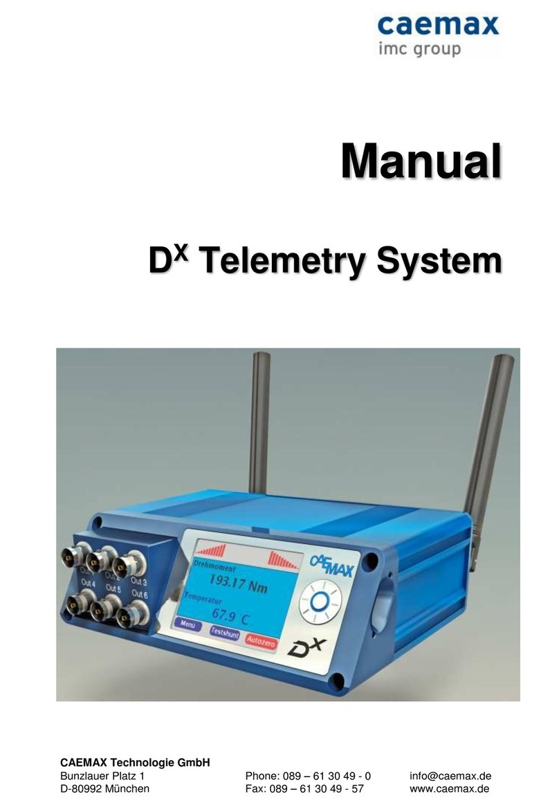
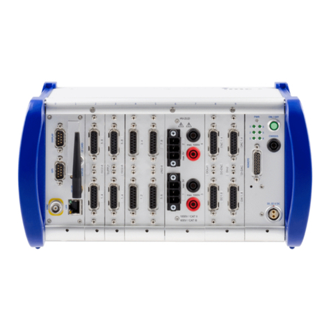
IMC CRONOSflex User manual

imc CRONOS
Getting Started Version 1.8 - 08.01.2014
© 2014 imc Meßsysteme GmbH
imc Meßsysteme GmbH • Voltastraße 5 • 13355 Berlin • Germany
flex

2Table Of Contents
© 2014 imc Meßsysteme GmbH
Table Of Contents
imc CRONOSflex
................................................................................................................................... 6
1.1 imc CRONOSflex Description of the system
......................................................................................................................................................... 6
1.1.1 Building Block Principle Maximizes Flexibility
......................................................................................................................................................... 6
1.1.2 System bus
......................................................................................................................................................... 6
1.1.3 Modular components "click" together
......................................................................................................................................................... 7
1.1.4 Distributed measurement system
.................................................................................................................................................. 7
1.1.4.1 System structure and components
.................................................................................................................................................. 7
1.1.4.2 Use with imc CRONOScompact
.................................................................................................................................................. 8
1.1.4.3 Deployment in 3rd party EtherCAT systems
................................................................................................................................... 10
1.2 Device supply
......................................................................................................................................................... 10
1.2.1 Networking and power supply
......................................................................................................................................................... 12
1.2.2 Main switch
.................................................................................................................................................. 12
1.2.2.1 Remote control of the main switch
.................................................................................................................................................. 12
1.2.2.2 REMOTE plug
......................................................................................................................................................... 12
1.2.3 PoE - Power over EtherCAT
......................................................................................................................................................... 13
1.2.4 Saving data in case of power outage
......................................................................................................................................................... 13
1.2.5 Stabilized device supply and UPS (Power Handle)
................................................................................................................................... 13
1.3 Isolation and grounding concept
......................................................................................................................................................... 13
1.3.1 Isolation
......................................................................................................................................................... 14
1.3.2 Grounding concept
.................................................................................................................................................. 14
1.3.2.1 Isolated power inputs avoids ground loops in distributed topologies
.................................................................................................................................................. 15
1.3.2.2 Forced grounding via the AC/DC adapter's safety ground
................................................................................................................................... 16
1.4 Power supply options
......................................................................................................................................................... 16
1.4.1 Overview of power supply options
......................................................................................................................................................... 17
1.4.2 Possible supply configurations
......................................................................................................................................................... 18
1.4.3 Directly stacked modules
......................................................................................................................................................... 19
1.4.4 Overall system consisting of multiple blocks
......................................................................................................................................................... 20
1.4.5 Supplemental device power supply (Power Handle)
......................................................................................................................................................... 21
1.4.6 Overview of available operation and remote control modes
......................................................................................................................................................... 22
1.4.7 Charging the internal battery of a Power-Handle having UPS-functionality
......................................................................................................................................................... 24
1.4.8 PoE (Power over EtherCAT) operation
......................................................................................................................................................... 25
1.4.9 Operation with multiple (varying) supply voltages
Getting started
................................................................................................................................... 26
2.1 Internal system-bus: Network cables
................................................................................................................................... 27
2.2 Overview of imc CRONOSflex Modules
................................................................................................................................... 27
2.3 Overview power consumption
................................................................................................................................... 28
2.4 imc CRONOSflex Module attachment mechanism
................................................................................................................................... 29
2.5 Installation - Software
......................................................................................................................................................... 29
2.5.1 System requirements
................................................................................................................................... 30
2.6 Connecting via LAN in four steps
......................................................................................................................................................... 30
2.6.1 Step 1: Determining the PC's IP-address
......................................................................................................................................................... 32
2.6.2 Step 2: Connecting the measurement device
......................................................................................................................................................... 32
2.6.3 Step 3: IP-configuration via imc DEVICES Interface Configuration
......................................................................................................................................................... 34
2.6.4 Step 4: Integrating a device into an experiment

3Table Of Contents
© 2014 imc Meßsysteme GmbH
................................................................................................................................... 37
2.7 Ethernet Interface
......................................................................................................................................................... 37
2.7.1 Software requirements Ethernet-Interface
......................................................................................................................................................... 37
2.7.2 Network connection (cabeling)
......................................................................................................................................................... 37
2.7.3 TCP/IP network protocol
......................................................................................................................................................... 37
2.7.4 Assign the IP address
................................................................................................................................... 37
2.8 Firmware-Update
......................................................................................................................................................... 40
2.8.1 Enable / Disable
Connection with connectors
................................................................................................................................... 41
3.1 Connecting DSUB-15 adapter plug
......................................................................................................................................................... 42
3.1.1 Overview of the modules and connectors
................................................................................................................................... 43
3.2 Metal connector
................................................................................................................................... 44
3.3 DSUB-15 Pin configuration
......................................................................................................................................................... 44
3.3.1 Standard and Universal connector
......................................................................................................................................................... 45
3.3.2 Special connector
......................................................................................................................................................... 46
3.3.3 TEDS connector
................................................................................................................................... 47
3.4 DSUB-9 plugs
......................................................................................................................................................... 47
3.4.1 Pin configuration of the field busses
.................................................................................................................................................. 47
3.4.1.1 CAN-Bus (DSUB-9)
.................................................................................................................................................. 47
3.4.1.2 J1587-Bus (DSUB-9 option)
.................................................................................................................................................. 47
3.4.1.3 LIN-Bus (DSUB-9 option)
.................................................................................................................................................. 48
3.4.1.4 FlexRay-Bus (DSUB-9 option)
.................................................................................................................................................. 48
3.4.1.5 MVB-Bus (DSUB-9)
.................................................................................................................................................. 49
3.4.1.6 ARINC-Bus (DSUB-15)
.................................................................................................................................................. 50
3.4.1.7 PROFIBUS (DSUB-9 option)
......................................................................................................................................................... 51
3.4.2 Pin configuration Display, Modem, GPS
.................................................................................................................................................. 51
3.4.2.1 Display
.................................................................................................................................................. 51
3.4.2.2 Modem (external)
.................................................................................................................................................. 51
3.4.2.3 GPS receiver
................................................................................................................................... 52
3.5 DSUB-26 Pin configuration (High Density)
................................................................................................................................... 52
3.6 REMOTE plug
................................................................................................................................... 53
3.7 Modules with LEMO plugs
Last Changes
................................................................................................................................... 54
4.1 Product improvement
................................................................................................................................... 54
4.2 Error remedies in version 1.8
................................................................................................................................... 54
4.3 Changes in version 1.7
................................................................................................................................... 54
4.4 Error remedies in version 1.6
................................................................................................................................... 55
4.5 Error remedies, what is new in this version 1.5
................................................................................................................................... 55
4.6 Error remedies in version 1.4
................................................................................................................................... 55
4.7 Error remedies in version 1.3
................................................................................................................................... 55
4.8 Changes in version 1.2
................................................................................................................................... 55
4.9 Error remedies in version 1.1
................................................................................................................................... 55
4.10 Error remedies in version 1.0
Attachment
4Table Of Contents
© 2014 imc Meßsysteme GmbH
................................................................................................................................... 56
5.1 Precautions for operation
................................................................................................................................... 57
5.2 imc Customer Support - Hotline
................................................................................................................................... 57
5.3 Guidelines
......................................................................................................................................................... 57
5.3.1 Certificates and Quality Management
......................................................................................................................................................... 57
5.3.2 imc Guarantee
......................................................................................................................................................... 57
5.3.3 ElektroG, RoHS, WEEE
......................................................................................................................................................... 58
5.3.4 Important notes
.................................................................................................................................................. 58
5.3.4.1 Remarks Concerning EMC
.................................................................................................................................................. 58
5.3.4.2 FCC-Note
.................................................................................................................................................. 58
5.3.4.3 Cables
.................................................................................................................................................. 58
5.3.4.4 Industrial Safety
................................................................................................................................... 59
5.4 Transporting and storage
......................................................................................................................................................... 59
5.4.1 After unpacking...
......................................................................................................................................................... 59
5.4.2 Transporting imc CRONOSflex
......................................................................................................................................................... 60
5.4.3 Cleaning
......................................................................................................................................................... 60
5.4.4 Safety .................................................................................................................................................. 60
5.4.4.1 Responsibility of the user
.................................................................................................................................................. 60
5.4.4.2 Operating personnel
.................................................................................................................................................. 61
5.4.4.3 Special dangers
Index 62

imc CRONOSflex Getting Started Version 1.8 - 08.01.2014
5
imc CRONOSflex
flexible, expandable and
decentralized measurement systems
To look for WHAT?
Where?
Description
Before starting
building block principle
networking and power supply
main switch
saving data in case of power outage
isolation and grounding concept
power supply options
supplemental device power supply
Getting started
"Click"-Mechanism
attachment mechanism
overview of the available modules
installation of the software
firmware update
Terminal connection
DSUB-15
DSUB-26
LEMO connector
DSUB-9
Service
Hotline
imc Guarantee
www.imc-berlin.com -> imc CRONOSflex
The imc CRONOSflex is a modular system providing an unprecedented
degree of flexibility in configuring an integrated measurement and control
solution. The system does not require any mounting rack or mainframe:
both the base unit and the measurement modules (amplifiers or signal
conditioners) are self contained, but are easily stacked together by means
of a robust “click"-mechanism. To complete the portable system or even
to expand the input supply options of the system handles can be stacked
to the modules by means of the mechanism.
Alternatively, the modules can be connected through standard commercial network cables, allowing a
spatially distributed system topology with up to 100 m between individual modules.
With signal bandwidths of up to 48 kHz per channel, and an aggregate sampling rate of up to
2 MSample/s, imc CRONOSflex covers the frequency range of virtually all physical, mechanical, and
electromechanical signals. Amplifiers with integrated signal conditioning are available for all common
sensor types.
6
10
12
13
13
16
20
28
27
29
37
41
52
53
47
57
57
6

imc CRONOSflex Getting Started Version 1.8 - 08.01.2014
imc CRONOSflex6
1.1 imc CRONOSflex Description of the system
1.1.1 Building Block Principle Maximizes Flexibility
The inherently modular construction of imc CRONOSflex eliminates the constraints of a predefined
system size or configuration , found in usual data acquisition systems. Integrated modules free the
user to design – and redesign – their system as required: small and compact one day; a large number of
channels, of different sensor types with tailored signal conditioning the next. Today a centralized bench
top system; tomorrow a decentralized system with satellite modules each assigned to a remote
measurement site. The flexibility of imc CRONOSflex allows the reuse of system components to build the
optimal solution in a matter of seconds; the system’s scalable and expandable architecture eliminates
the need for exact planning when purchasing equipment for a specific application. Based on EtherCAT,
the system bus to connect the central base unit with measurement modules, it is possible to both
connect the measurement modules directly to a central unit, and/or to set up a spatially distributed
system by means of standard Ethernet network cables (RJ45, CAT5). The resulting measurement system
can be managed from a PC (also connected via an Ethernet LAN or WLAN) which serves as the
configuration tool and repository for measured data.
However, the system can also work autonomously without a control PC: either starting immediately
upon being powered, or automatically at a specified time according to a pre-set autostart configuration.
In either case, the recorded data may be saved to the device’s storage (hard drive, flash card or USB
media), or to a network drive. Data can be retrieved from a remote device directly (removable storage
media), or via the network if there is a (temporary) outside connection.
1.1.2 System bus
The selection of EtherCAT as the system bus provides the user with the advantage of being able to set up
a distributed measurement system with standard CAT 5 network cables, including those in an existing
Ethernet infrastructure. EtherCAT’s software protocol is an established industry standard which supports
deterministic transfers and synchronization mechanisms, guaranteeing precisely synchronized
measurements throughout the network. The fact that the measurement module networking is
compatible with the EtherCAT standard is not generally important in itself to most users, since this only
affects the system bus administered internally between the base unit and the measurement modules,
and not the connection with the control PC. However, being an industrial standard, the choice of
EtherCAT opens up a whole new dimension for large automation customers and 3rd party system
integrators: imc CRONOSflex Modules can be operated without the imc CRONOSflex Base Unit when
used as components within an EtherCAT-based automation system . There they function as EtherCAT
Slaves with full CANopen over EtherCAT (CoE) support.
1.1.3 Modular components "click" together
The individual modules are constructed to form a tight mechanical connection "with a click", while being
electrically connected to the imc CRONOSflex data bus and, if desired, power. When added or removed,
hardware modules are also automatically included/excluded by the imc STUDIO software. An optional
powered handle unit can be attached to the stack in the same manner as imc CRONOSflex Modules,
optionally containing a stabilized 50 V system power supply unit with buffered uninterruptible power
supply (UPS). When “clicking together (connecting the components)” modules in this way, you create a
portable, centralized measurement system which can subsequently be customized both in terms of the
module types and quantity.
19
6
8

imc CRONOSflex Getting Started Version 1.8 - 08.01.2014
imc CRONOSflex Description of the system 7
1.1.4 Distributed measurement system
For even more flexibility, the EtherCAT based imc CRONOSflex system can be physically distributed using
standard cables (RJ45, CAT5). Additional measurement modules can be connected, individually and as
local blocks of modules which are locally clicked together, but remote from the base unit. The
combination of these two connection techniques, centralized “clicked” stacks and distributed cable
connected modules and substacks, allows any imaginable topology of measurement locations to be
joined together into a logically integrated, centrally controlled, data acquisition and control system.
The spatial distribution of such a measurement system can extend to distances of 100 m between any
two components. This makes it possible to place measurement modules in close proximity to local
measurement sites and sensors, in many cases drastically reducing the amount of wiring required.
Consider as well that long signal cables, especially carrying weak analog measurement signals, are
generally much more sensitive to electrical interference problems than the error-tolerant network
connections used by imc CRONOSflex. Consequently, a distributed system topology can benefit from a
more flexible and cost effective setup, with improved signal quality.
1.1.4.1 System structure and components
A complete system always consists of a central imc CRONOSflex Base Unit and a flexible amount of imc
CRONOSflex Modules. The imc CRONOSflex Base Unit is available as a variety of models. With either one
or two field-bus interfaces (each with two nodes), as well as an optional Multi-IO extension, which
provides digital inputs and outputs plus incremental counter measurement channels and analog outputs.
imc CRONOSflex as a decentralized, distributed measurement system
1.1.4.2 Use with imc CRONOScompact
One additional use for the flex-series’ signal conditioning modules is in conjunction with an
imc CRONOScompact system: in contrast to CRONOSflex system, CRONOScompact is a “rack”-based
series of devices, which can accommodate several conditioners as plug-in modules in a device frame.
These “CRC-plug-in modules” do not have either their own housing nor their own power supply, and are
not spatially distributed. The imc CRONOScompact system can be equipped with an EtherCAT-Master
interface via which the system can be expanded with additional external imc CRONOSflex Modules, to
achieve both an increased system throughput and a distributed system topology.
As with the CRONOSflex system, in this environment, too, the “external” signal conditioners are fully
supported by and integrated into operating software (imc STUDIO / imc DEVICES). There are no
appreciable differences between operation and administration of “internal” CRC plug-in modules and

imc CRONOSflex Getting Started Version 1.8 - 08.01.2014
imc CRONOSflex8
“external”, distributed imc CRONOSflex Modules. EtherCAT as the system bus is only internally relevant,
and do not require the user to be concerned with the mechanisms and protocols used.
Expanding an imc CRONOScompact system with decentralized imc CRONOSflex Modules
1.1.4.3 Deployment in 3rd party EtherCAT systems
The imc CRONOSflex Modules can additionally be deployed as subscribers in any kind of EtherCAT bus
system. In such a system, which is not controlled by the imc CRONOSflex Base Unit, but rather by a Bus
Master (EtherCAT Master) from a different supplier, the modules are treated as slave subscribers. All
modules can be controlled and configured via CoE (CANopen over EtherCAT) and FoE (File Access over
EtherCAT), ensuring that they are universally deployable. Due to the ability to save multiple
configurations, the efforts in setting up operations is dramatically reduced.
One very easy alternative way to set signal conditioner parameters without any need for programming is
provided by the ability to use the operating software imc STUDIO / imc DEVICES to first make the settings
and then to save them as an “autostart”-configuration. Subsequently, the modules can be used
independently in 3rd party systems working in a “permanent” configuration and no longer requiring
parameterization.
imc CRONOSflex Module integrated into an EtherCAT-based automation system

imc CRONOSflex Getting Started Version 1.8 - 08.01.2014
imc CRONOSflex Description of the system 9
Even an entire CRONOSflex system, consisting of the base unit and multiple signal conditioners can be
integrated into the 3rd party system having a “3rd-party” EtherCAT bus-master: For this purpose, the
CRONOSflex Base Unit can be equipped with an EtherCAT device interface, making the entire device
available as a data source in the sense of an EtherCAT slave device. The respective interface module
(ECAT-IF) is available as one of multiple optional fieldbus expansions of the CRONOSflex Base Unit. To
parameterize this sub-system in turn, the imc STUDIO operating software can be used.
imc CRONOSflex as complete slave subsystem within an EtherCAT-based 3rd party system

imc CRONOSflex Getting Started Version 1.8 - 08.01.2014
imc CRONOSflex10
1.2 Device supply
1.2.1 Networking and power supply
All of the system’s individual building blocks, both the imc CRONOSflex Base Unit and also each individual
imc CRONOSflex measurement module, have their own LEMO plug for an ultra-wide 10 to 50 V range of
DC power input; additionally, each have two RJ45 network jacks (IN/OUT) for connecting the EtherCAT
system bus. Both lines have robust connection terminals which provide both mechanical attachment to
modules (locking snap) and electrical connection without any additional cables. By this means, multiple
directly attached modules can be jointly powered by a single DC source which is always connected at the
“far left” or “first” module . If multiple power sources are accidentally connected to the same block of
modules, then a latch circuit ensures that only the first module on the left receives the power.
With the introduction of the 48 VDC power adapter for the imc CRONOSflex system (Base Unit and the
Input Modules), the power supply plug on the device has been changed so that the 48 VDC power
adapter can only be used with imc CRONOSflex systems and not with other imc measurement devices
with an input supply voltage of 10..32 VDC. You can identify the 48 VDC power adapter at the blue
protective sleeve at the LEMO.1B plug (LEMO.PHG.1B.302). The 15 VDC or the 24 VDC power adapters
are equipped with a black protective sleeve at the LEMO.1B plug and can also be used with imc
CRONOSflex systems. The use of those power adapters with imc CRONOSflex is not recommended.
The imc CRONOSflex system have an input supply voltage range of 10 .. 50 VDC.
Former plugs (female):
input power supply plug LEMO.1B (female)
for a connection with 24 VDC power adapter
(1 guide notch, LEMO.EGG.1B.302)
New plugs (female):
CRFX Base Unit (CRFX-400, CRFX-2000) as of revision 5
and CRFX Module as of revision 7, see type label
input power supply plug LEMO.1B (female)
for a connection with 48 VDC power adapter
(2 guide notches, LEMO.EGE.1B.302)
plug-type (female):
LEMO.EGG.1B
LEMO.EGE.1B
1 coding notch
up to 8/2011
2 coding notches
as of 9/2011
connector-type (male):
power adapter:
LEMO.FGG.1B
1 coding key
15 V, 24 V
fit
fit
LEMO.FGE.1B
2 coding keys
48 V
fits only with
ACC/FGG-ADAP-PHE
fit
16

imc CRONOSflex Getting Started Version 1.8 - 08.01.2014
Device supply 11
If the imc CRONOSflex Base Unit runs with 48 VDC power supply rather than the 24 VDC power supply, it
is possible to operate a larger number of modules or a module with more power consumption directly
with one power adapter. The power consumption of the modules can be as high as 148.8 W with a 48
VDC power supply. If you want to benefit of the PoE (Power over Ethernet) function a minimum
voltage of 42 VDC is necessary.
For all previously delivered imc CRONOSflex systems with the LEMO.EGG.1B power supply plug (with one
guide notch), to be powered in future with 48 VDC, use the adapter cable "CRFX adapter cable for the
supply LEMO.1B (article number: 1350151, order code: ACC/FGG-ADAP-PHE)" and the 48 VDC power
adapter.
Note
This adapter cable may only be used with imc CRONOSflex. For devices with the
10..32 VDC input voltage range (imc C-SERIES, imc SPARTAN, …), use of this adapter cable and
the 48 VDC power unit can damage or destroy the devices.
power adapter 48 V up to 150 W
(with blue protective sleeve at the plug)
article number: 1350148
All imc CRONOSflex Base Units and Input Modules having the changed power supply plug can be
continued to be powered with the 24 VDC power adapter (without adapter cable).
24

imc CRONOSflex Getting Started Version 1.8 - 08.01.2014
imc CRONOSflex12
1.2.2 Main switch
The imc CRONOSflex Base Unit has a central main switch by which the complete block of directly clicked
(stacked) modules is activated/deactivated. Independently powered, spatially distributed modules and
subsystems (blocks) are activated/deactivated directly via their power supply connections.
1.2.2.1 Remote control of the main switch
As an alternative to the manual main switch on the device's front panel, a remote-controllable electric
contact can be used to switch the device on and off. The connector designated "REMOTE" provides this
contact: connecting the signals "SWITCH" and "ON" switches the device on, connecting "SWITCH" to
"OFF" switches the device off. Any switch or relay contact used for this purpose must be able to bear a
current of approx. 50 mA at 10 max. The reference voltage for these signals is the primary voltage
supply.
The signal "SWITCH1" serves to run the device with the switch permanently bridged: when "ON" and
"SWITCH1" are connected, the device starts as soon as an external supply voltage is provided.
If this supply is interrupted, an internal buffer keeps the base unit activated for the appropriate buffer
duration in order to close the measurement and files, and then the device deactivates itself. This type of
operation is specially designed for use in a vehicle, permanently couples to the ignition and not requiring
manual control.
LEMO.1B.306 plug
LEMO
Signal
LEMO
Signal
1
ON / OFF
4
SWITCH
2
SWITCH1
5
n.c.
3
ON / OFF
6
n.c.
1.2.2.2 REMOTE plug
Possible configurations:
Function
Jumper between
Switch on and off „normal“
SWITCH and ON / OFF
Switch on when connected to main supply only jumpered main switch
SWITCH1 and ON / OFF
1.2.3 PoE - Power over EtherCAT
imc CRONOSflex Modules are compatible with “Power-over-EtherCAT” (PoE), meaning they can receive
power completely from the EtherCAT connection cable and consequently no longer need their own
power supply line. This is especially attractive for decentralized satellite modules positioned somewhere
remote and inaccessible, and having no other outside line than the CAT5 cable. Thus, centrally remote-
controlled activation/deactivation of these satellites is achievable by means of PoE.
The PoE specifications determine the maximum power deliverable by the network cable. It may be
sufficient for multiple modules, depending on their types. PoE is supported for single modules each
connected by patch cables, but not for substacks of modules.
20

imc CRONOSflex Getting Started Version 1.8 - 08.01.2014
Device supply 13
1.2.4 Saving data in case of power outage
In case of an outage or interruption of the system’s DC power supply, an
internal buffer battery in the base unit ensures that any running
measurement is ended in a controlled manner, that all measured data are
safely transferred to the internal data storage and that the associated files
are correctly closed. This procedure can take up to several seconds.
Subsequently, the system shuts down automatically.
The standard-equipped system’s internal supply buffering extends to the
base unit, not the imc CRONOSflex Modules which are either directly
stacked or connected by cable, and is provided for the purpose of
preserving the data integrity under any conceivable operating
circumstances.
CRFX-400 with
CAN-Bus Interface
Additional buffering for the entire system, including the imc CRONOSflex Modules, so as to ensure
uninterrupted measurement operation even during phases of power failure, is also possible in
conjunction with the optional UPS supply module which comes with the carrying handle. This makes
mobile battery operation possible, or even bridge over power during vehicle starting processes. With
UPS operation of this type, it is possible to set a so-called “buffer time”: this time period specifies after
how long a continuing power outage is no longer to be backed up, and thus when closure of the
measurement and automatic deactivation are to be initiated.
1.2.5 Stabilized device supply and UPS (Power Handle)
Comprehensive systems with correspondingly high performance
requirements can, in conjunction with low supply voltage and thus a high
resulting current (e.g. 12 V in a vehicle), exceed the amperage capacity of
the module terminal connections (max. 3.1 A). For this reason the
possibility is provided to equip the left carrying handle with an optional
supply unit, which generates a constant high system supply voltage of
50 V at max. 100 W from the 10 V to 50 V wide range supply voltage.
Power Handle
This not only makes it possible to reliably supply very large systems, but also to use the measurement
modules’ PoE capabilities across the entire wide voltage supply range: according to PoE specs, for PoE
functionality a minimum supply voltage of 42 V on the network line is required. This is provided by the
supply unit in the handle for the entire 10 V to 50 V range.
Reference
The optional handle can additionally be equipped with a UPS function to ensure the device’s
operation even during a power outage. UPS units are available with a choice of either lead or Li-ion
batteries.
1.3 Isolation and grounding concept
1.3.1 Isolation
The imc CRONOSflex Modules’ supply inputs are each isolated from the frame (CHASSIS) and
measurement electronics. This ensures in particular that in spatially distributed systems, where no
common CHASSIS or ground voltage for all subsystems can be assumed, neither uncontrolled ground
loops nor compensation currents occur. Neither the base unit’s supply input, nor the voltage it supplies
to the measurement modules, is isolated. In a distributed system, therefore, the base-system’s housing
(CHASSIS), and the directly connected amplifiers, as well as their supply voltage level are to be seen as
the central reference voltage (neutral point), to which the distributed satellites and their respective
20

imc CRONOSflex Getting Started Version 1.8 - 08.01.2014
imc CRONOSflex14
frames and supply voltages may each have a voltage differential. For the purpose of controlled
grounding, each of the imc CRONOSflex Modules has a dedicated grounding contact on the lower part of
its front panel.
Since the various housing frames and their reference grounds have a connection to the network cables
via the shielding, it may be necessary to use network cables whose shielding has contact on only one
side. In especially demanding applications, such as installation on board rail vehicles, where high static as
well as dynamic ground differentials can exist across the various wagons, it is also possible to use fiber
optic network converters for a pure optic EtherCAT system bus connection. Appropriate mechanically
integrated converter modules for CRONOSflex are in preparation.
Concerning the isolation of imc CRONOSflex Measurement Modules’ electronics from their respective
frames, there are different options: modules both with isolated measurement inputs (e.g. ISO2-8) and
without isolated measurement inputs (e.g. UNI2-8) are available.
1.3.2 Grounding concept
1.3.2.1 Isolated power inputs avoids ground loops in distributed topologies
With stationary installations and the use of (already isolated) AC/DC adapters, any system ground
differentials between the device and the central or local power supplies may not be relevant. The big
issue in such a case, in contrast to mobile, in-vehicle applications, is from where to obtain a reliable
ground voltage. Since it is convenient to use the AC power supply’s protection ground line as the ground
voltage, the LEMO-terminated AC/DC adapters for imc CRONOS measurement devices are designed so
that the protection ground line is connected all the way through to the LEMO connector’s housing, thus
securing the device’s voltage level to protection ground. Additionally, in the AC/DC-adapter’s LEMO-
terminal (not the device’s LEMO-socket!), the reference ground of the power adapter is connected with
the housing’s (CHASSIS) protection ground: Since the AC/DC power adapter is already isolating, as is the
power input, this supply voltage’s reference would not initially be defined and can be set arbitrarily. In
particular for reasons of suppressing HF (high-frequency) interference signals stemming from the AC/DC
switching power adapter, direct grounding is normally advisable.

imc CRONOSflex Getting Started Version 1.8 - 08.01.2014
Isolation and grounding concept 15
1.3.2.2 Forced grounding via the AC/DC adapter's safety ground

imc CRONOSflex Getting Started Version 1.8 - 08.01.2014
imc CRONOSflex16
1.4 Power supply options
1.4.1 Overview of power supply options
(1)
via the imc CRONOSflex Base Unit
for modules directly attached to the Base Unit
multiple measurement modules operable at one base unit
activation/deactivation via central main switch on the base unit
in particular with low supply voltage and (12 V) and high resulting current, the connectors’
maximum current carrying capacity (3.1 A) must be taken into account, which can limit the
maximum size of a module block powered in common: max. 37.2 W (12 V)
an optional supply module in the leftmost carrying handle ensures a common power supply
for any size of blocks by providing a constant voltage of 50 V at max. 100 W for any input
voltage between 10 to 50 V
(2)
individual power supply
for modules which are connected by CAT5 network cables across a wide area
10 V to 50 V DC via LEMO.1B socket
activation/deactivation by connection of the power supply
(3)
joint supply of a module substack
a block can consist of: a Base Unit with signal conditioners, a block of purely signal
conditioners and/or a block with a power supply module (the Power Handle)
The power supply for stacked modules must always come via the LEMO-socket through the
outer left module (looking at the conditioner terminals, the display and model plaque are on
the left), the LEMO terminals of the other modules are then disconnected. A module’s LEMO-
socket is always deactivated whenever its neighbor to the left is directly connected via a
module’s plug-in connector. For the supply of the leftmost module within a block, the actual
voltage is the higher of either the voltage applied to the LEMO or the voltage passing through
the previous block’s patch cable (PoE-voltage).
activation/deactivation by connection of the power supply
The maximum block-size depends on how high the supply voltage is (see above).

imc CRONOSflex Getting Started Version 1.8 - 08.01.2014
Power supply options 17
(4)
via the Ethernet network cable
according PoE (Power over EtherCAT)
PoE – supply is also supported for multiple modules each connected via CAT5 network
cables, however not for module substacks
Maximum: 350 mA, corresponding to PoE power: 16.8 W (48 V) or 17.5 W (50 V)
activation/deactivation via power supplying module, e.g. central main switch on Base Unit
minimum supply voltage of the module fed via network cable (base unit or measurement
module): 42 V DC (e.g. optional AC/DC power adapter with 48 V)
An optional supply module in the left handle provides a constant voltage of 50 V adequate
for PoE, for any input voltages of 10 V to 50 V.
Standard 230 V AC adapter for PoE can be used
1.4.2 Possible supply configurations
For the supply of imc CRONOSflex Modules via the LEMO plug, the modules’ plug-in (clicking) connectors,
or via PoE, the following rules apply:
current limit of module plug-in connectors: 3.1 A
current limit for PoE via network cable: 350 mA
The PoE supply lines are conducted via RJ45, but not via the module connector.
The local supply for a stacked block of directly connected imc CRONOSflex Modules always comes
from the leftmost module’s LEMO plug: pin-encoding on the module connector distinguishes which
neighboring module is connected “on the left” and blocks the module’s own LEMO supply
connection.
A block’s leftmost module obtains its power either from its LEMO terminal (which is connected in
all cases) or from the voltage at the network cable’s (RJ45 network cable’s) PoE line, whichever
voltage is greater.
As a result, there are a number of different typical application topologies, presented below. The
diagrams used employ the following symbols:

imc CRONOSflex Getting Started Version 1.8 - 08.01.2014
imc CRONOSflex18
1.4.3 Directly stacked modules
imc CRONOSflex Modules can be stacked directly using a click-mechanism, thus not requiring extra
power supply or cabling. Any signal conditioning modules directly connected to a base unit are jointly
activated/deactivated by the base units main switch.
Directly connected imc CRONOSflex Modules with extra device
power supply: stacked by “click”-mechanism
The current-carrying limit on the Module connector also limits the amount of signal conditioning
modules which can be stacked directly. The higher the supply voltage is set, the less this limit matters,
since the modules’ (constant) power consumption leads to correspondingly low currents. The optional
supplemental supply unit will convert the 10 V to 50 V input voltage to a fixed intermediate circuit
voltage of 50 V at max. 100 W.
Thus, using the supplemental supply unit is the recommended configuration, especially in applications
where only low voltage power supply is available (12 V vehicle) and extensive, primarily centrally-
concentrated systems are set up.
If the supplemental supply is not used, then the wide-range (10 V to 50 V) rated supply voltage is used to
power the modules, which means that at low voltages and correspondingly high currents there may be a
maximum size for directly stacked module blocks to observe. However, this constraint by no means
applies to the overall system, only to stacked blocks!
A distributed system of multiple, separately powered module blocks connected to each other by
network cable is an easy way to circumvent any block-size limitation.
Directly connected imc CRONOSflex Modules without extra
device power supply: stacked by “click”-mechanism
Note
Make sure that the overall power consumption does not pass the available power consumption.
Example: For 24 V, the maximum size of a block is 6 to 11 modules, depending on the module type. For a
supply voltage of 12 V (vehicle battery), the limit is about 3 to 5. For each satellite block consisting only

imc CRONOSflex Getting Started Version 1.8 - 08.01.2014
Power supply options 19
of signal conditioners without a base unit, one additional module is allowed, since the first connection
carried by the plug-in connector is to the second module.
1.4.4 Overall system consisting of multiple blocks
For various reasons, it may be desirable or necessary to divide up a large block into multiple smaller
blocks or even individual modules:
widely spaced placement in remote locations
splitting up an unwieldy block into multiple (for instance, stacked) blocks at one central location
the module connector’s current limit (3.1 A) for a contiguous block has been reached, especially in
the case of low DC supply voltage (e.g. 12 V in a car)
the power limit of a DC supply source, for instance, a 60 W AC/DC adapter has been reached
Distributed, separately supplied blocks of imc CRONOSflex Modules
Separately powered individual signal conditioners or conditioner blocks are activated/deactivated by
connecting their respective supply voltage. They are not coupled to the base unit’s global main switch.
The exact power data for the various conditioner types, and their resulting maximum count of directly
stacked modules, appear in the detailed technical specs or in overview table below . Otherwise, a
convenient, interactive “Configurator” based on MS Excel is available, with which it is easily possible to
check the supply needs and limits of any system topology.
The current at the module connector is prevented from exceeding the current limit by fuses (PTC). The
trigger threshold for these fuses is temperature-dependent, and designed that even at maximum
temperature, the rated current can be delivered reliably. For this reason, the trigger thresholds at lower
temperatures or before the system is fully warmed up are typically higher. In case of overload, any
directly connected conditioners are electrically disconnected, but not the base unit providing power,
since its supply current is not carried by the module connectors.
27

imc CRONOSflex Getting Started Version 1.8 - 08.01.2014
imc CRONOSflex20
1.4.5 Supplemental device power supply (Power Handle)
In order to provide adequate reserve power for any new modules attached, as well as sufficiently high
voltage for PoE operation, the optional power supply module Power Handle is available. As a DC/DC
converter, it generates from an input voltage of 10 to 50V a constant, stabilized 50V supply able to
power a large block of modules or a complete system.
The central main switch of the connected base unit also indirectly controls the activation/deactivation of
the supplemental supply power. The Power Handle does not have a separate pushbutton for activation/
deactivation, but instead it has a (LEMO) Remote terminal.
Remotely controlling the main switch of the system’s supplemental power supply
As an alternative to manual activation and deactivation by means of the directly attached base unit’s
main switch, there is another controllable contact available for use at the terminal designated
“REMOTE”. The Remote-Switch contacts respond similarly to the green push button on the base
unit:Briefly connecting the signals“SWITCH” and “ON” activates the device, while connecting “SWITCH”
with “OFF” deactivates it. Any button or relay contact used for this purpose must be able to conduct
approx. 50 mA of current at max. 10 modules. The reference voltage for these signals is the primary
power supply.
The signal “SWITCH1”serves to run the device with the switch continuously bridged: When “ON” and
“SWITCH1” are connected, the device starts as soon as the external supply voltage is applied.If there is
an outage of the supply voltage, the overall device’s internal buffering is active for the duration of the
buffer time constant set, and then switches off automatically. This operation mode is particularly
designed for in-vehicle use, with fixed coupling with the ignition, and without manual control.
The additional contact “MUTE” (6) serves the purpose of muting the internal buzzer if necessary, by
bridging the voltage to the reference voltage (5). The buzzer beeps to indicate that the external main
power supply has failed and that the system is currently running on the internal buffer battery. This is
very helpful for monitoring purposes, but can cause annoyance if acoustics measurements are involved.
The beeping only begins 10 sec before elapse of the buffer time constant, meaning “soon” before the
impending forced deactivation and (as of Revision 2 of the modules) can be completely suppressed by
means of the MUTE signal. Before that, or in cases when longer time constants are set, reflecting typical
applications of independent battery power, the beeping is suppressed as a rule, since it is usually not
desired (similarly to a battery-powered Notebook).
Supplemental device power supply (CRFX-HANDLE-POWER) for system power supply
by means of 50 V intermediate circuit
Note
Make sure that the overall power consumption does not pass the available power consumption.
Table of contents
Other IMC Measuring Instrument manuals