Imesa ES10 User manual


1903KITINE18_02 (E100901B_ENG) 01/02/2016
2
INDICE:
1. INTRODUCTION ..............................................2
2. SAFETY RULES ..............................................2
3. MANUFACTURER’S LIABILITY .....................2
4. KIT COMPOSITION .........................................3
5. MECHANICAL INSTALLATION......................3
6. ELECTRIC INSTALLATION ............................3
7. WORKING TEST..............................................4
1. INTRODUCTION
This document explains all the necessary
steps to make indipendent the drum
rotation from the fan rotation.
This kit is suitable only for tumble dryer
model ES 10/14/18 which are not
equipped with the automatic reversing
drum.
In case of big linen, drying can be difficult
because off the “ball effect” that can
cause a uneven drying of the linen. In
case of a single rotation direction of the
drum, the linen rolled up and stop the
warm air which is not arriving to the
middle.
The double rotation, on the right and on
the left side, avoid the ball effect and
assure an homogenous and rapid drying.
2. SAFETY RULES
Ignoring the following safety precautions
can cause damage either to people, linen,
animals or to the machine.
Installation and maintenance of machines
of this manual must be performed by
authorised and qualified technicians; they
have to know our products and be
acquainted with European standards for
installation of industrial laundry
equipment.
These tumble dryers must be used only
to dry garments and linen exclusively with
water. Any other use is forbidden unless
builder authorises it in writing.
It is forbidden to put anything in the
machine other than the items to be dried.
Do not load the machine with fabrics
contaminated by dangerous substances
such as explosives, inflammables, etc.
Make sure they are rinsed or aired before
washing.
It is forbidden to dry garments soaked in
substances known to be harmful to
persons such as lead, poison or cancer-
producing products
To prevent fire hazard or explosions do
not stand near the machine with
explosive or inflammable products.
Please stick accurately to instructions and
dosages recommended by
manufacturers; Make sure to check and
comply with washing instructions of each
item to be washed.
Use of the machine is forbidden to
children under 14 years of age.
The builder is not responsible for external
connections not duly performed.
These precautions do not
include all possible risks.
Therefore the user must
proceed with caution in the
observance of all safety
specifications.
3. MANUFACTURER’S LIABILITY
These manual instructions are not
intended to substitute, but only to
combine obligations of current legislation
on safety standards.
With reference to information included in
this manual, the manufacturer is not
responsible in case of:
neglect of European safety
standards during machine
utilisation;
incorrect installation of the
machine;
neglect or incorrect observance
of instructions included in this
manual;
faults of voltage or of the feeding
systems;
unauthorised changes on the
machine;
Utilisation of the machine by
unauthorised operators.
1903KITINE18_02 (E100901B_ENG) 01/02/2016
3
4. KIT COMPOSITION
The kit is made of the following parts:
ARTICOLO
DESCRIZIONE
Q.TA’
2950MINMO408
MINICONTAT. B6-30-
01
2
2950RETT161V3
RELE TERMICO T16
1,7A –2,3A, 1NC+1NA
1
2955MG71MESS
MOTORE 0,37KW - 4P
- 230/400V - 50Hz
1
2080308X
PULEGGIA SPA 67x1
FORO 14 - CAVA 5
1
197848C
SUPPORTO MOTORE
INVERSIONE ES10/34
VERNICIATO
1
0000PRESC1B2
PRESSACAVO 1/2"
NYLON
1
4936DAZ0008M
DADO CL8 M8 ZINB
4
4936BUZ1608M
BULLONE ZN M8X16
4
4936RPZ0008M
ROSETTA Fe 8 ZINB
8
4936DAZ0010M
DADO CL8 M10 ZINB
4
4936BUZ7010M
BULLONE ZN M10X70
4
4936RPZ2410M
RONDELLA ZN
M10X24 PIANA
8
2950CAVSC410
CAVO SCHERMATO
4G10
2mt
2950INBSM589
BARRETTE COL.
INVER. BSM6-30
1
E100901A
LE PRESENTI
ISTRUZIONI
1
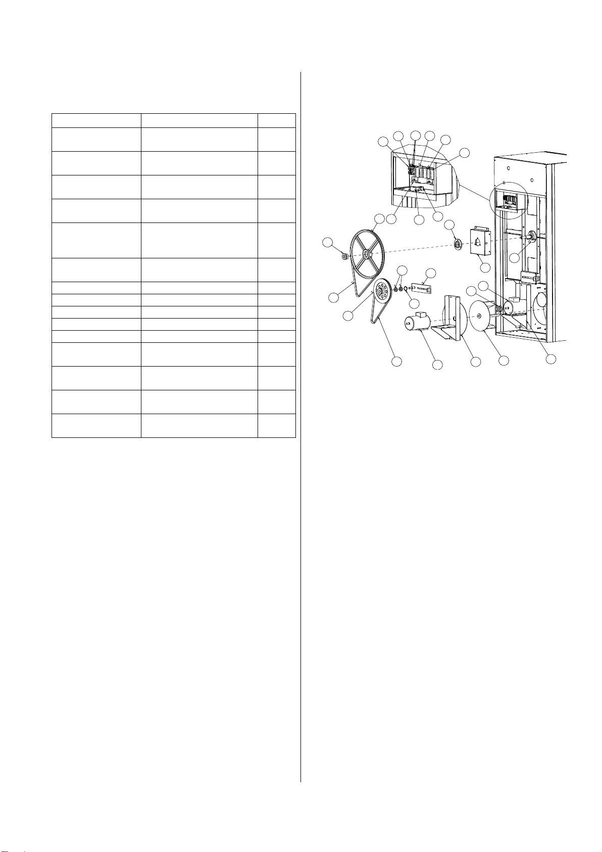
5. MECHANICAL INSTALLATION
Check the exploded view on the right:
a) Unscrew the snub pulley support
(position 8).
b) Unscrew the regulation screw of the
snub pulley support (position 8)
c) Take off the transmission belt
(position 5) which connects the fan
motor (position 26) with the snub
pulley (position 6)
d) Mount the pulley (position 4) on the
motor tree (position 3) and close it
with the apposite dowel.
e) Mount the motor support (position 25)
on the dryer chassis.
f) Fix the motor (position 3) on its
support (position 25).
g) Use the belt (position 5) to connect
the reversing motor pulley (position 3)
to the snub pulley (position 6).
h) Screw the support regulation screw
until the belt is tensioned (position 5)
i) Close the fixing screw of the double
pulley.
6. ELECTRIC INSTALLATION
1) Fix the two B6 contactors on the
omega bar, which is positioned on the
right of the actual fan contactor (which
will be indicated as VE).
2) Mount the two black bridge on the SX
and DX contactor. Check that the
contact position printed on the bridge
are respected.: 1-L1 to 1-L1 (DX); 3-
L2 to 3-L2 (DX); 5-L3 to 5-L3 (DX); 2-
T1 to 2-T1 (DX); 4-T2 to 4-T2 (DX); 6-
T3 to 6-T3 (DX);
3) Fix the thermal relay on the right
contactor (which will be indicated with
DX), inserting the contacts T1, T2 and
T3.
4) Fix the thermal relay at 2,4 A.
5) Using a 1.5 mm2 cable, make the
following power terminal electric
bridge between the VE fan contactor
and the SX contactor.
a) L1 (VE) –T3 (SX)
b) L2 (VE) –T2 (SX)
c) L3 (VE) –T1 (SX)
1
2
26
4
5
6
78
9
10
11 12
13 14
25
3
24
15 16 17 18 21
22
23
19
20
1903KITINE18_02 (E100901B_ENG) 01/02/2016
4
6) Using a more or less 2mt long 4G1.5
cable connect the motor supply
contacts (passing through the cable
holder) with the magneto thermal relay
contact T1, T2 e T3.
To connect the motor use a Y
connection (supply is 3x400V); ground
must be connected with the whole
ground system.
7) Using a 0.5 mm2cable make the
following control electric connection.
a) Neutral connection (blue cable):
make a bridge between contacts:
A1 (VE), A2 (SX), A1 (DX).
b) From contact A2 (DX) with
insulated fork plug to contact 22
(SX) with insulated fork plug
c) From contact 21 (SX) with male
pin, to the connector (drawing I,
ref. 22). On the connector (position
7) it is already present the female
pin which arrives from contact JP9-
5 of the electronic board and which
control right rotation.
d) With insulated fork plug from
contact A1 (SX) to contact 21 (DX)
with insulated fork plug.
e) With insulated fork plug from
contact 22 (DX) to the connector
poisoned on the below side of the
electric board. On the connector
(position 7) it is already present the
female pin which arrives from
contact JP9-5 of the electronic
board and which control left
rotation.
f) Take of the cable from the
contactor 95 of the fan thermal
relay and connect it to the thermal
relay near the DX contactor.
g) Make a bridge between the contact
96 and the thermal relay next to
VE and the contact 95 of the
thermal relay next to DX contactor.
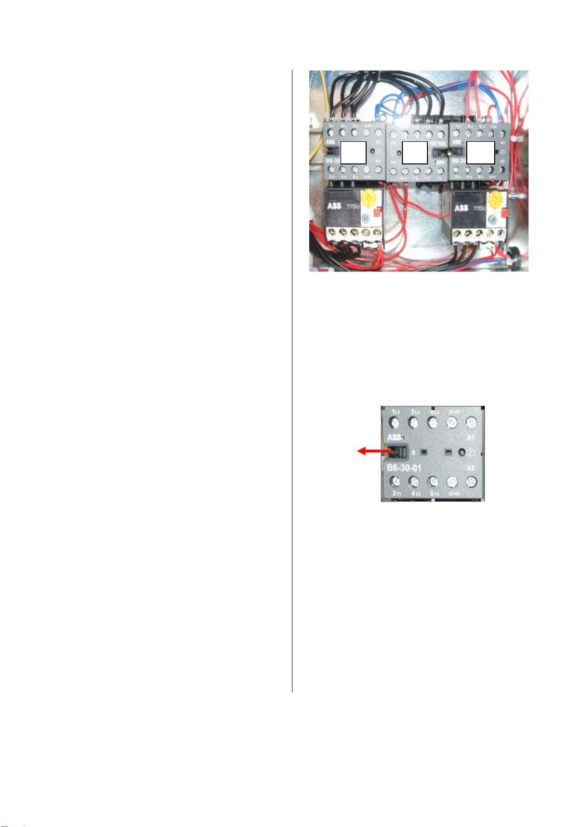
7. WORKING TEST
Each single contactor can be manually
tested. Using a screwdriver pull the
apposite pin until the contacts are closed.
Check the right rotations sense and, in
case, change the position of the two
phases coming out form the contactor.
VE
SX
DX
Other manuals for ES10
2
This manual suits for next models
2
Other Imesa Dryer manuals


Popular Dryer manuals by other brands

Bosch
Bosch WTW85B49SN Installation and operating instructions

Maytag
Maytag MDG-50 installation manual

Mediclinics
Mediclinics M04A Installation and operating manual

Frigidaire
Frigidaire GLGQ642CAS4 Wiring diagram

Eterna
Eterna HDA-1800 Safety and installation instructions

Hanseatic
Hanseatic HWT8A3GT user manual

Frigidaire
Frigidaire AEQ6000ES - AffinityTM 5.8 cu. Ft. Dryer Factory parts catalog

Alliance Laundry Systems
Alliance Laundry Systems Drying Tumbler 70278501R5EN Installation/operation supplement

Frigidaire
Frigidaire FFQE5000QW Features

Samsung
Samsung DV665JS Owner's instructions

Amica
Amica ACD8WH operating instructions

Frigidaire
Frigidaire 134969400A Service manual


