Imesa ES10 Product manual

E980702H 02/12/04
ISTRUZIONI PER L’INSTALLAZIONE E LA MANUTENZIONE ESSICCATOIO
INSTALLATION AND MAINTENANCE GUIDE FOR TUMBLE DRYER
MANUELLE D’INSTALLATION ET DE SERVICE SECHOIR
INSTALLATIONS- UND WARTUNGSANWEISUNGEN FÜR TROCKNER
MANUAL DE PUESTA EN MARCHA Y MANTENIMIENTO SECADORA
IT – GB – IE – FR – DE – AT – CH – ES
IMESA S.p.A.
Via degli Olmi 22
31040 Cessalto (TV), Italia
tel. +39.0421.468011
fax +39.0421.468000
www.imesa.it

E980702H 02/12/04
2
Tab.1
Modello
Model
Modèle
Typ
Modélo
ES10
(TD10) ES14
(TD14) ES18
(TD18) ES23
(TD23) ES34
(TD34) ES55
(TD55)
Diametro cesto
Drum diametre
Diamètre tambour
Trommeldruchmesser
Diámetro tambor
mm 762 762 762 977 977 1202
Profondità cesto
Drum depth
Profondeur tambour
Trommeltiefe
Profundidad tambor
mm 409 579 767 590 870 960
Capacità
Capacity
Capacité
Füllmenge
Capacidad
Kg 10 14 18 23 34 55
Motore elettrico
Electric motor
Moteur électrique
Elektrischer Motor
Motor eléctrico
kW 0.37 0.37 0.37 0.75 0.75 1
Motore inversione
Reversing motor
Moteur inversion
Drehrichtungsmotor
Motor inversion
kW (0.37) (0.37) (0.37) 0.37 0.37 1
Portata aria
Air flow
Débit d’air
Luftwechsel
Caudal de aire
m3/min 10 10 10 20 20 33
Scarico aria
Air exit
Sortie Air
Abluft
Salida aire
Φmm 150 150 150 200 200 300
Larghezza essiccatoio
Dryer width
Largeur séchoir
Trocknerbreite
Ancho secadora
mm 802 802 802 1022 1022 1540
Profondità essiccatoio
Dryer depth
Profondeur séchoir
Trocknertiefe
Profundidad secadora
mm 691 861 1070 950 1220 1700
Altezza essiccatoio
Dryer height
Hauteur séchoir
Trocknerhöhe
Altura secadora
mm 1850 1850 1850 1932 1932 2411
Peso netto
Net weight
Poids net
Netto Gewicht
Peso neto
Kg 203 218 250 280 324 889
E980702H 02/12/04
3
RISCALDAMENTO ELETTRICO / ELECTRIC HEATING / CHAUFFAGE ELECTRIQUE / ELEKTRISCHE
HEIZUNG / CALENTAMIENTO ELETRICO
Tab.2
Modello
Model
Modèle
Typ
Modélo
ES10
(TD10) ES14
(TD14) ES18
(TD18) ES23
(TD23) ES34
(TD34) ES55
(TD55)
Potenza di riscaldamento
Heating power
Puissance chauffage
Heizleistung
Potencia calentamiento
W 6 x 3000 6 x 3000 6 x 4000 6 x 4000 9 x 4000 9 x 6500
Tensione di alimentazione
Power supply voltage
Voltage d’alimentation
Spannung
Voltaje de red de alimentación
AC 400 3N V 50 Hz
Potenza installata
Power
Puissance
Anschlußleistung
Potencia
kW 18 18 24 24.5 36 59.5
Cavo d’allacciamento
Connection wire
Cable de branchement
Anschlußkabel
Cable de conexión
mm25 x 6 5 x 10 5 x 16 5 x 25
RISCALDAMENTO A VAPORE / STEAM HEATING / CHAUFFAGE A VAPOR / DAMPF HEIZUNG /
CALENTAMIENTO VAPOR
Tab.3
Modello
Model
Modèle
Typ
Modélo
ES10
(TD10) ES14
(TD14) ES18
(TD18) ES23
(TD23) ES34
(TD34) ES55
(TD55)
Pressione di esercizio
Working pressure
Pression vapeur
Dampfnenndruck
Presión vapor
Bar 1.5 ÷ 7
Consumo vapore
Steam consumption
Consommation vapeur
Dampfverbrauch
Consumo de vapor
Kg/h 24 ÷ 44 24 ÷ 44 24 ÷ 44 54 ÷ 88 54 ÷ 88 125 ÷ 135
Ingresso vapore
Steam inlet
Entrée vapeur
Dampffanschuß
Entrada vapor
1” 1” ¼
Uscita vapore
Steam outlet
Sortie vapeur
Dampfauslass
Salida vapor
1”
Tensione di alimentazione
Power supply voltage
Voltage d’alimentation
Spannung
Voltaje de red de alimentación
AC 400 3N V 50 Hz
Potenza installata
Power
Puissance
Anschlußleistung
Potencia
kW 0.35 0.4 0.4 0.9 1.0 2
Cavo d’allacciamento
Connection wire
Cable de branchement
Anschlußkabel
Cable de conexión
mm25 x 1.5 5 x 2.5
E980702H 02/12/04
4
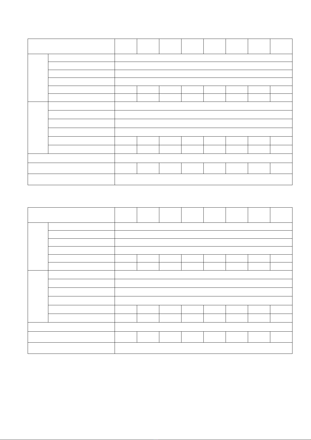
RISCALDAMENTO A GAS / GAS HEATED / CHAUFFAGE A GAZ / GAS HEIZUNG / CALENTAMIENTO GAS
Tab.4
Modello
Model
Modèle
Typ
Modélo
ES10
GAM
(TD10)
ES10
GAB
(TD10)
ES14
GAM
(TD14)
ES14
GAB
(TD14)
ES18
GAB
(TD18)
ES23
GAC
(TD23)
ES34
GAD
(TD34)
ES55
(TD55)
Potenza di riscaldamento
Heating power
Puissance chauffage
Heizleistung
Potencia calentamiento
kW 14.5 29 14.5 29 29 37.8 50.4 87
Capacità (DIN 30682)
Capacity (DIN 30682)
Capacité (DIN 30682)
Füllmenge (DIN 30682)
Capacidad (DIN 30682)
Kg 5.6 7 8.6 11 14 18 26 32
Allacciamento gas
Gas connection
Branchement gaz
Gasanschluß
Conexión gas
R½” R½” R½” R½” R½” R¾” R¾” R1”
Tensione di alimentazione
Power supply voltage
Voltage d’alimentation
Spannung
Voltaje de red de alimentación
AC 400 3N V 50 Hz
Potenza installata
Power
Puissance
Anschlußleistung
Potencia
kW 0.35 0.35 0.4 0.4 0.4 0.9 1.0 2.0
Cavo d’allacciamento
Connection wire
Cable de branchement
Anschlußkabel
Cable de conexión
mm25 x 1.5 5 x 2.5
Tab.5 (ITALIA)
Modello ES10
GAM
(TD10)
ES10
GAB
(TD10)
ES14
GAM
(TD14)
ES14
GAB
(TD14)
ES18
GAB
(TD18)
ES23
GAC
(TD23)
ES34
GAD
(TD34)
ES55
(TD55)
Gas METANO
2H (G20)
Potere calorifero inf. 34.02 MJ/m3
Pressione nominale 2000 Pa
Pressione massima 2500 Pa
Pressione minima 1700 Pa
Ugelli Φmm 1 x 2.90 2 x 2.90 1 x 2.90 2 x 2.90 2 x 2.90 3 x 2.70 4 x 2.70 3 x 4.0
Consumo m3/h 1.53 3.07 1.53 3.07 3.07 4.0 5.33 8.0
Gas LIQUIDO
3+ (G30)
Potere calorifero inf. 45.65 MJ/Kg
Pressione nominale 2800 – 3000/3700 Pa
Pressione massima 3500/4500 Pa
Pressione minima 2000/2500 Pa
Ugelli Φmm 1 x 1.85 2 x 1.85 1 x 1.85 2 x 1.85 2 x 1.85 3 x 1.75 4 x 1.75 3 x 2.7
Consumo Kg/h 1.14 2.29 1.14 2.29 2.29 2.98 3.97 6.0
Tipo B22
Φinterno uscita fumi (mm) 150 150 150 150 150 200 200 300
pressione massima in canna fumaria 150 Pa
E980702H 02/12/04
5
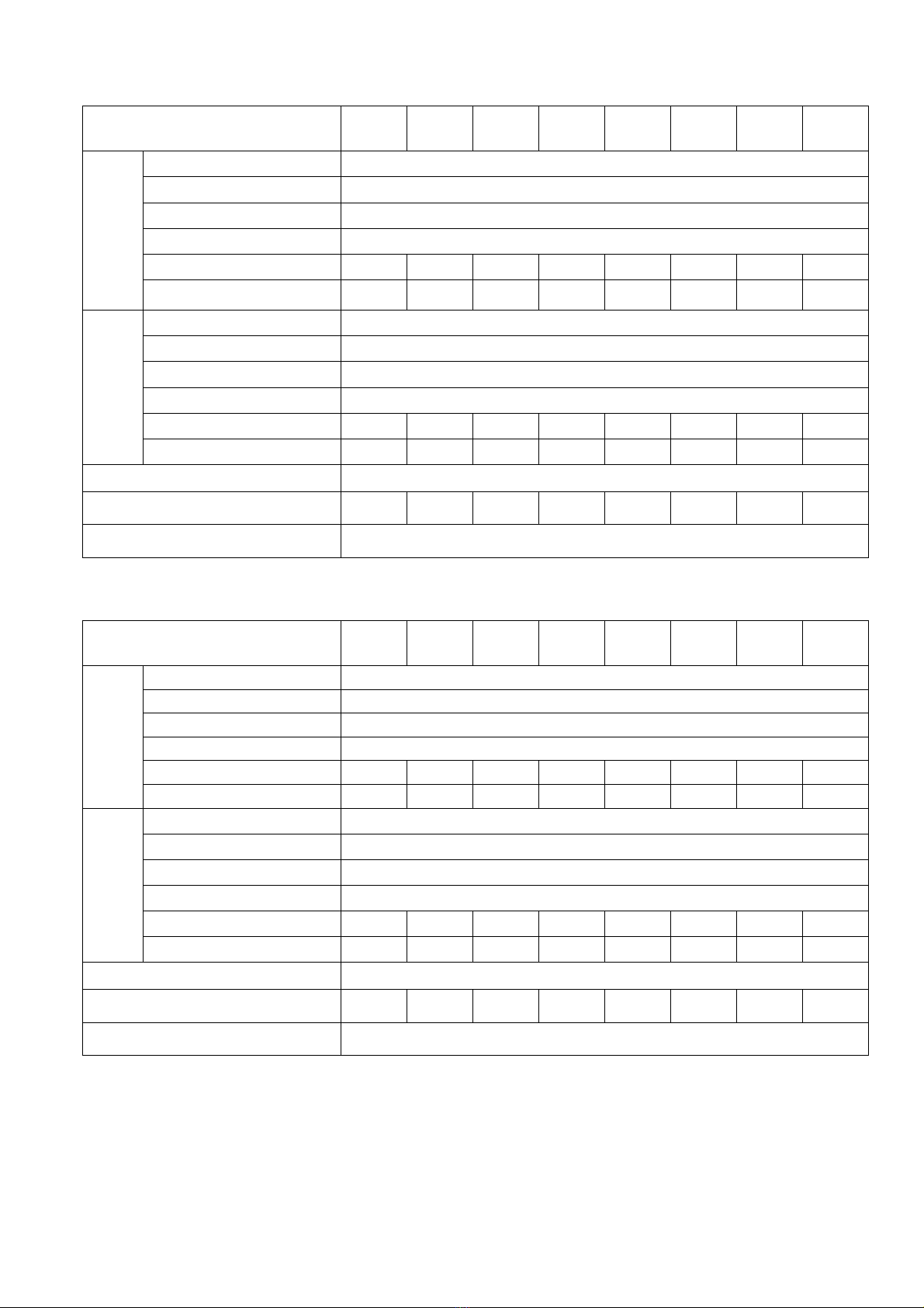
Tab.5 (GREAT BRITAIN)
Model ES10
GAM
(TD10)
ES10
GAB
(TD10)
ES14
GAM
(TD14)
ES14
GAB
(TD14)
ES18
GAB
(TD18)
ES23
GAC
(TD23)
ES34
GAD
(TD34)
ES55
(TD55)
NATURAL GAS
2H (G20)
Low heating power 34.02 MJ/m3
Nominal pressure 2000 Pa
Maximum pressure 2500 Pa
Minimum pressure 1700 Pa
Injectors Φmm 1 x 2.90 2 x 2.90 1 x 2.90 2 x 2.90 2 x 2.90 3 x 2.70 4 x 2.70 3 x 4.0
Consumption m3/h 1.53 3.07 1.53 3.07 3.07 4.0 5.33 8.0
PROPANE GAS
3+ (G30)
Low heating power 45.65 MJ/Kg
Nominal pressure 2800 – 3000/3700 Pa
Maximum pressure 3500/4500 Pa
Minimum pressure 2000/2500 Pa
Injectors Φmm 1 x 1.85 2 x 1.85 1 x 1.85 2 x 1.85 2 x 1.85 3 x 1.75 4 x 1.75 3 x 2.7
Consumption Kg/h 1.14 2.29 1.14 2.29 2.29 2.98 3.97 6.0
Type B22
Φinner exhaust outlet (mm) 150 150 150 150 150 200 200 300
Outlet pipe maximum pressure 150 Pa
Tab.5 (IRELAND)
Model ES10
GAM
(TD10)
ES10
GAB
(TD10)
ES14
GAM
(TD14)
ES14
GAB
(TD14)
ES18
GAB
(TD18)
ES23
GAC
(TD23)
ES34
GAD
(TD34)
ES55
(TD55)
NATURAL GAS
2H (G20)
Low heating power 34.02 MJ/m3
Nominal pressure 2000 Pa
Maximum pressure 2500 Pa
Minimum pressure 1700 Pa
Injectors Φmm 1 x 2.90 2 x 2.90 1 x 2.90 2 x 2.90 2 x 2.90 3 x 2.70 4 x 2.70 3 x 4.0
Consumption m3/h 1.53 3.07 1.53 3.07 3.07 4.0 5.33 8.0
PROPANE GAS
3+ (G30)
Low heating power 45.65 MJ/Kg
Nominal pressure 2800 – 3000/3700 Pa
Maximum pressure 3500/4500 Pa
Minimum pressure 2000/2500 Pa
Injectors Φmm 1 x 1.85 2 x 1.85 1 x 1.85 2 x 1.85 2 x 1.85 3 x 1.75 4 x 1.75 3 x 2.7
Consumption Kg/h 1.14 2.29 1.14 2.29 2.29 2.98 3.97 6.0
Type B22
Φinner exhaust outlet (mm) 150 150 150 150 150 200 200 300
Outlet pipe maximum pressure 150 Pa

E980702H 02/12/04
6
Tab.5 (FRANCE)
Modèle ES10
GAM
(TD10)
ES10
GAB
(TD10)
ES14
GAM
(TD14)
ES14
GAB
(TD14)
ES18
GAB
(TD18)
ES23
GAC
(TD23)
ES34
GAD
(TD34)
ES55
(TD55)
NATURAL GAS
2H (G20)
Puissance calorifique inf. 34.02 MJ/m3
Pression nominal 2000 Pa
Pression maximal 2500 Pa
Pression minimal 1700 Pa
Buses Φmm 1 x 2.90 2 x 2.90 1 x 2.90 2 x 2.90 2 x 2.90 3 x 2.70 4 x 2.70 3 x 4.0
Consommation m3/h 1.53 3.07 1.53 3.07 3.07 4.0 5.33 8.0
PROPANE GAS
3+ (G30)
Puissance calorifique inf. 45.65 MJ/Kg
Pression nominal 2800 – 3000/3700 Pa
Pression maximal 3500/4500 Pa
Pression minimal 2000/2500 Pa
Buses Φmm 1 x 1.85 2 x 1.85 1 x 1.85 2 x 1.85 2 x 1.85 3 x 1.75 4 x 1.75 3 x 2.7
Consommation Kg/h 1.14 2.29 1.14 2.29 2.29 2.98 3.97 6.0
Type B22
Φextèrieur de sortie buées (mm) 150 150 150 150 150 200 200 300
Pression max dans la cheminée 150 Pa
Tab.5 (DEUTCHLAND)
Typ ES10
GAM
(TD10)
ES10
GAB
(TD10)
ES14
GAM
(TD14)
ES14
GAB
(TD14)
ES18
GAB
(TD18)
ES23
GAC
(TD23)
ES34
GAD
(TD34)
ES55
(TD55)
METANGAS
2ELL (G20)
Unterer Heizwert 34.02 MJ/m3
Nenndruck 2000 Pa
Max. Druck 2500 Pa
Min. Druck 1700 Pa
Düse Φmm 1 x 2.90 2 x 2.90 1 x 2.90 2 x 2.90 2 x 2.90 3 x 2.70 4 x 2.70 3 x 4.0
Verbrauch m3/h 1.53 3.07 1.53 3.07 3.07 4.0 5.33 8.0
METANGAS
2ELL (G25)
Unterer Heizwert 29.30 MJ/m3
Nenndruck 2000 Pa
Max. Druck 2500 Pa
Min. Druck 1800 Pa
Düse Φmm 1 x 3.20 2 x 3.20 1 x 3.20 2 x 3.20 2 x 3.20 3 x 3.00 4 x 3.00 3 x 4.5
Verbrauch m3/h 1.78 3.56 1.78 3.56 3.56 4.64 6.19 9.2
FLUSSIGAS
3B/P (G30)
Unterer Heizwert 45.65 MJ/Kg
Nenndruck 5000 Pa
Max. Druck 5750 Pa
Min. Druck 4250 Pa
Düse Φmm 1 x 1.65 2 x 1.65 1 x 1.65 2 x 1.65 2 x 1.65 3 x 1.50 4 x 1.50 3 x 2.3
Verbrauch Kg/h 1.14 2.29 1.14 2.29 2.29 2.98 3.97 5.8
Art B22
ΦInnendurchmesser (mm) 150 150 150 150 150 200 200 300
Max. Gegendruck 150 Pa
E980702H 02/12/04
7
Tab.5 (OSTERREICH)
Typ ES10
GAM
(TD10)
ES10
GAB
(TD10)
ES14
GAM
(TD14)
ES14
GAB
(TD14)
ES18
GAB
(TD18)
ES23
GAC
(TD23)
ES34
GAD
(TD34)
ES55
(TD55)
METANGAS
2ELL (G20)
Unterer Heizwert 34.02 MJ/m3
Nenndruck 2000 Pa
Max. Druck 2500 Pa
Min. Druck 1700 Pa
Düse Φmm 1 x 2.90 2 x 2.90 1 x 2.90 2 x 2.90 2 x 2.90 3 x 2.70 4 x 2.70 3 x 4.0
Verbrauch m3/h 1.53 3.07 1.53 3.07 3.07 4.0 5.33 8.0
FLUSSIGAS
3B/P (G30)
Unterer Heizwert 45.65 MJ/Kg
Nenndruck 5000 Pa
Max. Druck 5750 Pa
Min. Druck 4250 Pa
Düse Φmm 1 x 1.65 2 x 1.65 1 x 1.65 2 x 1.65 2 x 1.65 3 x 1.50 4 x 1.50 3 x 2.3
Verbrauch Kg/h 1.14 2.29 1.14 2.29 2.29 2.98 3.97 5.8
Art B22
ΦInnendurchmesser (mm) 150 150 150 150 150 200 200 300
Max. Gegendruck 150 Pa
Tab.5 (ESPANA)
Modelo ES10
GAM
(TD10)
ES10
GAB
(TD10)
ES14
GAM
(TD14)
ES14
GAB
(TD14)
ES18
GAB
(TD18)
ES23
GAC
(TD23)
ES34
GAD
(TD34)
ES55
(TD55)
NATURAL GAS
2H (G20)
Potencia calorifica inf. 34.02 MJ/m3
Presión nominal 2000 Pa
Presión maxima 2500 Pa
Presión minima 1700 Pa
Inyector Φmm 1 x 2.90 2 x 2.90 1 x 2.90 2 x 2.90 2 x 2.90 3 x 2.70 4 x 2.70 3 x 4.0
Consumo m3/h 1.53 3.07 1.53 3.07 3.07 4.0 5.33 8.0
PROPANE GAS
3+ (G30)
Potencia calorifica inf. 45.65 MJ/Kg
Presión nominal 2800 – 3000/3700 Pa
Presión maxima 3500/4500 Pa
Presión minima 2000/2500 Pa
Inyector Φmm 1 x 1.85 2 x 1.85 1 x 1.85 2 x 1.85 2 x 1.85 3 x 1.75 4 x 1.75 3 x 2.70
Consumo Kg/h 1.14 2.29 1.14 2.29 2.29 2.98 3.97 6.0
Tipo B22
Φinteriot de salida humos (mm) 150 150 150 150 150 200 200 300
Presión max en la chimenea 150 Pa
E980702H 02/12/04
8
Tab.5 (SVIZZERA / SWITZERLAND / SWISSE)
Typ ES10
GAM
(TD10)
ES10
GAB
(TD10)
ES14
GAM
(TD14)
ES14
GAB
(TD14)
ES18
GAB
(TD18)
ES23
GAC
(TD23)
ES34
GAD
(TD34)
ES55
(TD55)
Gas METANO
METAN GAS
Gas de VILLE
2H (G20)
Potere calorifero inf.
Unterer Heizwert
Puissance calorifique inf.
34.02 MJ/m3
Pressione di alim.
Speisungsdruck
Pression d’alimentation
2000 Pa
Pressione massima
Max. Druck
Pression maximal
2500 Pa
Pressione minima
Min. Druck
Pression minimal
1700 Pa
Ugelli
Düse Φmm
Buses
1 x 2.90 2 x 2.90 1 x 2.90 2 x 2.90 2 x 2.90 3 x 2.70 4 x 2.70 3 x 4.0
Consumo m
3
/h
Verbrauch m3/h
Consommation
1.53 3.07 1.53 3.07 3.07 4.0 5.33 8.0
Gas LIQUIDO
FLUSSIGAS
GAS PROPANE
3B/P (G30)
Potere calorifero inf.
Unterer Heizwert
Puissance calorifique inf.
45.65 MJ/Kg
Pressione di alim.
Speisungsdruck
Pression d’alimentation
5000 Pa
Pressione massima
Max. Druck
Pression maximal
5750 Pa
Pressione minima
Min. Druck
Pression minimal
4250 Pa
Ugelli
Düse Φmm
Buses
1 x 1.65 2 x 1.65 1 x 1.65 2 x 1.65 2 x 1.65 3 x 1.50 4 x 1.50 3 x 2.3
Consumo Kg/h
Verbrauch Kg/h
Consommation Kg/h
1.14 2.29 1.14 2.29 2.29 2.98 3.97 5.8
Tipo
Art
Type
B22
Φesterno uscita fumi (mm)
ΦAußendurchmesser (mm)
Φextèrieur de sortie buées (mm)
150 150 150 150 150 200 200 300
Pressione max in canna fumaria
Max. Gegendruck
Pression max. dans la cheminée
150 Pa

E980702H 02/12/04
9
Tab. 6
Model 99010 ES 10 GAM 14 GAM 10 GAB 14 GAB 18 GAB 23 GAC 34 GAD ES 55
Portata aria m³/min a scarico
libero
Free outlet air flow m³/min
Débit d’air avec tuyau libre
m³/min
Luftdruchsatz frei ausblasend
m³/min
Caudal de aire con tubo libre
m³/min
20 20 20 20 20 29 28 33
Contropressione ammessa (Pa)
Allowed ack pressure (Pa)
Contrepression permis (Pa)
Zulassiger Gegendruck (Pa)
Contrapresión permitida (Pa)
+150 +150 +150 +150 +150 +150 +150 +150
Max. temperatura allo scarico
(°C)
Outlet max. temperature(°C)
Température max. à la sortie
(°C)
Max. Abgas-Abluft Temperatur
(°C)
Temperatura max. de salida (°C)
90 90 90 90 90 90 90 90
Manicotto di scarico – Ф(mm)
Outlet pipe – Ф(mm)
Tuyau de sortie – Ф(mm)
Abluftstutzen – Ф(mm)
Tubo de salida – Ф(mm)
150 150 150 150 150 200 200 300
Potenza termica nominale (kW)
Nominal Thermal power (kW)
Puissance thermique nominal
(kW)
Nennwarmebelastung (kW)
Potencia térmica nominal (kW)
14,5 14,5 29 29 29 37,8 50,4 87
La ditta costruttrice declina ogni responsabilità per le possibili inesattezze contenute nel presente manuale
imputabili ad errori di stampa o trascrizione. Si riserva il diritto di apportare ai propri prodotti quelle modifiche
che ritenesse necessarie o utili, senza pregiudicarne le caratteristiche essenziali. E’ vietata la riproduzione
anche parziale, di testi o immagini del presente manuale, senza la preventiva autorizzazione della ditta
costruttrice.
The manufacturer is not responsible for errors contained in the present guide due to wrong edition or
transciption. He has the right to alter products according to changes he may consider necessary or useful
without any modification of the machine main characteristics. Partial or complete copies of this guide are
forbidden, without previous manufacturer authorisation.
Le constructeur n’est pas responsable pour èventuelles inexactitudes écrites dans ce manuelle que peuvent
être dues à des fautes d’imprimerie ou de transcription. Il a le droit de modifier les produits selon les
changements qui il croit necessaires ou utiles, sans changer les caractéristiques essentielles. Il est interdit la
reproduction total ou partielle de images et textes de ce manuelle sans l’authorisation du constructeur.
Der Hersteller lehnt jede Verantwortung für die möglichen Ungenauigkeiten ab, die von Druckfehlern
abhängen. Der Hersteller behält sich das Recht vor, an den Produkten die notwendigen oder nutzlichen
Änderungen durchzuführen, die die hauptsächlichen Eigenschaften des Produktes nicht beeintrachtigen.
Jede Vervielfaltigung von Texten, Textteilen oder Abbildungen des vorliegenden Handbuchs ohne die
vorherige Genehmigung des Herstellers ist verboten.
El constructor no está responsable de las inexactitudes escritas en esto manual debidas a errores de prensa
o de transcripción. El a el derecho de modificar los productos según los cambios que el cree necesarios o
utiles, sin cambiar las características esenciales. La reproducción partial o total de esto manual está
prohibida, si hecha sin la autorización del constructor.

E980702H 02/12/04
10
ITALIANO Pagina ENGLISH Page FRANCAISE Page
1 Informazioni
perl’installazione
13 1 Information on
installation
17 1Reinsegnements
d’installation
21
1.1 Collegamenti elettrici 13 1.1 Electric connection 17 1.1 Branchement
electrique
21
1.2 Collegamento vapore 14 1.2 Steam connection 18 1.2 Branchement de le
vapeur
22
1.3 Collegamento gas 14 1.3 Gas connection 18 1.3 Branchement gaz 22
1.3.1 Prova di tenuta 14 1.3.1 Tightness test 18 1.3.1 Essai d’etncheite 22
1.4 Evacuazione e
scarico dei gas
combusti
14 1.4 Exhaust outlet 18 1.4 Evacuation des fumes 22
1.5 Funzionamento con
potenza termica
prevista
14 1.5 Operation at preset
thermal power
18 1.5 Mise en marche avec
prevue puissance
thermique
22
1.6 Messa in funzione e
collaudo
15 1.6 Operation and test 18 1.6 Mise en marche et
essai
22
1.7 Indicazioni importanti
per l’utente
15 1.7 Notes for the user 19 1.7 Renseignements pour
l’usager
23
2 Allarmi 15
2 Alarms 19
2Signals d’alarme 23
3 Manutenzione 16
3 General maintenence 20 3Entretien 23
4 Controllo del
pressostato del gas
16 4 Gas gauging sensor
test
20 4Systeme de controle
automatique de
pression
24
5 Controllo pressostato
dell’aria
16 5 Pressostat test 20 5Pressostat 24
6 Sicurezza in caso di
sovratemperatura.
16 6 Safety device in case of
overheating.
20 6Surete dans le cas de
surtemperature.
24
7 Figure 33
7 Drawings 33
7Figures 33
DEUTSCH Seite ESPANOL Pagina
1 Installationsanweisun
gen
25 1 Informaciones de
instalacion
29
1.1 Elektrischer aschluss 25 1.1 Conexion electrica 29
1.2 Dampfanschluss 26
1.2 Conexion de vapor 30
1.3 Gasanschluss 26
1.3 Conexion gas 30
1.3.1 Dichtungkontrolle 26
1.3.1 Prueba de
estanqueidad
30
1.4 Abgasung 26 1.4 Evacuationes de vahos 30
1.5 Betrieb mit
vorgesehner
Wärmeleistung
26 1.5 Empleo con potencia
termica preajustada
30
1.6 Inbetriebnahme und
nachprufung
27 1.6 Puesta en marcha y
ensaye
31
1.7 Wichtige
anweisungen fur den
bediener
27 1.7 Importantes
informaciones para el
utilizador
31
2 Alarmsignalien 27
2 Alarmas 31
3 Wartung 28
3 Mantenimiento general 31
4 Kontrolle des
Gasdruckwächters
28 4 Ensayo del detector de
presion gas
32
5 Kontrolle des
Luftdruckwächters
28 5 Ensayo del pressostato
del aire
32
6 Sicherheitsmaßname
bei Überheizung.
28 6 Dispositivo de
seguridad de
sobretemperatura
32
7 Abbildungen 33
7 Illustraciones 33

E980702H 02/12/04
11
1 INFORMAZIONI PER L’INSTALLAZIONE
L’installazione va effettuata da tecnici autorizzati
secondo il rispetto delle normative e dei
regolamenti locali. In assenza di normative,
l’installazione deve essere conforme agli standard
CE applicabili.
L’essiccatoio deve essere installato su un solido
pavimento in grado di sopportarne il peso riportato
sui dati di targa. La macchina è provvista di
quattro piedini dotati di vite di regolazione per il
corretto posizionamento della macchina stessa in
bolla.
Devono essere mantenute opportune distanze per
gli interventi di manutenzione ordinaria e
straordinaria (vedi fig.4 pag.33).
L’ambiente in cui è installata la macchina deve
avere un sufficiente ricambio d’aria: l’essiccatoio
deve scaricare l’aria umida all’esterno.
La macchina deve essere installata in un
ambiente ben aerato: nello stesso ambiente non
devono essere installate macchine che funzionino
a percloro. Nella combustione si formano vapori di
acido cloridrico che possono danneggiare
biancheria e macchinari.
In caso di installazione di essiccatoi alimentati a
gas liquido in locali sotto livello del terreno, si
devono prevedere adeguati dispositivi di
ventilazione forzata.
Ogni attrezzatura professionale con riscaldamento
a gas deve essere considerata,
indipendentemente dalla portata, apparecchio a
gas.
L’aerazione del locale è ottimale, anche nel caso
in cui i gas combusti vengono aspirati
meccanicamente, quando l’inquinamento termico
nominale di questi apparecchi a gas non da luogo
ad alcuna depressione. Così è garantito che
hanno luogo una regolare combustione del gas ed
un completo scarico dei gas combusti.
La verifica di un sufficiente ricambio d’aria va
condotta secondo le norme vigenti.
Le aperture per l’areazione e la ventilazione del
locale possono essere chiudibili solo se la
condizione di apertura è controllata e se
l’esercizio delle fonti di fuoco degli apparecchi a
gas è possibile solo in condizione di apertura.
Non avvicinarsi alla macchina con materiale
infiammabile o prodotti combustibili.
Non caricare la macchina con tessuti
precedentemente immersi in prodotti infiammabili:
tali tessuti devono essere prima accuratamente
risciacquati o messi all’aria.
Tenere qualunque prodotto chimico fuori dalla
portata dei bambini.
Informazioni sulla rumorosità: in osservanza alla
ordinanza sull’informazione riguardante il rumore
emesso da macchine, del 18 Gennaio 1991, si
precisa che l’apparecchiatura in questione ha una
rumorosità contenuta entro gli 80 dB.
Prima di posizionare e collegare l’apparecchiatura
accertarsi che le erogazioni presenti (elettricità,
vapore e gas) siano corrispondenti ai dati di targa.
La targa delle caratteristiche è posizionata sul
retro dello sportellino superiore (vedi fig.1 pag.31).
Durante l’installazione si devono osservare le
seguenti prescrizioni:
- Ordinamento edilizio comunale e/o territoriale
e prescrizioni antincendio.
- Prescrizioni antinfortunistiche vigenti.
- Disposizioni CEI riguardanti gli impianti
elettrici.
- Legge n. 1083 del 06.12.71 “Norme per la
sicurezza dell’impiego di gas combustibile”.
- Norme UNI-CIG 7129/72 ed UNI-CIG 7131/72
“Norme per impianti a gas alimentati dalla rete
di distribuzione o gas GPL”.
- Regolamentazioni dell’ente o società che
erogano o forniscono il gas.
- Disposizioni dell’ente che fornisce l’energia
elettrica.
- Altre eventuali prescrizioni locali.
Rimuovere completamente i residui
dell’imballaggio e la pellicola protettiva da tutte le
superfici.
Per un eventuale fissaggio al pavimento,
richiedere al produttore gli opportuni adattatori
(fig.6 pag.34).
In caso di guasti oppure di anomalie di
funzionamento, spegnere immediatamente
l’apparecchiatura!
1.1 COLLEGAMENTI ELETTRICI.
Tutti gli essiccatoi sono dotati sul pannello
posteriore di una serie di morsetti sui quali
l’installatore deve realizzare gli unici collegamenti
elettrici: il cavo multipolare di alimentazione,
opportunamente dimensionato (vedi tabelle 2, 3 e
4 pag. 3 e 4), deve essere fatto passare
attraverso il pressacavo sul retro della macchina
(fig.2 pag.31 rif. FL) e collegato ai contatti di tali
morsetti.
I morsetti sono:
- tre di colore grigio per le fasi (L1; L2; L3)
- uno di colore blu per il neutro (N)
- uno di colore giallo-verde per la terra
Il conduttore di terra deve essere più lungo degli
altri conduttori, in modo che, in caso di forte
trazione o rottura del fermacavo, si scolleghi solo
dopo i conduttori di tensione.

E980702H 02/12/04
12
Per quanto riguarda l’impianto da realizzare a
monte di ogni singola macchina, l’installatore deve
prevedere un interruttore magnetotermico, avente
una distanza tra i contatti di almeno 3 mm per
ogni polo, ed uno differenziale (salvavita).
L’interruttore onnipolare deve trovarsi nelle
vicinanze dell’apparecchio ed essere in una
posizione facilmente accessibile dall’utente.
E’ obbligatorio collegare la macchina all’impianto
di terra: il costruttore declina ogni
responsabilità qualora questa norma
antinfortunistica non venga rispettata.
Una volta collegata la macchina verificare,
aprendo la porta del filtro, che la ventola di
aspirazione ruoti in senso orario: nel caso in cui
dovesse ruotare in senso inverso disinserire
l’alimentazione dalla rete ed invertire due fasi
sulla morsettiera.
L’essiccatoio deve essere inoltre compreso in un
sistema equipotenziale. Questo collegamento si
effettua allacciando all’apposito morsetto, posto
sulla parte posteriore dell’essiccatoio e
contrassegnato dal simbolo internazionale, un
conduttore avente una sezione nominale sino a
10 mm2. Il collegamento avviene tra tutte le
apparecchiature adiacenti poste nel locale e
l’impianto di dispersione dello stabile.
1.2 COLLEGAMENTO VAPORE
Se la macchina funziona con riscaldamento a
vapore , realizzare gli opportuni collegamenti
all’impianto di generazione e di recupero del
vapore (fig.2 pag.32: rif. JC per l’ingresso, rif. HB
per l’uscita). L’installatore deve prevedere uno
scaricatore di condensa a valle della macchina,
più un filtro ed una saracinesca all’ingresso della
batteria del vapore per preservarne la funzionalità,
e facilitare la successiva manutenzione della
macchina stessa. Il flusso del vapore nella
batteria è continuo e la macchina non prevede
l’uso di una elettrovalvola di ingresso del fluido.
1.3 COLLEGAMENTO GAS
Se la macchina funziona con riscaldamento a gas,
realizzare gli opportuni collegamenti con
l’impianto di distribuzione (fig.2 pag.32, rif. KD):
verificare i dati di targa della macchina, ed in
particolar modo la pressione del gas di
alimentazione .
L’impianto di distribuzione del gas deve essere
fatto secondo le prescrizioni vigenti e con sezioni
e pressioni adeguate all’apparecchio, vedi tabella
5 pag.4 - 8.
A monte dell’apparecchio deve essere disponibile
un rubinetto d’intercettazione gas di tipo ad
intercettazione rapida. Questo deve
assolutamente corrispondere alle prescrizioni
vigenti ed essere omologato.
Il rubinetto d’intercettazione del gas deve trovarsi
nelle vicinanze dell’apparecchio ed essere in una
posizione facilmente accessibile dall’utente.
L’impianto deve essere progettato ed eseguito in
opera secondo le normative vigenti. L’attacco per
il gas sull’essiccatore è R ½” (ES10/TD10,
ES14/TD14, ES18/TD18) e R ¾” (ES23/TD23,
ES34/TD34); questa sezione non deve
assolutamente essere ridotta.
Il collegamento all’impianto di adduzione gas può
essere di tipo fisso oppure scollegabile; qualora si
impiegassero dei tubi flessibili, questi devono
essere di acciaio inox DIN 3384 o DIN 3383.
1.3.1 PROVA DI TENUTA
Tutti i raccordi fra impianto ed apparecchio sono
da sottoporre ad una prova di tenuta. Per questa
operazione si consiglia l’utilizzo di spray
cercafughe; altrimenti si possono spennellare con
altre sostanze schiumose, che non provocano
corrosione, i punti di raccordo; con entrambe le
soluzioni non devono verificarsi bolle.
È assolutamente vietato impiegare fiamme
libere per la prova di tenuta!
1.4 EVACUAZIONE E SCARICO DEI GAS
COMBUSTI
Gli essiccatoi con funzionamento a gas sono
apparecchi a gas del tipo B22, cioè apparecchi a
gas dipendenti da un ambiente aerato senza
dispositivo di protezione al vento con soffiante
dietro la camera di combustione.
I gas combusti di un essiccatoio a gas devono
essere assolutamente condotti all’aperto
attraverso il camino.
La condotta dei gas combusti, possibilmente
corta, va inclinata in forma ascendente verso il
camino di scarico.
Nel punto più basso va previsto uno scaricatore di
condensa e la derivazione di tale scaricatore deve
osservare le disposizioni locali per l’allacciamento
allo scarico d’acqua.
La condotta per lo scarico dei gas combusti deve
essere a tenuta stagna e deve essere adatta allo
scarico di aria calda umida (al manicotto di
scarico c’è una sovrapressione fino a circa 1.5
mBar),
vedi tab.6 pag.9.
1.5 FUNZIONAMENTO CON POTENZA
TERMICA PREVISTA
Tutte le apparecchiature durante il collaudo finale
in fabbrica vengono predisposte per il tipo di gas
riportato sulla targhetta adesiva situata vicino alla
targa delle caratteristiche (vedi fig.1 pag.31).
Qualora la predisposizione dell’apparecchio non
corrispondesse alla famiglia di gas disponibile in
loco è obbligatorio eseguire una trasformazione
dell’apparecchio per l’adeguamento al tipo di gas
presente. In questo caso è assolutamente
necessario informare il servizio di Assistenza
Tecnica
La messa in funzione dell’apparecchio con la
potenza termica prevista dipende dalla pressione
in entrata e dal potere calorifico del gas nonché

E980702H 02/12/04
13
dall’ugello, dalla pressione allo stesso e dal
corretto apporto di aria primaria.
La pressione in entrata che permette il
funzionamento dell’apparecchio è compresa per i
vari tipi di gas nei limiti riportati in tabella 5. Al di
fuori di questi limiti è vietata la messa in funzione
dell’apparecchio. Qualora si riscontrasse una
pressione differente da quanto riportato in tabella
si consiglia di interpellare l’ente o la società che
erogano il gas oppure la ditta che ha effettuato
l’impianto.
Il potere calorifico inferiore del gas si richiede
all’ente o la società che eroga il gas e dovrebbe
corrispondere a quanto riportato in tabella 5 pag.
4 - 8.
Controllo della pressione di entrata.
La pressione di entrata va misurata con uno
strumento di misurazione liquida o digitale
(risoluzione di almeno 0.1 mBar).
Chiudere il dispositivo di intercettazione.
Allentare la vite di tenuta della presa di
pressione della valvola del gas (fig.3 pag.33).
Collegare il manometro.
Aprire il dispositivo di intercettazione.
Mettere in funzione l’apparecchio secondo le
istruzioni d’uso.
Misurare la pressione di entrata, con il
bruciatore acceso.
Spegnere l’apparecchio.
Chiudere il dispositivo di intercettazione.
Staccate il manometro.
Chiudere la vite di tenuta della presa di
pressione della valvola del gas e controllare la
tenuta.
Aprire il dispositivo di intercettazione e
controllare la tenuta.
La messa in esercizio dell’apparecchio a gas non
è ammessa al di fuori degli intervalli di pressione
riportati in Tab.5 pag. 4 - 8.
1.6 MESSA IN FUNZIONE E COLLAUDO
Non appena terminati i lavori di allacciamento, è
da controllare l’apparecchio e tutta l’installazione.
Si deve controllare ad esempio:
- che non vi siano ancora residui di pellicola di
protezione sulle pareti esterne.
- che i collegamenti siano effettuati secondo le
prescrizioni e le indicazioni del presente
manuale.
- che siano soddisfatte tutte le prescrizioni di
sicurezza delle norme, leggi e direttive vigenti.
- che i collegamenti gas ed acqua effettuati
siano a tenuta.
Si procede poi all’accensione dell’apparecchiatura
secondo le istruzioni del manuale d’uso
controllando l’accensione progressiva dei
bruciatori e l’aspetto della fiamma.
Richiudere lo sportello.
Per una maggiore sicurezza di buon
funzionamento si consiglia di effettuare un
controllo del consumo di gas, questo può essere
fatto con il metodo volumetrico. Rilevando
attraverso il contatore quanto gas è stato
consumato in una determinata unità di tempo, il
valore che risulta è da confrontare con i valori
riportati nella tabella 5.
1.7 INDICAZIONI IMPORTANTI PER L’UTENTE
Con il manuale d’uso alla mano spiegare
all’utente le funzioni, le sicurezze, l’uso
appropriato e, soprattutto, gli intervalli per la
manutenzione dell’apparecchiatura.
La manutenzione, che comprende la pulizia dei
bruciatori, il controllo della camera di combustione
e la pulizia dei vari condotti deve essere effettuata
almeno una volta all’anno, a tale scopo si
consiglia la stipula di un contratto di
manutenzione.
Sensibilizzare l’utente sul fatto che ogni intervento
di riparazione o manutenzione, che si rende
necessario nel tempo, deve essere effettuato solo
da un servizio di assistenza tecnica autorizzato.
Informare l’utente che in caso di guasto o
anomalia di funzionamento sono da interrompere
immediatamente tutte le erogazioni (elettricità,
vapore e gas).
Il manuale d’installazione e lo schema elettrico
sono da conservare per eventuali interventi.
Sensibilizzare l’utente che il manuale d’uso fornito
con l’apparecchiatura deve essere conservato in
modo visibile nelle vicinanze della stessa. Sul
manuale d’uso è bene riportare il nominativo del
servizio di Assistenza Tecnica di fiducia.
Sensibilizzare l’utente sul fatto che certe anomalie
di funzionamento sono spesso causate da errori
d’uso per esempio erogazioni chiuse, pertanto è
bene addestrare in modo corretto il personale di
servizio sull’uso e sul funzionamento
dell’apparecchio. Anomalie ricorrenti necessitano
dell’intervento del servizio di Assistenza.
Fare, inoltre, presente, che modifiche al locale
d’installazione, variazioni di areazione
dell’ambiente, possono influenzare la
combustione ed è pertanto consigliabile fare
eseguire un controllo delle funzioni
dell’apparecchiatura.
2 ALLARMI
Si dà di seguito un elenco dei possibili allarmi che
possono bloccare la macchina.
“DEPRESSION”: All’avviamento della batteria di
riscaldamento, non si è creata sufficiente
depressione all’interno dell’essiccatoio.
L’Assistenza Tecnica deve verificare:
1) il corretto senso di rotazione della ventola.
2) i corretti collegamenti del pressostato (elettrici
e pneumatici).
3) il corretto funzionamento del pressostato.
“PORTA APERTA”: E’ stato aperto l’oblò.
Richiudere l’oblò e premere START per riavviare il
programma o STOP per interromperlo. Se il

E980702H 02/12/04
14
segnale persiste, anche quando la porta è invece
chiusa, spegnere la macchina, togliere tutte le
alimentazioni e chiamare il servizio di Assistenza
Tecnica che deve verificare:
1) i corretti collegamenti del microinterruttore
porta ed il suo funzionamento.
“SONDA TEMPER”: La sonda di temperatura
risulta guasta. L’Assistenza Tecnica deve
verificare:
1) L’effettivo collegamento della sonda termica.
2) L’effettivo funzionamento della sonda di
temperatura.
“OVERLOAD”: Uno dei motori si è surriscaldato.
L’Assistenza Tecnica deve eseguire le seguenti
verifiche:
1) verificare i morsetti del motore.
2) verificare la tensione di alimentazione.
“GAS”: E’ un segnale che può apparire solo nelle
macchine alimentate a gas. Sono falliti tre tentativi
consecutivi di accensione del bruciatore.
L’Assistenza Tecnica deve verificare:
1) Il funzionamento della centralina di
accensione, della candeletta di accensione e
della sonda di ionizzazzione.
“PRESS GAS”: E’ un segnale che può apparire
solo nelle macchine alimentate a gas; si è avuta
una caduta di pressione nell’alimentazione del
gas. L’Assistenza Tecnica deve verificare:
1) la pressione di alimentazione del gas.
Qualunque caso di guasto deve sempre essere
verificato e risolto dal servizio di assistenza
tecnica specializzato.
3 MANUTENZIONE
La manutenzione della macchina deve essere
eseguita esclusivamente da personale qualificato:
qualunque tipo di operazione sulla macchina deve
essere eseguita esclusivamente dopo aver
staccato l’alimentazione elettrica, e, se esistente,
del gas o del vapore.
Si dovranno eseguire con regolarità le seguenti
operazioni di manutenzione ordinaria.
OGNI 6 MESI: Ispezionare cerniere, viti, dadi,
grani della cuscinetteria e collegamenti
dell’impianto gas o del vapore.
Ispezionare la messa a terra elettrica
dell’essiccatoio.
Ispezionare i collegamenti del motore e lo stato di
logorio delle cinghie di trasmissione.
Ispezionare tutti i collegamenti elettrici.
Ispezionare con cura tutti i dispositivi di sicurezza.
OGNI ANNO: Si consiglia di sottoporre
l’apparecchio ad una verifica, almeno una volta
all’anno; allo scopo è opportuno stipulare un
contratto di Assistenza.
4 CONTROLLO DEL PRESSOSTATO DEL GAS
Il pressostato del gas viene regolato dal
produttore ad un livello di 20 mBar di pressione, e
viene sigillato. Non è permesso manomettere il
pressostato.
5 CONTROLLO PRESSOSTATO DELL’ARIA
Il pressostato dell’aria viene impostato dal
produttore del componente e non è modificabile.
6. SICUREZZA IN CASO DI
SOVRATEMPERATURA.
Nel caso in cui la temperatura all’interno del
bruciatore raggiunga valori troppo elevati, una
pastiglia termostatitca di sicurezza arresta il
funzionamento del sistema di riscaldamento: il
cesto continua a ruotare ma il bruciatore non si
accende. La pastiglia termostatica è a riarmo
manuale, quindi, se questo caso si verifica, è
necessario, spegnere la macchina, togliere tutte le
alimentazioni, aprire lo sportellino superiore del
fronte della macchina e premere il pulsante di
colore marrone posto a ridosso della pastiglia
stessa, si veda fig. 7 sottoindicata per le macchine
a gas e per le macchine elettriche (nel caso in cui
sia presente).
Se l’inconveniente si dovesse ripetere, spegnere
la macchina, togliere tutte le alimentazioni e
chiamare il servizio di Assistenza Tecnica.
Fig. 7

E980702H 02/12/04
15
1 INFORMATION ON INSTALLATION.
Installation and maintenance must be performed
by authorised and qualified technicians; they have
to know our products and be acquainted with
European standards for installation of industrial
laundry equipment. In absence of legislation, the
installation must conform applicable CE
standards.
The dryer must be installed on a solid floor
capable of supporting its weight (the machine
weight is indicated on the silver-plated label on
the machine back) The dryer is equipped with four
feet to be screwed to the relative four threaded
holes on the base. The machine must be installed
perfectly in level.
To ease installation and maintenance we
recommend to leave some space around the
machine
(see pict. 4 page 33).
The machine must be installed into an aired room:
the dryer must be vented to the outdoors.
The dryer must be installed in an aired room; it is
forbidden to install the dryer in presence of
machines which work with perchlorate. The
combustion produces chloridric acid fumes which
may damage linen and machines.
If propane heated machines are installed in
basements it is necessary to install adequate
forced ventilation devices.
Gas heated professional equipment must be
considered gas machines without any regard to
their dimensions.
Gas heated machines which need the air of the
room as supporter of combustion must be
installed in rooms where there is an adequate air
circulation with the outdoors.
If the room is vented mechanically, the air
circulation can be considered good when the
machine environmental nominal overheating
produces no depression. This assures the regular
gas combustion and the total exhaust evacuation.
The air circulation testing must be performed
according to measures in force.
The room opening for ventilation may be equipped
only with controlled locking devices which must
remain opened during combustion.
To prevent fire hazard or explosions do not stand
near the machine with explosive or inflammable
products.
It is forbidden to put anything in the machine other
than the items to be dried. Do not load the
machine with fabrics contaminated by dangerous
substances such as explosives, inflammables,
etc. Make sure they are rinsed or aired before
drying.
In accordance to legislation on machine noisiness
dryers’ noisiness is inferior to 80 dB
Before positioning and wiring the dryer, the
installer has to check whether gas, steam and
power supplies conform to machine specifications.
These data are on the inner part of the small door,
in the machine back (see fig. 1 pag.33).
For the machine installation the technician must
respect the following regulations:
- Building and/or territorial regulations and fire-
prevention regulations;
- Accident prevention measures in force;
- CEI regulations on electric installations;
- Gas supplier (either body or company)
regulations;
- Regulations of the power supply company;
- Other local regulations.
Make sure to take off all residual packaging (card
board and cellophane film) form the dryer panels.
In case of mal-functioning or failure, turn off the
machine immediately!
If the machine has to be bolted to the ground, the
installer must ask for adaptors (see pict. 6 page
34).
1.1 ELECTRIC CONNECTION.
All the dryers are equipped with a terminal board
on the back panel; all the electric connections
must be made on this board a duly dimensioned
multipole feed cable (see table 2, 3 and 4 pag. 5
and 6 ) should be inserted in the cable holder
located in the machine rear (see fig.2 pag.34 ref.
FL) and connected to the following terminals:
- three grey terminals (phases: L1; L2; L3);
- one blue terminal (neutre: N);
- one yellow-green terminal (earth).
The earth wire must be longer than the other
wires because it must disconnect after the phases
wires in case of tensile stress or damage of the
cable holder.
With regard to the external electric installation,
each machine should be connected to a single
magneto-thermal switch and power cut-off safety
device.
The multipole feed switch must be placed near the
machine and it must be easily accessible to
installer.
Each machine must be connected to ground: the
manufacturer is not responsible for any
consequence arising from the neglecting of
safety regulations.
Once connected the machine, open the lint door
and control whether the fan turns clockwise:
should it rotate counter-clockwise disconnect the

E980702H 02/12/04
16
power supply and invert two of the three phases
on the terminal board.
Moreover the dryer must be connected to the
unipotential system. The installer must connect an
adequate cable (nominal section up to 10 mm2) to
the pre-set terminal (marked by the international
label) on the machine back. Thus all the machines
are connected to the ground.
1.2 STEAM CONNECTION
For steam heated machines, the installer must
connect them to the external boiler (see pict. 2
page 34, rif. JC inlet, rif. HB outlet.). The
technician must install a trap at the steam exit, a
steam filter and a gate valve on top of the steam
coil in order to ease maintenance and servicing.
Inside the coil the steam flow is continual and
there is no need of a steam inlet electrovalve.
1.3 GAS CONNECTION
For gas heated machines, the installer must
connect them to the gas feeding (see fig.2 pag.34,
rif. KD): control the dryer technical features and in
particular the gas inlet pressure.
The feeding system must conform the regulations
in force. Pipes and gas pressure must be
adequate to dryer features (see table 5 page 4).
On top of the machine there must be gas fast
interception cock. The valve must conform
regulations in force and be certified by an
accredited company.
The interception cock must be placed near the
machine in a position easily accessible to the
operator.
The installation must be designed and carried out
according to standards in force. The dryer gas
connection is R ½” (ES10/TD10, ES14/TD14,
ES18/TD18) or R ¾” (ES23/TD23 and
ES34/TD34), this section cannot be reduced.
The gas feeding pipe can be permanent or not;
flexible pipes must be stainless steel DIN 3384 or
DIN 3383.
1.3.1 TIGHTNESS TEST
All the connections between the gas feeding and
the dryer must be submitted to a tightness test.
We recommend the use of leak finder sprays;
otherwise pipes can be covered with special not-
corrosive foams; in both cases pipes don’t have to
produce bubbles.
It is forbidden the use of fire to inspect gas
connection for leak!
1.4 EXHAUST OUTLET
Gas heated dryers are equipment of B22 type.
These gas heated machines must work in vented
rooms; they are not equipped with wind proof
blower on the burner back. Dryer exhaust must be
led outside through the duct. The duct must be as
short as possible and sloped upwards toward the
chimney. On the lower part of the duct a
condensate trap must be installed and its drain
pipe must be connected to the water drainage
according to rules in force.
The exhaust duct must be perfectly tight and fit to
humid air drainage (the pipe coupling
overpressure can be approximately of 1,5 mBar),
see table 6 page 9.
1.5 OPERATION AT PRESET THERMAL
POWER
During the final testing at our factory machines
are adjusted on the type of gas described on the
label on the machine back panel (see pict.1 page
31).
If the gas feeding differs from the machine gas
type, it is necessary to alter the dryer to conform it
to the new type of gas. In this case the installer
must inform your Technical Department.
At the pre-set thermal power operation depends
on the inlet gas pressure, the gas heating power,
the nozzle, its gas pressure and on the air inlet.
Dryers required gas inlet pressure is reported on
the table 5 page 4. It is forbidden to operate the
machine with pressure not included in the
prescribed range. In case of different pressure we
recommend to contact the local gas company or
the firm which has built the gas installation.
The installer may ask for the minimum heating
power to the gas company; it must correspond to
the one reported in the table 5 page 4.
Survey of the gas inlet pressure
Gas inlet pressure can be gauged connecting a
manometer either with liquid column or digital
(minimum accuracy 0,1 mBar).
Close the interception trap
Unscrew the sealing screw on the pressure
plug of the gas valve, see pict. 3 page 33.
Connect the manometer
Open the interception trap
Start the dryer according to instructions
Gauge the inlet pressure while the burner is
working
Turn off the dryer
Close the interception trap
Disconnect the manometer
Screw the sealing screw on the pressure plug
of the gas valve and check its tightness
Open the interception and check tightness
The starting-up of gas dryers is not allowed when
pressure values differ from ranges reported on
table 5 page 4 .
1.6 OPERATION AND TEST
After connecting the machine, it is important to
test the installation and the machine itself. For
example the installer must check:
- whether there are rests of packaging over the
external panels.
- whether connections conform this manual
instructions.

E980702H 02/12/04
17
- whether the installation conforms all safety
standards and regulations in force.
- whether gas and water connection are
perfectly sealed.
Afterwards the installer has to start the machine
according to manual instructions and inspect the
burners ignition and the flame.
Close the door.
To be sure of the perfect machine functioning we
recommend to test the gas consumption; using
the volumetric system (gas consumption during a
settled time unit). The gauged value must be
compared to the values reported on the
“Technical data” table 5 page 4.
1.7 USER’S NOTES
We recommend to show the user functions and
safety devices of the machine and to explain how
to operate and when to service the machine.
The maintenance (including burner cleaning,
inspection of the combustion chamber and duct
cleaning) must be effected at least once each
year; we recommend to stipulate a contract for
maintenance.
We recommend to inform the user that
maintenance and servicing must be effected by an
authorised assistance service.
We recommend to inform the user that all
connections (power, steam and gas feeding) must
be taken off in case of fault or mal-functioning.
We recommend to keep the machine manual and
electric wiring diagram for future needs. The
manual must be stored near the machine. It may
be useful to write the Assistance service name on
the manual.
We recommend to inform the user that mal-
functioning is often caused by errors of use; for
this reason we recommend to instruct users on
machine operation and functioning. Recurrent
faults require the assistance service intervention.
Furthermore the client must be informed that
changes to the room where machines are
installed may alter dryer combustion and we
recommend to inspect the machine.
2 ALARMS
Please find hereafter a list of the alarms which
stops the machine:
“DEPRESSION”: At the starting -up of the heating
phase there is not enough depression inside the
dryer
The technical assistance must check:
1) Whether the fan rotates in the correct sense.
2) The pressostat connection (either the electric
and the pneumatic one).
3) Whether the pressostat works correctly.
“DOOR OPEN”: The door is opened. Close the
door again and press START to start the program
again or STOP to stop it. If the alarm doesn’t stop,
even if the door is well closed, take off all feeding
connections and call for Assistance, who will
check:
1) Whether the door microswitch works properly
and its connection.
“PROBE FAILURE” The temperature probe is
broken. Assistance must check:
1) The temperature probe connection
2) The probe functioning.
“OVERLOAD”: A motor thermal overload
occurred. The assistance must check:
1) Control the motor terminals.
2) Control power feeding voltage.
“FLAME OFF”: The message displays only on gas
heated machines. If the spark ignitor does not
ignite, after the third attempt of starting-up the
machine the machine stops.
The assistance must check:
1) The spark ignition system, the igniter plug and
the ionisation sensor.
“GAS PRESS”: The message displays only on
gas heated machines. The gas pressure has
decreased abruptly. The assistance must check:
1) The gas feeding pressure.
We recommend to call for authorised technical
assistance every time a failure occurs.
3 GENERAL MAINTENANCE.
Servicing and maintenance of the machine must
be performed only by experienced technicians:
before servicing be sure to take off power supply
and either gas or steam connection according to
the type of heating.
The following operations must be performed
regularly:
6 MONTHS: Inspect door hinge bolts, nuts,
screws, bearing set screws, non permanent gas
or steam connections.
Inspect electrical ground connection to dryer.
Inspect motor and drive belts for wear and/or
adjustments.
Inspect all electric and/or gas connections.
Inspect all safety devices.
1 YEAR: We recommend to perform complete
operational inspection at least once each year.
4 GAS GAUGING SENSOR TEST
The manufacturer sets the gas gauging sensor at
20 mBar and seals it.
It is not allowed to tamper with the gas gauging
sensor.
5 PRESSOSTAT TEST
The pressostat has been set by its manufacturer
and cannot be altered.

E980702H 02/12/04
18
6. SAFETY DEVICE IN CASE OF
OVERHEATING.
If the temperature of the burner becomes too high,
a safety thermostat stops the heating system: the
drum goes on turning, but the burner doesn’t
ignite. The thermostat must be reset manually
therefore in cases such as this you must: take off
all feeding connections, open the upper door on
the machine front and press the brown button on
the thermostat back fig. 7 (see below) for gas
heated machines and (if the thermostat is
installed) on electric heated machines.
If this problem occurs again, switch off gas and
power supply and call Techincal Assistance.
Pict. 7

E980702H 02/12/04
19
1 RENSEIGNEMENTS D’ INSTALLATION
L’installation et l’entretien des machines doivent
être effectués par des installateurs compétents;
l’installateur doit bien connaître nos produits, les
règles locales pour l’installation et en defaut les
applicables règles CE.
Le séchoir doit être installé sur un plancher
horizontal et solide, capable de supporter son
poids (le poids est écrit sur la plaque argentée sur
le panneau postérieur de la machine). Pour la
mise à niveau la machine est pourvue de quatre
pieds de réglage.
Afin de faciliter l’installation et l’entretien nous
recommandons de laisser des distances de
dégagements minimales par rapports aux murs
adjacents
(voir fig.4 pag.35).
Le séchoir doit être installé dans la pièce
correctement ventilée, avec un apport d’air venant
de l’extérieur.
L’installation du séchoir à proximité de machines
fonctionnant avec du perchlorate est totalement
interdite. En effet, la combustion entrainerait alors
la création de vapeur d’acide chlorhydrique qui
endommage les machines et la linge.
Dans le cas que un séchoir raccordé au propane
est installé dans sous-sol, il est nécessaire de
prévoir une ventilation forcée d’air de puissance
adéquate.
Les séchoir à chauffage gaz doivent être
considérés comme des appareils à gaz, quelle
que soit leur puissance.
Le séchoir à gaz utilisent l’air de la pièce
commesupport à la combustion et doivent être
installés dans une pièce avec une ventilation d’air
frais correcte.
Sila pièce dispose d’une ventilation méchanique,
l’apport d’air sera consideré correct si l’élévation
normale de la température liée au fonctionnement
de l’appareil n’entraine pas de mise en dépression
du local. Ceci garanti une combustion régulière et
une évacuation totale des fumées.
Le contrôle de la ventilation devra être effectuée
selon les normes en vigueur.
Si le système d’entrée d’air frais du local est
équipé d’un volet de fermeture contrôlé, celui-ci
devra resté ouvert durant le foctionnement du
séchoir.
L’air de remplecement doit provenir de l’extérieur
et l’échappement du séchoir doit décharger l’air
humide vers l’extérieur.
Pour prèvenir des risques d’incendie ou
d’explosion, les produits infiammables ou
explosifs ne doivent pas être stockés à côté du
séchoir.
Il est interdit de mettre dans le séchoir des
produits autres que le linge à sécher. Ne pas
remplir le tambour avec des articles ayant èté en
contact avec des substances dangereuses,
explosives, inflammables, etc. S’assurer que ce
fibres soient rincèes ou aérées avant séchage.
En conformité avec la législation sur le bruit des
machines, le niveau sonore de fonctionnement
des séchoirs est inférieur à 80 dB.
Avant de mettre en place et brancher le séchoir,
on doit s’assurer si l’existant distribution de gaz,
vapeur ou d’électricité est compatible avec
l’alimentation indiquée dans les données
techniques du séchoir. Le données sont sur la
plaque placée sur la paroi intérieure de la petit
porte derriér (voir fig.1 pag.33).
Pour l’installation on doit respecter les suivants
dispositions:
- Règlements de l’édilité communale et/ou
territoriale et règlements contre les incendies;
- Dispositions pour la prevention des accidents;
- Règlements de l’Institut ou de la Societé du
gaz;
- Règlements de l’Institut ou de la Societé de
l’élecricité;
- Autres règlements locaux.
Enlever tous les rests de emballage et de pellicule
protectrice de panneaux du séchoir.
Pour fixer la machine au sol, demander les
suports de fixage au constructeur (fig. 6 pag.36)
En cas de panne ou anomalie de fonctionnement,
arrêter la machine tous de suite.
1.1 BRANCHEMENT ELECTRIQUE
Tous les séchoirs sont equipés avec un tableau
de bornes, dans la côté postérieure, où
l’installateur doit faire tous les branchements
électriques. L’installateur doit prévoir un cable
multipolaire d’alimentation proportionné (voir
tab.2, 3 et 4 pag. 5 et 6); le cable doit passer au
travers du passe-cable dans la côté postérieure
de la machine et se brancher aux suivants
bornes:
- trois bornes gris (phases: L1,L2,L3);
- un borne bleu (neutre: N);
- un borne jaune-vert de terre.
Le conducteur de terre doit être le plus long que
les autres conducteurs afin que il soit débranché
aprés les conducteurs de tension en cas de
sécousse ou dommage du passe-cable.
En autre le séchoir doit être connecté à un circuit
de branchement protégé de façon indipéndante et
à un disjuncteur de sûreté.
L’ interrupteur multipolaire doit être environ du
séchoir dont on peut arriver facilement.

E980702H 02/12/04
20
Chaque machine doit être branchée à la mise à la
tierre. Le constructeur ne repond pas pour les
consequénces qui derivent de un emploi
inconsidéré et du non respect des normes de
sûreté.
Après que la machine a été branchée, inspecter le
sens de rotation du tambour. Si il tourne dans le le
sens contraire à celui des aiguilles d’une montre,
l’installateur doit débrancher la courant électrique
et inverser deux des phases dans le tableau de
bornes.
En autre la machine doit être branchée à un
systéme équipotentiel. L’installateur doit brancher
un conducteur de section nominal de jusqu’à 10
mm2 au borne correspondant à-l’arriére de la
machine. Le borne est marqué par le symbole
international. En cette façon toutes les machines
installées dans la piéce sont branchée à
l’installation de dispersion de l’établissement.
1.2 BRANCHEMENT DE LA VAPEUR
Si le séchoir chauffe à vapeur (voir fig. 2 pag.34,
rif. JC in rif. HB out), il faut le brancher au
générateur de vapeur. L’installateur doit prevoir
un déchargeur de condensation au bout de la
machine, un filtre pour la vapeur et une vanne
d’entrée au début de la batterie de vapeur pour
faciliter l’entrétien de la machine. Le débit de
vapeur dans la batterie est continu et
l’electrovanne d’entrée vapeur n’est pas prevue.
1.3 BRANCHEMENT GAZ
Si le séchoir chauffe à gaz, il faut le brancher à
l’installation de distribution gaz (voir fig.2 pag.34
rif. KD): nous recommendons de contrôler les
données techniques du séchoir et en particulier la
pression d’entrée du gaz de l’alimentation.
L’installation de distribution du gaz doit être
conforme aux règlements en vigueur; les sections
des tuyaux et la pression doivent être
proportionnés à la machine (voir la tableau 5 pag.
8 et 10).
Au début de la machine il faut prevoir une vanne
d’interception gaz rapide. La vanne doit être
homologuée et conforme aux règlements en
vigueur.
La vanne d’interception doit être placée près de la
machine dans une position facilement accesible.
L’installation doit être projetée et éxecutée selon
les règlements en vigueur. La prise de gaz du
séchoir a une section de R ½” (ES10/TD10,
ES14/TD14, ES18/TD18) ou R ¾” (ES23/TD23,
ES34/TD34), que ne doit pas être réduite.
Le branchement à l’installation de distribution de
gaz peut être fixe ou amovible; en faisant usage
de tuyaux flexibles, ils doivent être en acier
inoxidable DIN 3384 ou DIN 3383.
1.3.1 ESSAI D’ETANCHEITE
Il faut essayer l’étanchéité de tous les raccords de
branchement à l’installation de gaz. Pour l’essai
nous aconseillons de utiliser spray détecteur
d’échapement ou substances écumeuses que ne
provoquent corrosion. Attention dans le deux cas
les raccords ne doivent produir bulles.
Il est interdit de utiliser flammes pour essayer
l’étanchéité!
1.4 EVACUATION DES FUMEES ET BUEES
Les séchoirs à chauffage gaz font partie
d’èquipements de type B22. Ces équipements à
gaz doivent être installés dans locales bien
ventilés; ils ne sont pas équipés avec soufflante
antivent au derriére du bruleur.
L’évacuation du séchoir doit être faite vers
l’extérieur au travers d’un conduit. Celui-ci doit
être le plus court possible et dirigé vers le haut
pour un effet cheminée. Un récupérateur de
condensat devra être installé en point bas du
tuyau. Le système de vidange de ces condensats
devra être raccordé à l’égout selon les normes en
vigeur. Le tuyau d’évacuation devra être robuste
et adapté à l’évacuation d’air humide (la
surpression sur le manchon de vidange peut
arriver à environ 1,5 mBar) voir tab.6 pag.11.
1.5 MISE EN MARCHE AVEC PREVUE
PUISSANCE THERMIQUE
Pendant l’essai general, toutes les machines sont
reglées sur la base du gaz mentionné sur
l’étiquette adhésive des données techniques (fig.1
pag.33).
Si l’adaptation de la machine ne correspond pas
au gaz disponible chez le lieu de destination, il
faut adapter le séchoir selon le genre de gaz
présent. Dans ce cas on doit aviser le Bureau de
Assistance. La mise en marche du séchoir avec la
prevue puissance thermique dépend de la
pression d’entrée, de la puissance de chauffage
du gaz, du cycle d’essorage, de la pression que
arrive au buse, de l’apport d’air.
La pression d’entrée pour le fonctionnement du
séchoir doit être comprise entre les limites
mentionnés sur le tableau 5. Il est interdit mettre
en marche le séchoir si l’installation a des limites
differents. Dans le cas de pression differente nous
aconseillons de demander reseignements à la
Societé du Gaz ou à votre installateur.
La puissance minimale de chauffage du gaz peut
être demandé à la Societé du gaz et elle devrait
correspondre à ce-la mentionnée sur le tableau 5
pag.8 et 10.
Surveillance de la pression d’alimentation gaz.
La pression d’alimentation gaz peut être controlée
à l’aide d’un manomètre digital ou à clonne d’eau
(prècision 0.1 mBar).
Fermer le robinet d’arrêt gaz
Dévisser l’écrou sur la connexion de la vanne
gaz (voir dessin 3 pag.35)
Raccorder le manomètre
Ouvrir le robinet de gaz
Démarrer le séchoir selon le mode d’emploi
Other manuals for ES10
2
This manual suits for next models
5
Table of contents
Languages:
Other Imesa Dryer manuals


Popular Dryer manuals by other brands


ffuuss
ffuuss eos user manual

KitchenAid
KitchenAid 53-3498 installation instructions

Schulthess
Schulthess Spirit topLine TW 8340 operating instructions

Whirlpool
Whirlpool LGR4624BW0 parts list

World Dryer
World Dryer AirMax D M5-972A manual

Alliance Laundry Systems
Alliance Laundry Systems ADEE9BSS user guide


