manuals.online logo
Brands
  1. Home
  2. •
  3. Brands
  4. •
  5. Immergas
  6. •
  7. Remote Control
  8. •
  9. Immergas 3.023364 User manual

Immergas 3.023364 User manual

CONTROLLO REMOTO DI ZONA
CONTROLLO REMOTO PER IL CONDIZIONAMENTO
ZONE REMOTE CONTROL
ELECTRONIC CONTROLLER FOR AIRCONDITIONING
Cod. 1.038974 - Rev. ST.002062/001
GENERAL WARNINGS.
All products are protected with suitable transport packaging.
e material must be stored in dry environments and protected against weathering.
is instruction manual provides technical information for installing the kit. As
for the other issues related to kit installation (e.g. safety in the work site, environ-
ment protection, injury prevention), it is necessary to comply with the provisions
specied in the regulations in force and principles of good practice.
Improper installation or assembly of the appliance and/or components, accessories,
kit and devices can cause unexpected problems to people, animals and objects. Read
the instructions provided with the product carefully to ensure a proper installation.
Installation and maintenance must be performed in compliance with the regula-
tions in force, according to the manufacturer's instructions and by authorised
professionally qualied sta, intending sta with specic technical skills in the
plant sector, as envisioned by the Law.
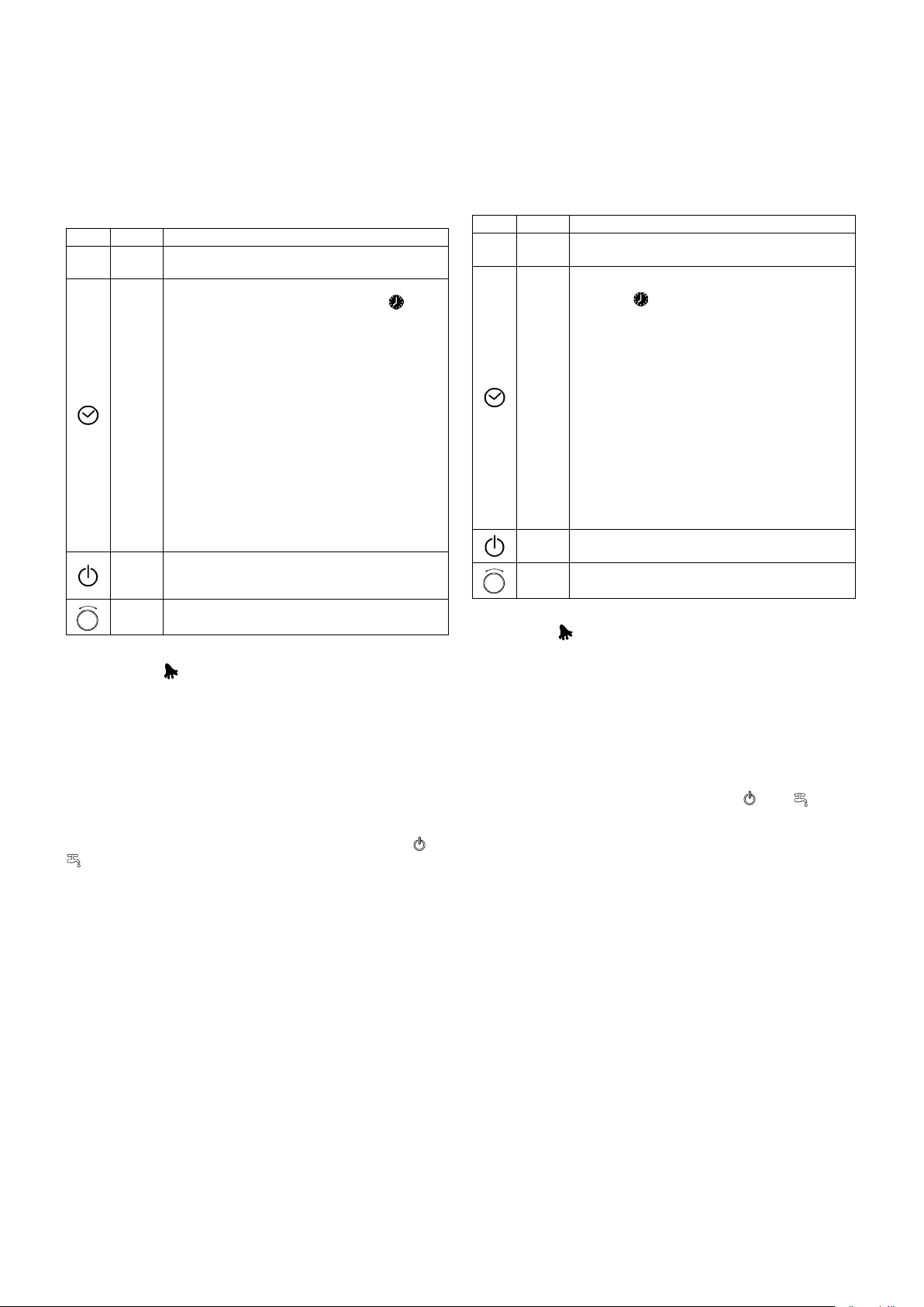
DESCRIPTION.
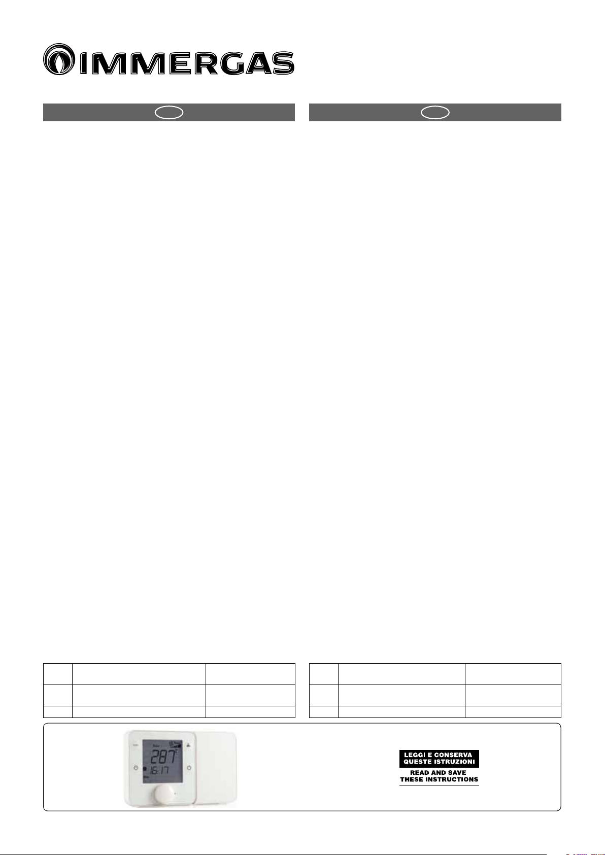
Zone remote control is the room terminal that, together with the programmable
controller, allows the user the control the temperature and humidity in residential
environments. Temperature and humidity setting is simple and intuitive, using
the knob on the front panel. Zone remote control also allows the user to make
some settings, such as the operating mode and time bands. e type of control
and displays depend exclusively on the controller that zone remote control is
connected to. e compact dimensions and elegant design make it suitable for
all types of rooms.
INSTALLATION WARNINGS.
Before performing any operations on the terminal, disconnect the power sup-
ply from the device by switching the main switch on the electrical panel OFF.
en remove the front part of the terminal from the rear to make the electrical
connections;
for the serial connection use three-wire shielded cable, AWG 20-22. e length
of the network must not exceed 500 m. For extended networks t a 120 Ohm
resistor between RX/TX+ and RX/TX- on the rst and last device, to avoid
possible communication problems.
TECHNICAL SPECIFICATIONS.
Power supply: 230 Vac (+10/-15%) 50/60 Hz
Maximum current: 2 VA
Operating conditions: -10T60 °C, 10 to 90% rH non-cond.
Storage conditions: -20T70 °C, 10 to 90% rH non-cond.
Environmental pollution: 2
PTI of insulating materials: PCB: from 175 to 249; insulation material: PTI 275
Soware class and structure: A
Index of protection of the case: IP20
Category of resistance to heat and re: D
Classication according to protection against electric shock: to be integrated
into class 1 or 2 appliances
Period of electrical stress across the insulating parts: long
Immunity against voltage surges: category II
Precision of temperature measurement: range 0T40 °C: ±1 °C;
over: ±1.5 °C
Precision of humidity measurement: range 0T60 °C, 20 to 80% rH: ±5% rH
PRODUCT SPECIFICATIONS.
In accordance with Regulation 811/2013 the temperature control device class is:
Class Contribution to the environmental
heating seasonal energy eciency Description
V +3% Zone remote control with-
out environment sensor
VI +4% Zone remote control
IT IE
AVVERTENZE GENERALI.
Tutti i prodotti Immergas sono protetti con idoneo imballaggio da trasporto. Il mate-
riale deve essere immagazzinato in ambienti asciutti ed al riparo dalle intemperie. Il
presente foglio istruzioni contiene informazioni tecniche relative all’installazione del
kit Immergas. Per quanto concerne le altre tematiche correlate all’installazione del kit
stesso (a titolo esemplicativo: sicurezza sui luoghi di lavoro, salvaguardia dell’ambiente,
prevenzioni degli infortuni), è necessario rispettare i dettami della normativa vigente
ed i principi della buona tecnica. L’installazione o il montaggio improprio dell’appa-
recchio e/o dei componenti, accessori, kit e dispositivi Immergas potrebbe dare luogo a
problematiche non prevedibili a priori nei confronti di persone, animali, cose. Leggere
attentamente le istruzioni a corredo del prodotto per una corretta installazione dello
stesso. L'installazione e la manutenzione devono essere eettuate in ottemperanza alle
normative vigenti, secondo le istruzioni del costruttore e da parte di personale abili-
tato nonché professionalmente qualicato, intendendo per tale quello avente specica
competenza tecnica nel settore degli impianti, come previsto dalla Legge.
DESCRIZIONE.
Il controllo remoto di zona è il terminale ambiente che, unito al gestore di
sistema, permette all’utente la regolazione della temperatura e dell’umidità di
un ambiente residenziale. L’impostazione di temperatura e umidità avviene in
maniera semplice e intuitiva grazie alla manopola frontale. Il controllo remoto
di zona fornisce inoltre all’utente la possibilità di modicare alcune imposta-
zioni dell’ambiente come la modalità di funzionamento e le fasce orarie. La
regolazione e le visualizzazioni dipendono esclusivamente dal controllo al quale
il controllo remoto di zona è connesso. L’ingombro limitato e il design elegante
inne consentono una facile adattabilità a tutti i tipi di ambienti.
AVVERTENZE PER L’INSTALLAZIONE
• Prima di eettuare qualsiasi operazione sul terminale, togliere l’alimentazione
dal dispositivo portando l’interruttore principale del quadro elettrico su OFF.
Rimuovere quindi la parte frontale del terminale e quindi quella posteriore
per eettuare i collegamenti elettrici;
• Per la connessione seriale utilizzare un cavo tripolare schermato, AWG 20-
22. La lunghezza della rete non deve superare i 500 m. Per reti molto estese
aggiungere una resistenza da 120 Ohm tra RX/TX+ e RX/TX- del primo e
dell’ultimo dispositivo per evitare possibili problemi di comunicazione.
CARATTERISTICHE TECNICHE.
Alimentazione: Modelli : 230 Vac (+10 …-15%) 50/60 Hz
Assorbimento massimo: 2 VA
Condizioni di funzionamento: -10T60 °C, 10…90% U.R. non cond.
Condizioni di immagazzinamento: -20T70 °C, 10…90% U.R. non cond.
Inquinamento ambientale: 2
PTI dei materiali di isolamento: PCB: da 175 a 249; materiale isolamento: PTI 275
Classe e struttura del soware: A
Grado di protezione dell’involucro: IP20
Categoria di resistenza al calore e al fuoco: D
Classicazione secondo protezione contro scosse elettriche: da integrare in
apparecchi di classe I o II
Periodo sollecitazioni elettriche delle parti isolanti: lungo
Immunità contro sovratensioni: categoria II
Precisione della misura di temperatura: range 0T40 °C: ±1 °C; oltre: ±1,5 °C
Precisione della misura di umidità: range 0T60 °C, 20...80% U.R.; ±5% U.R.
SCHEDA DI PRODOTTO.
In conformità al Regolamento 811/2013 la classe del dispositivo di controllo
della temperatura è:
Classe
Contributo all’ecienza energetica
stagionale di riscaldamento d’ambiente
Descrizione
V +3% Controllo remoto di zona
senza la sonda ambiente
VI +4% Controllo remoto di zona
Smontaggio
Dismantling

Smontaggio coperchio/ Cover dismantling
A1

A2
A3
Fig. 2
Fig. 1 Fig. 3
Fig. 6
Fig. 5
Fig. 4
E
131
83,5
86
Dimensioni elemento posteriore (mm) /
Dimensions of rear element (mm)
Dimensioni / Dimensions (mm)
Collegamenti elettrici / Electrical wiring
230 Vac
GND
Rx+/Tx+
Rx–/Tx–
N 230 V~
L 50/60 Hz
Fig. 8Fig. 7
Montaggio / Mounting
WALL
CONNECTIONS.
485 serial: AWG 20 to 22, shielded cable, Lmax=500 m
Power supply: Cross-section of the wires: 0.5 mm2to 1.5 mm2
ASSEMBLY.
1 separate the front from the rear of the terminal using a screwdriver (Fig. 2);
2 disconnect the 4-pin connector from the front part (Fig. 3);
3 to remove cover A1, unscrew screw A2 and press the point of attachment (Fig.
4); access terminal block A3 (Fig. 5)
4 drill the holes in the wall (dia. 5 mm); then insert the plugs and screws sup-
plied, making sure that the electrical wires pass through hole E (Fig. 6);
5 make the electrical connections (Fig. 7):
6 close cover A1, completing the same operations as described above in reverse;
7 plug the 4-pin connector back in (Fig. 8);
8 nally replace the terminal, starting with the bottom tabs and applying a hinge
movement. Make sure that the electrical wires are inside to ensure correct
fastening (click on).
DISMANTLING.
Insert a screwdriver into the clot at the top (Fig. 2) and press downwards to
detach the display.
GENERAL NOTES.
Avoid installing the boards in environments with the following characteristics:
relative humidity greater than the value specied;
• strong vibrations or knocks;
• exposure to water sprays;
• exposure to aggressive and polluting atmospheres(e.g.: sulphur and ammonia
fumes, saline mist, smoke) so as to avoid corrosion and/or oxidation;
• strong magnetic and/or radio frequency interference (for example, near
transmitting antennae);
• exposure to direct sunlight or the elements in general;
• large and rapid uctuations in the room temperature;
• environments where explosives or mixes of ammable gases are present;
• exposure to dust (formation of corrosive patina with possible oxidation and
reduction of insulation).
COLLEGAMENTI.
Seriale 485: AWG 20…22, cavo schermato, Lmax=500 m
Alimentazione: Sezione dei conduttori: 0,5 mm2…1,5 mm2
MONTAGGIO.
1 separare la parte anteriore da quella posteriore del terminale utilizzando un
cacciavite (g. 2);
2 scollegare il connettore a 4 poli dalla parte anteriore (g. 3);
3 per smontare il coperchio A1, svitare la vite A2 e premere in corrispondenza
del punto di aggancio (g.4); accedere alla morsettiera A3 (g. 5)
4 eseguire i fori a muro (Ø 5 mm); inserire quindi i tasselli e le viti a corredo,
avendo cura che i li elettrici escano dal foro E (g. 6);
5 eettuare i collegamenti elettrici (vedi g. 7).
6 chiudere il coperchio A1 eseguendo le operazioni in senso inverso rispetto a
quanto prima descritto;
7 reinserire il connettore a 4 poli (g. 8);
8 rimontare inne il terminale, partendo dai dentini inferiori con un movimento
a cerniera. Assicurarsi che i li elettrici entrino in sede, per avere il corretto
ssaggio a scatto.
SMONTAGGIO.
Inserire un cacciavite nella fessura superiore (g. 2) e premere verso il basso
per estrarre il display.
NOTE GENERALI.
Evitare l’installazione delle schede in ambienti che presentino le seguenti
caratteristiche:
• umidità relativa maggiore di quanto indicato;
• forti vibrazioni o urti;
• esposizione a getti d’acqua;
• esposizione ad atmosfere aggressive ed inquinanti (es.: gas solforici e ammo-
niacali, nebbie saline, fumi) con conseguente corrosione e/o ossidazione;
• elevate interferenze magnetiche e/o radiofrequenze (ad esempio vicino ad
antenne trasmittenti);
• esposizione all’irraggiamento solare diretto e agli agenti atmosferici in genere;
• ampie e rapide uttuazioni della temperatura ambiente;
• ambienti ove sono presenti esplosivi o miscele di gas inammabili;
• esposizione alla polvere (formazione di patina corrosiva con possibile ossi-
dazione e riduzione dell’isolamento).
TASTIERA.
Il signicato dei tasti e delle visualizzazioni può variare in funzione del controllo
a cui il controllo remoto di zona è collegato. Segue una descrizione delle im-
postazioni comuni. Se compare la scritta “CN” sul display signica che non c’è
comunicazione con il controllo elettronico al quale è connesso. All’accensione
del terminale è normale la visualizzazione di “CN” per circa 30s, no a quando
non si stabilisce la comunicazione. Nel caso poi nella parte bassa compaia la
scritta “Init” signica che il terminale è in fase di inizializzazione da parte del
controllo master. Una permanenza in questo stato superiore ai 10 minuti è
sintomo di problemi di comunicazione.
Tasto Descriz. Funzione
mode MODE Selezione modalità di funzionamento: premere nché
compare la modalità di funzionamento desiderata
CLOCK
Pressione breve: abilita/disabilita le fasce orarie. L’abili-
tazione corrisponde all’accensione dell’icona .
Pressione lunga (3 s): accesso al menu impostazione
orologio/fasce orarie. Selezionare tramite il selettore tra
le seguenti opzioni:
CLOCK: impostazione data/ora corrente: una volta
selezionata l’ora lampeggerà. Ruotare il selettore per
selezionare e premere per confermare;
TIMEBAND: impostazione fasce orarie. Per ogni fascia
oraria (max. 6) premere per impostare l’ora di inizio e il
relativo set point di temperatura. A anco comparirà l’i-
cona caratteristica in base allo stato giorno/notte e alla
presenza o meno dell’utente nell’abitazione. Selezionare
ESC per uscire dalla procedura e tornare alla visualizza-
zione standard.
ESC: per uscire
Dopo 10 s di attesa il controllo remoto di zona torna
automaticamente al menù principale.
POWER
Accensione/spegnimento della macchina. in alcuni
menù la pressione breve rappresenta l’equivalente
dell’opzione ESC.
-+
PUSH
Selettore
generale
Ruotare la manopola per impostare il valore e premere
per confermare
Accesso ai menù speciali: MODE + CLOCK per 3s per accedere al menù allarmi,
attivo solo se l’icona è accesa. Gli allarmi visualizzati dipendono dal controllo
elettronico al quale il controllo remoto di zona è collegato.
ABBINAMENTO A TRIO E GESTORE DI SISTEMA.
Per il funzionamento come gestione zona principale vedi il libretto di sistema.
ABBINAMENTO A MAGIS HERCULES PER LE ZONE 2 E 3.
Per il funzionamento come gestione zona principale vedi il libretto di caldaia.
PROGRAMMAZIONE PARAMETRI DI COMUNICAZIONE
CONTROLLO REMOTO DI ZONA.
Premendo e mantenendo premuti contemporaneamente i pulsanti “ ” e “
” è possibile entrare nel menù parametri di comunicazione, per accedere
è necessario inserire il codice d’accesso “22”. Per inserire il codice d’accesso
ruotare il selettore generale in senso orario no ad arrivare al codice d’accesso,
dopodiché premere il selettore generale per accedere al menù.
KEYPAD.
e meaning of the buttons and the displays may vary according to the controller
that zone remote control is connected to. Below is a description of the common
settings. If “CN” is shown on the display, it means there is no communication
with the electronic controller the terminal is connected to. On power-up, the ter-
minal normally shows “CN” for around 30s, until communication is established.
If “Init” is shown at the bottom, the terminal is being initialised by the master
controller. If this process lasts more than 10 minutes it means there are com-
munication problems.
Button Desc. Function
mode MODE Select operating mode: press until the desired operating
mode is displayed
CLOCK
Press briey: enable/disable the time bands. When
enabled the icon comes on.
Press and hold (3 s): access to the menu for setting the
clock/time bands. Use the main switch to select the
following options:
CLOCK: set current date/time: the time will start
ashing. Turn the main switch to select and press to
conrm;
TIMEBAND: time band setting. For each time band
(max. 6) press to set the starting time and the corre-
sponding temperature set point. e related icon will be
shown on the side, depending on the status (day/night)
and whether or not the home is occupied. Select ESC to
exit the procedure and return to the standard display.
ESC: to exit
Aer a 10 s timeout zone remote control automatically
returns to the main menu.
POWER Controlled device On/O; in some menus pressing the
button briey is the same as choosing ESC.
-+
PUSH
Main
switch
Turn the main switch to set the value and press to
conrm
Accessing the special menu: MODE + CLOCK for 3s to access the alarms menu,
active only if the icon is on. e alarms displayed depend on the electronic
controller that zone remote control is connected to.
COMBINATION TO TRIO AND SYSTEM CONTROLLER
About the function as a main zone refer to the system instruction manual.
COMBINATION TO MAGIS HERCULES FOR THE ZONES 2 - 3
About the function as a main zone refer to the boiler instruction manual.
PROGRAMMING THE REMOTE ZONE CONTROL PARAMETERS.
By simultaneously pressing and holding the buttons “ ” and “ ” one can
access the communication parameters programming menu; to access it one
must enter the access code “22”. To enter the access code turn the main selec-
tor clockwise until reaching the access code, then press the main selector to
access the menu.
Fig. 9
LEGENDA PANNELLO COMAN-
DI:
1 - Selettore generale
2 - Pulsante accensione / spegni-
mento
3 - Pulsante sanitario
4 - Pulsante selezione modalità
di funzionamento
5 - Pulsante fascia oraria
6 - Display
7 - Modalità di funzionamento
7A - Rarescamento / Sanita-
rio
7B - Inverno (Riscaldamento
/ Sanitario)
7C - Estate (Sanitario)
8 - Campo principale
9 - Fasce orarie attive
CONTROL PANEL KEY:
1 - Main switch
2 - On / o button
3 - Domestic hot water button
4 - Operating mode button
5 - Time slot button
6 - Display
7 - Operating mode
7A - Cooling mode (Cooling /
Domestic hot water)
7B - Winter mode (Heating /
Domestic hot water)
7C - Summer mode (Domes-
tic hot water)
8 - Main eld
9 - Active time slots
10 - Secondary eld
Parametri di comunicazione / Communication parameters
Menù Descrizione Description Range Default
Addr indirizzo /
Address
Permette di impostare l’indirizzo del con-
trollo remoto di zona
Allows to adjust the address of the remote
zone control
Magis Hercules
1 = zona principale / main zone
22 = zona 2 / zone 2
23 = zona 3 / zone 3
Trio
31 = Zona 1 / Zone 1
32 = Zona 2 / Zone 2
Gestore di sistema / Manager system
31 = Zona 1 / Zone 1
32 = Zona 2 / Zone 2
33 = Zona 3 / Zone 3
34 = Zona A.T. / H.T. zone
1
bAud velocità comunicazio-
ne / communication
speed
Permette di impostare la velocità di comu-
nicazione tra caldaia e comando remoto
di zona
Allows to set the communication speed
between the boiler and the remote zone
control
0 = 4800 bps
1 = 9600 bps Zona 1, 2, 3 e A.T.
Zone 1, 2, 3 and H.T.
2 = 19200 bps Zona 1 Magis Hercules
Magis Hercules Zone 1
1
bLbe Illuminazione display /
Display lighting
Permette di selezionare il modo di funziona-
mento del display Allows to set the display operation mode
0 =
1 =
2 =
0
bLIn Intensità illuminazione
/ Light intensity
Permette di stabilire l’intensità dell’illumi-
nazione Allows to set the light intensity 0 ÷ 5 4
PCaL Calibrazione sonda /
Probe calibration
Permette di calibrare la sonda di temperatu-
ra presente nel controllo remoto di zona
Allows to calibrate the temperature probe in
the remote zone control - 15 ÷ 15 K 0
CnSt Contrasto display /
Display contrast Permette di regolare il contrasto del display Allows to adjust the display contrast 0 ÷ 15 15
bu_d buzzer / Buzzer Permette di regolare il cicalino del controllo
remoto di zona
Allows to adjust the buzzer of the remote
zone control
0 = on
1 = o 0
PSu1 Pwd Password per modicare i parametri di
comunicazione interni (non modicare)
Password to change the internal communi-
cation parameters (do not change) 0 ÷ 999 22
P_In By-pass inizializza-
zione / Initialization
by-pass
Impostando il parametro ad un valore diver-
so da zero permette di evitare l’inizializza-
zione del controllo remoto di zona quando
viene alimentato (non modicare)
Setting the parameter with a value other
than zero allows to prevent the initializa-
tion of the remote zone control when it is
powered (do not change)
0 ÷ 1 1
year Anno / Ye a r Imposta l’anno Set the year 0 ÷ 99 0
Mont Mese / Month Imposta il mese Set the month 1 ÷ 12 1
mday Giorno / Day Imposta il giorno della settimana Set the day of the week 1 ÷ 31 1
uday Giorno - settimana /
Day - week Imposta il giorno della settimana Set the day of the week 1 ÷ 7 6
hour Ora / Time Imposta l’ora Set the hours 0 ÷ 23 0
mins Minuti / Minutes Imposta i minuti Set the minutes 0 ÷ 59 0
10 - Campo secondario
11 - Presenza anomalia in corso
12 - Richiesta riscaldamento /
rarescamento di una zona in
corso
13 - Funzionamento pompa di
calore in corso
14 - Funzionamento deumidica-
tore in corso
15 - Funzionamento bruciatore
caldaia in corso
16 - Antigelo in corso
17 - Giorno della settimana
18 - Fascia oraria corrente
19 - Umidità relativa
20 - Set point
21 - Funzione bloccata
22 - Unità di misura temperatura
11 - Anomaly in progress
12 - Heating / cooling request of a
zone in progress
13 - Heat pump operation in
progress
14 - Dehumidier operation in
progress
15 - Boiler burner operation in
progress
16 - Anti-freeze in progress
17 - Day of the week
18 - Current time slot
19 - Relative humidity
20 - Set point
21 - Function locked
22 - Temperature unit of measure-
ment

Other Immergas Remote Control manuals

Immergas Mini CRD User manual

Immergas

Immergas Mini CRD User manual

Immergas CARV2 Product manual

Immergas

Immergas CARV2 Product manual

Immergas System Manager Kit Product manual

Immergas

Immergas System Manager Kit Product manual

Immergas CRD User manual

Immergas

Immergas CRD User manual

Immergas SUPER CAR Product manual

Immergas

Immergas SUPER CAR Product manual

Immergas CARV2 Product manual

Immergas

Immergas CARV2 Product manual

Popular Remote Control manuals by other brands

Konftel CRC1 quick guide

Konftel

Konftel CRC1 quick guide

SmartDisk PowerPlay user guide

SmartDisk

SmartDisk PowerPlay user guide

Sony RM-V201 operating instructions

Sony

Sony RM-V201 operating instructions

Samsung MWR-WW10JN user manual

Samsung

Samsung MWR-WW10JN user manual

CopterX CX-CT6A instruction manual

CopterX

CopterX CX-CT6A instruction manual

Atlas WhisperTouch DWT-8 Series installation instructions

Atlas

Atlas WhisperTouch DWT-8 Series installation instructions

HeatTrak Wireless Two user guide

HeatTrak

HeatTrak Wireless Two user guide

Pinnacle PCTV quick start guide

Pinnacle

Pinnacle PCTV quick start guide

JMA M-BT Duplicating Procedures

JMA

JMA M-BT Duplicating Procedures

TANDBERG Remote Control quick guide

TANDBERG

TANDBERG Remote Control quick guide

Integral LED ILRC021 Guide

Integral LED

Integral LED ILRC021 Guide

RTI U2 Operation guide

RTI

RTI U2 Operation guide

Haier YR-HQ owner's manual

Haier

Haier YR-HQ owner's manual

Patriot Lighting 20704 quick start guide

Patriot Lighting

Patriot Lighting 20704 quick start guide

Contro l4 SR-250 Setup guide

Contro l4

Contro l4 SR-250 Setup guide

Hi-Tec Flash 7 Operation manual

Hi-Tec

Hi-Tec Flash 7 Operation manual

Fusion MS-ARX70 instructions

Fusion

Fusion MS-ARX70 instructions

X10 Europe UR86E user guide

X10 Europe

X10 Europe UR86E user guide

manuals.online logo
manuals.online logoBrands
  • About & Mission
  • Contact us
  • Privacy Policy
  • Terms and Conditions

Copyright 2025 Manuals.Online. All Rights Reserved.