Immergas CARV2 Product manual

CARV2
Wireless
Modulating remote
control
IE
Instructions and
warning book

2
Dear Client,
Our compliments for having chosen a top-quality
Immergas product, able to assure well-being and
safety for a long period of time.
As an Immergas customer you can also count on
a qualied aer-sales service, prepared and updated
to guarantee constant efficiency of your "Remote
Control".
We would like to supply you with some important
indications, the respect of which will conrm your
satisfaction with the Immergas product:
• Read the following pages carefully: you will
obtain useful suggestions regarding the correct use
of the appliance.
• For any interventions or routine maintenance
contact "Immergas Authorised Centres": they
have original spare parts and specic preparation.

3
INDEX
How to use the instruction book.................................................................4
Foreword ..................................................................................................4
General recommendations...........................................................................4
Case cleaning .................................................................................................5
1. Installation..............................................................................................6
1.1 Installation recommendations.................................................6
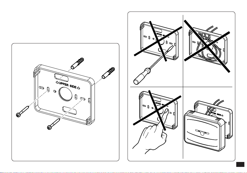
1.2 Installation operations..............................................................6
2. Description of Controls......................................................................11
2.1 Description of reception Base in radio frequency...............11
2.2 Base Signals. .............................................................................11
2.3 No communication between the Base and CARV2..............12
2.4 CARV2 description. ..................................................................13
3. Description of display.........................................................................14
3.1 Back-lighting............................................................................15
4. Start-up.................................................................................................16
4.1 Programming current day and time. ....................................16
4.2 Selection of functioning mode ..............................................16
5. Summer mode functions....................................................................19
5.1 DHW temperature setting......................................................19
5.2 DHW timer (for storage tank unit). .....................................19
6. Winter mode functions ......................................................................20
6.1 Manual functioning. ...............................................................20
6.2 Automatic functioning. ..........................................................21
6.3 Forced automatic functioning. ..............................................21
6.4 Boiler ow temperature..........................................................22
6.5 Room anti-freeze function.....................................................22
6.6 Functioning in winter mode with external temperature pro-
be. ..............................................................................................22
7. Cooling mode functions.....................................................................23
7.1 Manual functioning. ...............................................................23
7.2 Automatic functioning. ..........................................................24
7.3 Forced automatic functioning. ..............................................24
8. Information .........................................................................................25
9. Programming THE CARV2 .................................................................26
9.1 Setting comfort and economy room temperature...............26
9.2 Programming functioning time. ...........................................27
10. Diagnostics and errors........................................................................29
10.1 Diagnostics...............................................................................29
10.2 Reset errors...............................................................................29
10.3 Reset CARV2 remote control...................................................29
11. Special functions..................................................................................30
11.1 LANGUAGE (language selection). .......................................30
11.2 REGOLAZ (Management of regulation parameter). .........30
11.3 VACANZ (holiday program).................................................31
11.4 LEGION (anti-legionella function ). ....................................31
11.5 REMOTO (telephone control). .............................................31
11.6 CODE........................................................................................31
12. Functions protected by code (CODE)..............................................32
12.1 AMB (room probe - On / O or Modulating functioning
mode)........................................................................................32
12.2 RIDOTT (functioning in reduced mode)............................32
12.3 ANTIGL (anti-freeze level)....................................................33
12.4 ZONA (function not present on this model). .....................33
12.5 MANUTZ (programmed maintenance)..............................33
12.6
Association procedure in RF
....................................................33
12.7 RF disassociation procedure. .................................................33
12.8 Check the RF signal. ...............................................................34
13. CARV2 Base test procedure.................................................................34
14. Disabling the chrono-thermostat......................................................35
15. Replace the batteries ...........................................................................35
16. Technical characteristics.....................................................................36
16.1 Base CAR V2.............................................................................36
16.2 CAR
V2.......................................................................................36
16.3 Product specications.............................................................37
17. Factory setting .....................................................................................38
Page

4
HOW TO USE THE INSTRUCTION BOOK
e instruction book has been divided into 3 main parts:
in the rst, for the installer, the assembly and connection
phases of the remote control with the boiler are described;
in the second, all operating program customisation phases
are described;
in the third and last part, all operations for displaying and
keeping system operation under control are described.
FOREWORD
The “CAR V2 Wireless” (Comando Amico Remoto)
modulating remote control has been designed to guarantee
ideal temperature conditions at any time of the day and night
for each day of the week.
Only a few minutes are required for installation: the radio
frequency controlled Base is powered by the boiler and is
connected to the appliance with 2 cables, through which, it
receives and sends the adjustment and control commands
and receives the power supply. Whereas the chrono-
thermostat, with separate battery power supply, must only be
wall mounted and does not require any electrical connection
if not radio frequency acknowledgement with its own Base.
On completion of installation it is ready to function thanks
to the internal pre-set program. e customer can modify
the basic program according to requirements.
Programming the “CAR V2” is extremely easy and a wide
display allows constant control of all values set.
GENERAL RECOMMENDATIONS
is manual has been drawn-up for: the Installer and the
User.
• Carefully read the warnings contained in this document
as they are required to indicate the use of the CAR
V2 envisioned by the design hypothesis, the technical
features, the installation, assembly, programming,
adjustment and use instructions.
• e system must be in compliance with the IEC Standards
in force.
• e instruction manual must be considered part of the
CAR V2 and must be “kept for future reference”.
• Aer having removed the packaging, check the integrity
of the CAR V2. If in doubt, do not use it and contact the
Dealer or Manufacturer.
• e CAR V2 is intended only for the use for which it
has been expressly designed. Any other use must be
considered improper and therefore dangerous.
• Our products are produced in compliance with the Safety

5
Standards in force, it is therefore recommended to use all
devices or attentions in a way that injury/damage is not
caused to persons or objects.
• Do not remove parts of the CAR V2 when it is running.
• Do not use the CAR V2 exposed to heat sources or under
the scorching sun.
• Periodically check the battery charge.
• e manufacturer is relieved from any liability in the
following cases:
a) Incorrect installation.
b) Operating defects of the boiler to which the Remote
Control is applied.
c) Unauthorised modications or interventions.
d) Total or partial failure to comply with instructions.
e) Exceptional events etc.
CASE CLEANING
To clean the case of the CAR V2 use damp cloths. Never use
abrasive or powder detergents.
WARNING
Immergas reserves the right to make improvements and
modifications to details and accessories, excepting the
essential features of the model described and illustrated
herein.

6
1. INSTALLATION
1.1 Installation recommendations.
e CARV2, including the relative cables and connections
to the boiler, must be installed by specialised sta. On the
free initial check of the boiler, when the CARV2 is inserted
into the system, the Immergas authorised aer-sales centre
checks the connection to the generator terminal board
and adjusts functioning. e free check just of the CARV2
is not envisioned by the Immergas authorised aer-sales
centre is requested successively to the start phase of the
boiler warranty.
Important: installation of the CARV2 base wires are not
included in the free checks of the boiler and is to be carried
out by the installer company.
N.B.: follow the installation sequence by rst installing the
Base and then the CARV2.
1.2 Installation operations.
1) Separate the xing bottom from the lid of the CARV2
Base using a screwdriver as a lever in the relative recess
(Fig. 1-1). Pull the lid manually outwards to separate it
from the bottom.
2) Install the CARV2 Base bottom using the openings on
its rear part onto the wall or onto a recess box using the
relative supplied screws (Fig. 1-2).
1
3
2
Fig. 1-1

7
N.B.: it is recommended to use in non-critical electro-
magnetic places and in structures consisting of
material that is not mainly metal or shielding. During
installation, pay attention as indicated in Fig. 1-3.
Fig. 1-2 Fig. 1-3

8
Telephone control
(optional)
CHRONO RF
BASE RF
BOILER
3) To make the electrical connections (Fig. 1-4) do not
operate when the boiler is live. e connection must
be made to the relative clamps and the jumper on
clamps 40 and 41 of the boiler P.C.B. (if present) must
be eliminated.
en connect the base to the boiler clamps envisioned
during communication with the CARV2 or, if not
present, to the clamps envisioned for the CRD
indicated as 40 and 41 or 41 and 44.
Note: refer to the electrical connections stated in the
boiler instruction book.
Important: do not connect to clamps 42 and 43.
e connection to the boiler is made using two wires (Fig.
1-5) with a minimum section of 0.50 mm2and maximum
1.5 mm2and with a maximum length of 50 metres.
Fig. 1-4
Fig. 1-5

9
Fig. 1-7
Fig. 1-6
OK
1,5m
NO
N.B: for correct installation prepare a dedicated line for
the connection of the Base according to the Standards in
force regarding electrical systems. If this is not possible,
interference due to other electric cables could cause the
Base to malfunction.
4) Fasten the lid of the CARV2 Base to the support bottom,
engaging it using pressure (Fig. 1-5).
N.B.: when closing the lid, make sure it is aligned correctly
with the bottom.
6) Separate the xing template from the body of the CARV2
using a screwdriver as a lever in the relative recess (Fig.
1-8). Install the CARV2 away from heat sources and in a
suitable position to detect the room temperature correctly
(Fig. 1-6 and 1-7).
7) Install the CARV2 using the openings on its rear part
directly onto the wall or on a recess box using the relative
supplied screws.
8) Fasten the body of the CARV2 to the support template,
engaging it with pressure and using the two screws
supplied (Fig. 1-8).
9) Insert 2 1.5 V AA batteries (not supplied) into the pre-set
housing (Fig. 1-8) and close the battery compartment.
10) e Base and the CARV2 are associated to each other
during the testing phase in the factory. erefore, an
additional radio frequency association procedure is not
necessary.
1.5 m

10
1
2
33
4
5
Important: the xing screws (action n° 3) on rst
installation are not present on the CARV2, but are
supplied in a bag present in the packaging box.
Once the template is xed to the wall, x the body of
the CARV2 using the 2 screws.
Fig. 1-8

11
21 3
2. DESCRIPTION OF CONTROLS
2.1 Description of reception Base in radio frequency.
e radio frequency reception Base is a device, which allows
heating unit to be controlled by means of programs, settings
and modes determined by the associated CARV2.
2.2 Base Signals.
e two LEDs on the Base (1 and 3 Fig. 2-1) indicate the
operating status of the Base according to the table below.
State Le LED (1) Right LED (3)
No synchronisation 3 ash every
2 s o
Synchronisation
activated
(normal operation)
1 ash every
2 s
1 ash every
60 s
Association phase
0.5 s On,
0.5 s O
for 10 s
o
No communication
between the Base and
CARV2
3 ashes
every 2 s o
No communication
between the Base and
the boiler
2 ashes
every 2 s
1 ashes
every 60 s
Test
ashes
synchronised
with right
LED (5/s)
ashes
synchronised
with le
LED (5/s)
Forcing manually 3 ashes
every 2 s
3 ashes
every 2 s
Info search from
CARV2 o 1 ash
every 2 s
Key:
1 - Le LED
2 - TEST mode key
3 - Right LED
Fig. 2-1

12
2.3 No communication between the Base and CARV2.
If there is no communication between the CARV2 (flat
batteries), the boiler will be set to summer mode with the
DHW set to 50°C aer approx. 4-5 minutes. If necessary,
boiler operation can be forced in heating mode via the
Base. Proceed as follows in the event of no communication:
- press the button to access the test operation (Para. 13);
- keep the button pressed for 5 s within 30 s.
Both LEDs ash and the boiler works in heating mode with
a ow temperature in heating mode xed at 50 °C until
communication between the CAR V2 and the Base is restored.
Press the button once again to interrupt heating (2 Fig. 2-1).

13
2.4 CARV2 description.
Fig. 2-2
Ref. Description
1Main selector: O, Stand-by/anti-freeze,
Summer, Winter, Cooling
2
“Reset” boiler anomalies/“Esc” button to
exit parameter or return to previous menu
(programming mode)
3Comfort and economy room temperature
setting button
4Reset button to restart the CARV2 in the
event of an anomaly
5 Access button to adjust time, day and timer
6Access button to the programming/
parameter conrmation menu
7 Domestic hot water temperature selector
8 Heating temperature selector
9Information buttons
10 Manual and automatic mode button
11 Temperature decrease button
12 Temperature increase button

14
3. DESCRIPTION OF DISPLAY
Symbol Description
winter - DHW heating and
room central heating buttons are
enabled
summer - only the DHW central
heating function is enabled
Cooling - the cooling and DHW
central heating function is
enabled
request for room central heating
or cooling by CARV2
aqua celeris active/DHW
comfort in progress
request for DHW in progress
room central heating in progress
description of functioning of the
button (2 Fig. 2-2) - Reset, or esc
displays room temperature and
numerical data
external temperature display
Symbol Description
internal temperature display
function activation from remote
functioning with holiday timer
program
batteries at
description of functioning state
in use
anomaly in boiler presence
symbol
indicates that it is possible to
modify a parameter via the two
buttons (11 and 12 Fig. 2-2)
functioning with solar system
active

15
Symbol Description
functioning with external
temperature probe active
Indicates the association between
the Base and CARV2:
FLASHING: association in
progress.
FIXED: association completed
successfully.
If the signal is lost, the symbol
ashes simultaneously with the
fault signal (e.g. CARV2 out of
operating range of the base).
description of functioning of the
button (6 Fig. 2-2) - Menu or Ok
ame presence symbol (only
appears with the connection to
some boiler models)
symbols that identify the
functioning mode in the hourly
programming
Symbol Description
time bar that identies the
functioning period at “comfort”
and “economy” temperature
on the basis of the type of
programming (cooling, central
heating, DHW)
functioning with automatic
program.
functioning with manual
program
display of days of the week
N.B.: Some icons can assume dierent meanings according
to the context, see the successive paragraphs to identify the
functions activated by the presence of several icons at the
same time.
3.1 Back-lighting.
By pressing any button the display lightens for a set time.
N.B.: CARV2, standard model equipped with boiler does not
have backlighting function.

16
4.2 Selection of functioning mode
According to the functioning mode selected, the CARV2
performs the requests of the user, displaying the results
on the display.
By turning the main selector (ref. 1 Fig. 2-2) the following
functions can be selected: Stand-by/Anti-freeze, Summer,
Winter, Cooling.
Note: the room anti-freeze function is active in the following
modes: antifreeze, summer, winter.
• Off mode. The room anti-freeze function is not
guaranteed in this mode (the boiler anti-freeze function
remains active). e CARV2 is o but remains powered
and therefore the times and programs remain memorised.
4. STARTUP
4.1 Programming current day and time.
Switch the remote control on by turning the main selector
onto one of the functions available.
Press the button to enter time and current time
mode and press the button to modify the settings.
On entering the programming mode, the time starts to ash.
Modify the hour and minutes by pressing the + / - buttons
and the button to conrm. Select the day of the week
and conrm using the button.
Once regulation has been completed, press the button
to escape the regulation mode.
Fig. 4-1

17
Fig. 4-2
Fig. 4-3
• Stand-by/anti-freeze mode ( ). In this mode, the boiler
can only function in the event of anti-freeze request. In
this status the day, current time, any operating anomalies
and the room temperature are displayed anyway (Fig.
4-2).
• Summer mode ( ). In this mode the boiler is enabled
for producing domestic hot water excluding heating the
environment. e display shows the day and the current
time, the room temperature and hour bar with the daily
programming of the DHW timer together with the
relative symbols (Fig. 4-3).
• Winter mode ( ). In winter mode the boiler is enabled
for producing domestic hot water and for central
heating the environment. In winter, the CARV2 can work
in automatic or manual mode. For the description of
operation see chapter 6. e display shows the day and
current time, the room temperature and the hour bar with
the daily programming of the heating timer together with
the relative symbols (Fig.4-4).
Fig. 4-4

18
• Cooling mode ( ). In cooling mode the boiler is enabled
for the production of DHW and to control a chiller (only
for models set-up) for cooling rooms. In “cooling” mode,
the CARV2 can work in automatic or manual mode. For
the description of operation see chapter 7. e display
shows the day and current time, the room temperature
and the hour bar with the daily programming of the
cooling timer together with the relative symbols (Fig.
4-5). Fig. 4-5

19
5. SUMMER MODE FUNCTIONS
With the CARV2 in summer mode ( ), only the production
of DHW is enabled.
The boiler produces hot water according to the DHW
temperature set on the CARV2 .
5.1 DHW temperature setting.
Turn the selector ( ) to set the DHW temperature (see
Fig. 5-1).
By turning in a clockwise direction the temperature
increases and in an anti-clockwise direction it decreases.
e temperature is memorised aer the selector remains
still for a few seconds.
Fig. 5-1
5.2 DHW timer (for storage tank unit).
If the temperature of the DHW contained in the DHW
storage tank on two distinct levels (comfort and minimum)
is to be regulated, this is possible using the “PR SAN”
function. Regarding this, see the activation mode in the
chapter relative to programming.
The “comfort” temperature corresponds to the value
regulated on the DHW selector. e “minimum” temperature
corresponds to the minimum DHW value envisioned for the
boiler to which the CARV2 is coupled.
N.B.: if the CARV2 is functioning at minimum temperature
level it is possible to force the DHW temperature by acting
on the DHW selector.
e CARV2 is factory set with the DHW always activated on
“comfort” temperature (ON1 00.00 OFF1 24.00).
N.B.: the sanitary timer can also be used to set the time
bands of the device “Aqua celeris” and “recirculation
tank” if provided in in the boiler and depending on the
communication protocol used.

20
6. WINTER MODE FUNCTIONS
With the CARV2 in winter mode ( ), the production of
DHW and room central heating are enabled. Two main
functioning modes can be selected for room central
heating: automatic or manual. Plus a forced automatic
timed program.
- Manual ( ): the room temperature is kept constant
at the value set by the user every time, according to
requirements.
- Automatic ( ): the room temperature is regulated on
two levels (comfort and economy) during the day via a
program set by the user.
- Forced automatic ( ashing): the room temperature
is modified momentarily with respect to automatic
functioning until the successive passage between comfort
and energy mode of the automatic program set.
6.1 Manual functioning.
By pressing the button, pass alternately from
automatic to manual functioning.
Once manual mode is set, the icon lights up on the display
(Fig. 6-1).
Set the desired room temperature by simply pressing the
+ / - buttons and the room temperature setting will appear
on the display (Fig. 6-2). Just wait a few seconds to conrm
the new value.
In manual mode any room temperature from +10°C to
+35°C can be selected, which will be kept constant until
new adjustments are made or a dierent mode is selected.
Fig. 6-2
Fig. 6-1
Other manuals for CARV2
3
Table of contents
Other Immergas Remote Control manuals
Popular Remote Control manuals by other brands

Vetus
Vetus EC3 Operation manual and installation instructions

Mi-Light
Mi-Light FUT088 quick start guide

Fly-Dream
Fly-Dream V3 manual

LS Bedding Group
LS Bedding Group VFF/CDL-BF-11 operating instructions

Castle Creations
Castle Creations MAMBA XL X quick start guide

Modulus
Modulus RC-1 Preliminary user's manual