Immergas System Manager Kit Product manual

System
Manager Kit
Electronic control
Instructions and
warnings
Installer
User
Maintenance technician
IE


Dear Customer,
We wish to complement you for having chosen a top-quality Immergas product, that can assure
you long-term well-being and safety.
As an Immergas customer you can also count on Qualied Post-Sales Service, prepared and
updated to guarantee constant eciency of your "System Manager Kit".
We would like to provide you with some important indications, your observance of which will
ensure your satisfaction with the Immergas product:
• Read the following pages carefully: you will nd useful suggestions regarding the correct
use of the device.
• For assistance and scheduled maintenance, contact “Immergas Authorised Aer-Sales cen-
tres”: they have original spare parts and are specically trained.

4
INDEX PAGE
Foreword............................................................................................................................................................ 6
General recommendations................................................................................................................................ 6
Case cleaning..................................................................................................................................................... 6
Warning ............................................................................................................................................................. 6
1 Descriptions of Controls ......................................................................................................................... 7
1.1 Buttons description ..................................................................................................................................................7
1.2 Description of the display screen ........................................................................................................................... 8
1.3 Start-up ......................................................................................................................................................................9
1.3.1 Programming current time and day ...................................................................................................................... 9
1.4 Selection of functioning mode................................................................................................................................ 9
1.4.1 Functioning in stand-by mode ............................................................................................................................... 9
1.4.2 Operation in summer mode ................................................................................................................................... 9
1.4.3 Operation in summer mode with cooling...........................................................................................................10
1.4.4 Operation in winter mode.....................................................................................................................................10
1.4.5 Room antifreeze function......................................................................................................................................11
2 Programming the “system manager kit”............................................................................................... 12
2.1 Domestic hot water temperature setting.............................................................................................................12
2.2 Domestic hot water temperature setting on boiler side ....................................................................................13
2.3 Setting comfort and reduced room temperature................................................................................................13
2.4 User settings ............................................................................................................................................................14
2.5 Programming operating time in comfort mode.................................................................................................15
2.5.1 Daily hourly program ............................................................................................................................................15
2.5.2 Weekly hourly program.........................................................................................................................................16
2.5.3 Holiday program.....................................................................................................................................................16
3 Information ........................................................................................................................................... 18
4 Diagnostics and errors .......................................................................................................................... 20
4.1 Diagnostics.............................................................................................................................................................. 20
4.2 Reset errors.............................................................................................................................................................. 20
5 Assistance menu .................................................................................................................................... 21
5.1 Functions protected by code. ................................................................................................................................22
6 List of programmable parameters......................................................................................................... 34
7 Notes for zone devices ........................................................................................................................... 44
7.1 Notes for zone control............................................................................................................................................44
7.2 Notes for remote zone control ..............................................................................................................................44
7.3 Notes for remote zone panel .................................................................................................................................47
8 Notes for heat pumps board .................................................................................................................. 53
8.1 Notes for Magis pro................................................................................................................................................53
8.2 Notes for Magis Combo.........................................................................................................................................53
8.3 Notes for Audax Top 18/21 ErP............................................................................................................................ 53

5
INDEX PAGE
9 Wiring diagrams ................................................................................................................................... 55
9.1 System manager - power supply connection. .....................................................................................................55
9.2 System manager - connection to Audax Top 6/8/12/16 ErP.............................................................................55
9.3 System manager - connection to Audax Top 18/21 ErP. ...................................................................................56
9.4 System manager - connection to Magis Pro and Magis Combo. .....................................................................56
9.5 System manager - connection to boiler through TA input...............................................................................57
9.6 System manager - connection to Superior ErP boiler through external probe input. ..................................57
9.7 System manager - connection to Victrix TT boiler through external probe input. ......................................58
9.8 System manager - connection to Victrix Exa boiler through external probe input. .....................................58
9.9 System manager - expansions power supply connection..................................................................................59
9.10 System manager - expansion communication cable connection. ....................................................................60
9.11 System manager - TA request connection with 1 xed zone............................................................................61
9.12 System manager - connection to 1 sloping roof thermal solar system............................................................61
9.13 System manager - connection to 2 sloping roofs thermal solar system. .........................................................62
9.14 System manager - solar return probe connection..............................................................................................63
9.15 System manager - storage tank three-way connection......................................................................................63
9.16 System manager - connection to electric DHW integration resistance. .........................................................64
9.17 System manager - connection to electric central heating integration resistance...........................................64
9.18 System manager - puer probe connection........................................................................................................65
9.19 System manager - central heating/cooling three-way connection in systems with puer............................65
9.20 System manager - three-way integration connection in systems with puer.................................................66
9.21 System manager - expansion zone pump connection. ...................................................................................... 67
9.22 System manager - expansion zone ow probe connection...............................................................................67
9.23 System manager - expansion zone mixer connection. ......................................................................................68
9.24 System manager - connection to temperature and humidity probe................................................................68
9.25 System manager - connection to zone room thermostats.................................................................................69
9.26 System manager - connection to dehumidier kit.............................................................................................70
9.27 System manager - high-temperature zone valves connection..........................................................................71
9.28 System manager - summer/winter three-way connection................................................................................71
9.29 System manager - thermal discharge connection. .............................................................................................72
9.30 System manager - connection to DHW recirculation.......................................................................................72
9.31 System manager - Audax Top 6/8/12/16 ErP coil connection..........................................................................73
9.32 System manager - Audax Top 18/21 ErP coil connection.................................................................................74
9.33 System manager - connection to humidistat. .....................................................................................................75
9.34 System manager - connection to safety thermostat...........................................................................................75
9.35 System manager - connection to boiler alarm signal.........................................................................................76
9.36 System manager - connection to plate exchanger downstream of heat pump............................................... 76
9.37 System manager - connection to photovoltaic system. .....................................................................................77
9.38 System manager - connection to zone remote controls. ...................................................................................78
9.39 System manager - connection to zone remote panels. ......................................................................................79
9.40 System manager - connection to thermoue......................................................................................................79
9.41 System manager - connection to domotics with digital signals. ......................................................................80
9.42 System manager - connection to domotics with communication protocol....................................................81
9.43 System manager - connection to common ow probe......................................................................................81
10 List of anomalies.................................................................................................................................... 82

6
FOREWORD
e programmable “Immergas” “System Manager Kit”
was designed to guarantee ideal temperature conditions
at any time of day and night, for every single day of the
week, using the most economically advantageous source
of energy based on the characteristics of the installed
components and environmental conditions.
e control possibilities are:
1. Direct system without mixed valves and without
dehumidiers with integration either through resist-
ances or boilers, and management of the solar system
with a layer.
2. System for up to 3 zones, with 3-point mixer, and
management of a high temperature zone with boiler
integration.
3. System with 2 mixed zones with 3-point mixer
including the aforementioned characteristics and 1
xed.
4. As in the aforementioned cases but with the pos-
sibility of managing the solar part on two layers and
a high temperature zone.
5. As in the aforementioned cases but with the possibil-
ity of managing a puer for the solar integration of
CH.
e customer can change the basic program according
to their requirements.
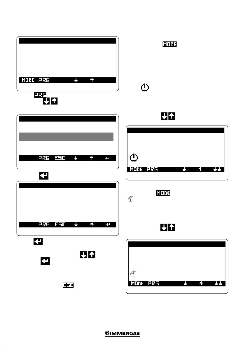
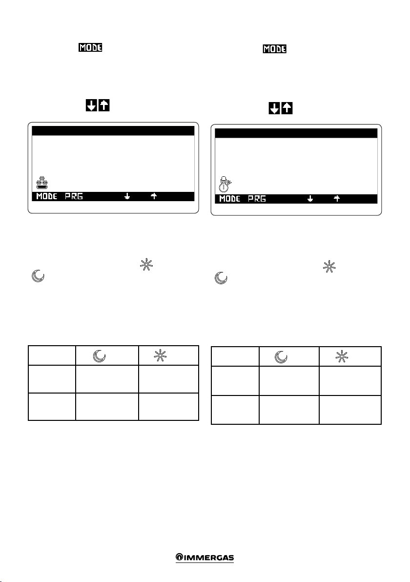
Programming the “System Manager Kit” is extremely
easy and a wide display screen allows you to constantly
control all set values.
GENERAL RECOMMENDATIONS
• Carefully read the warnings contained in this docu-
ment as they are required to indicate how to use the
“System Manager Kit” envisioned by the design, techni-
cal features, programming, adjustment and use.
• e system must be compliant with applicable IEC
Standards.
• e instruction manual must be considered a part of
the “System Manager Kit” and must be “kept for future
reference”.
• e “System Manager Kit” is intended only for the use
for which it has been expressly designed. Any other use
must be considered improper and therefore dangerous.
• Our products are produced in compliance with the
Safety Standards in force, it is therefore recommended
to use all devices or attentions in such a way that injury/
damage is not caused to persons or objects.
• Do not remove parts of the “System Manager Kit” when
it is operating.
• Do not use the “System Manager Kit” exposed to
sources of heat or under the scorching sun.
• In case the manager is switched-o, it is necessary to
also switch-o all devices connected to it (e.g. Heat
pump, expansions etc.).
• e manufacturer will not be held responsible in the
following cases:
a) Incorrect installation.
b) Malfunctions of the equipment to which the “System
manager kit” is applied.
c) Unauthorised changes or tampering.
d) Total or partial failure to comply with instructions.
e) Exceptional events etc.
N.B.: If an anomaly is detected on the external probe, the
system uses a xed temperature value of 6°C.
N.B.: All Room ermostat inputs, if they are not be-
ing used to request heating or cooling, can be used to
deactivate the zone of reference.
N.B.: When conguration is complete, restart the con-
trol zone by shutting o and turning the electric power
supply back on.
N.B.: Hook the heat pump up to the power supply only
once all necessary settings have been made.
CASE CLEANING
To clean the case of “System Manager Kit” use damp
cloths. Never use abrasive or powder detergents.
WARNING
Immergas reserves the right to make improvements and
changes to details and accessories, excepting the essential
features of the model described and illustrated herein.

7
Key:
1. Button to change the operating mode summer/
winter/stand-by ( ).
2. Access button to submenus ( ).
3. Button to move from a menu to the previous one
().
4. Downwards menu/values scroll button, decreasing
parameters button ( ).
5. Upwards menu/values scroll button, increasing
parameters ( ).
6. Button of confirmation for parameter variation
().
7. Viewing display.
N.B.: Some buttons can have dierent meanings and
functions depending on the displayed context.
1DESCRIPTIONS OF CONTROLS
1.1 BUTTONS DESCRIPTION
e button (1 Fig. 1-1) allows you to change the operating
mode of the system, specically:
• Summer (only DHW management).
• Sumer with cooling (summer air conditioning).
• Winter (winter air conditioning).
• Stand-by (no request for heating is passed onto the
generators and the solar system pump, except for the
room antifreeze protection that will be activated for
room temperature < 5°C).
Fig. 1-1
123456
7

8
1.2 DESCRIPTION OF THE DISPLAY SCREEN
winter - DHW heating and room central heating
functions are enabled;
summer - only the DHW heating function is
enabled;
comfort temperature is active;
operating with energy savings programme (re-
duced);
operating with automatic program;
operating with manual program;
operating with holiday timer program;
symbol indicating anomaly;
request for central heating in room in progress;
request for DHW in progress;
summer - DHW heating and room cooling func-
tions are enabled;
operating in “Party” mode;
request to heat or cool room;
solar panel operation in progress;
System in stand-by;
request for cooling in room in progress;
Dehumidier with neutral air
Dehumidier with cooled air
Post-circulation in progress
N.B.: some icons can assume dierent meanings ac-
cording to the context, see the following paragraphs to
identify the functions activated by the presence of several
icons at the same time.
e button (Ref. 2 Fig. 1-1) allows you to access the
submenus:
- Selection menu for room comfort and reduced Set
Point:
- Programming menu for clock and time periods (4 daily
on-o time periods for the comfort temperature);
- “Info” menu, to view the “System Manager Kit” input
data (ex. external temperature, ow temperature, set
ow temperature, DHW temperature, solar storage
tank probe temperature);
- Alarms records;
- Assistance menu.
e button (Ref. 3 Fig. 1-1) allows you to move back from
a current menu to the previous one.
e buttons (Ref. 4 and 5 Fig. 1-1) are used to cyclically
scroll through the menus on the display. On the main
screen they allow you to view:
- "Set DHW";
- “Set room and ow zone 1”;
- “Set room and ow zone 2”;
- “Set room and ow zone 3”;
- “Set room and ow zone AT”;
While the “DHW Set”, “Room Set”, “Flow Set” are dis-
played, press the button (Ref. 6 Fig. 1-1) to access and
edit the displayed data; when the “Room Set” is changed
the device will switch to manual operation until the
controlled status change of the rst time range in the
“automatic” condition. When a variation is made to “Set
sanitario” (Set DHW) or “Set mandata” (Set ow) only
the relative values will be changed; a variation made to
“Set mandata” (Set ow), if an external probe is being
used, will be read by the supervisor as an oset compared
to the value determined by the set curve. e set ow
being sent to the heat pump and/or integration boiler
will have a value of the maximum set value of ± 15°C.
If anomalies arise, from the heat pump, the current
anomaly will appear on the screen and the possibility
of verifying it in the alarms records menu. Within this
menu it is possible to reset the alarms records or send
the reset command to the machine (see Paragraph 4.2),
it is possible to send a maximum of 3 consecutive restore
commands; at the end of the three tries a new restore
request will be provided aer one hour.

9
1.3 STARTUP
1.3.1 Programming current time and day
Fig. 1-2
08:50 VE 10/06/11 M01
Sitting room
T: 00.0 °C
U: 00.0 %
Press the button to enter the navigation menu.
Press buttons until selecting menu “02. TIME
SLOTS
Fig. 1-3
Navigation menu
02. SET-POINT
03. Time slots
04. Info
Press button to enter current “Time and Day” mode.
Clock K01
Setting the clock:
09:50
Friday 10/06/11
Fig. 1-4
Press the button again to make the value indicating
the hours to ash.
Set as desired by pressing arrows . At the end,
press button to conrm and for the minute gure
to start blinking.
Proceed in the same way adjusting the minutes, day of
the week, day, month and year.
At the end press button twice to go back to the
main screen.
1.4 SELECTION OF FUNCTIONING MODE
e “System Manager Kit” according to the functioning
mode selected, the CAR V2 remote control performs the
requests of the user, displaying the results on the display.
By pressing button the status changes sequen-
tially from stand-by to summer operation, summer with
cooling, winter and party.
e antifreeze function is also provided in the mode:
stand-by, summer and winter.
1.4.1 Functioning in stand-by mode
With the “System Manager Kit” in stand-by mode, the
symbol is displayed (see Fig. 1-5). e system can
only work in case of room antifreeze request. In this
status the current day and time are still displayed, along
with any operating faults, present humidity percentage
and ambient temperature in the main area.
Note: press arrows to view the same parameters
for any other stored areas.
1.4.2 Operation in summer mode
Pressing button switches to summer operation
() the “System Manager Kit” enables the system to
domestic hot water production only, disabling room
central heating (see Fig. 1-6). e display shows current
day and time, any operating faults, ambient temperature
and humidity percentage in the main area.
N.B.: press arrows to view the same parameters
for any other stored areas.
Fig. 1-5
08:50 VE 10/06/11 M01
Sitting room
T: 00.0 °C
U: 00.0 %
Fig. 1-6
08:50 VE 10/06/11 M01
Sitting room
T: 00.0 °C
U: 00.0 %

10
1.4.3 Operation in summer mode with cooling
Pressing button switches to summer operation
with cooling: the “System Manager Kit” enables both
domestic hot water production and room cooling (see
Fig. 1-7). e display shows current day and time, any
operating faults, ambient temperature and humidity
percentage in the main area.
N.B.: press arrows to view the same parameters
for any other stored areas.
e “System Manager Kit” allows automatic functioning
in cooling mode, in which a time program manages the
room temperature during the hours of the day.
e desired room temperature can be adjusted onto
two independent levels: comfort ( ) and reduced
(). e distribution of these levels throughout the
day or week is controlled by the hourly programming
(see Paragraph 2.3).
e “System Manager Kit” is factory set as shown in
the table below. If this should not satisfy requirements,
it is possible to modify it as described in the following
chapters.
Days 28°C 25°C
Mon-Fri - 0 ÷ 24
Sat-Sun - 0 ÷ 24
N.B.: the system is designed to function on comfort
and reduced temperature levels depending on the hour
program set. erefore also during functioning in re-
duced room temperature conditions, if the temperature
measured is above that set, the system can switch-on.
1.4.4 Operation in winter mode
Pressing button switches to winter operation:
the “System Manager Kit” enables both domestic hot
water production and room central heating (see Fig. 1-8).
e display shows current day and time, any operating
faults, ambient temperature and humidity percentage
in the main area.
N.B.: press arrows to view the same parameters
for any other stored areas.
e “System Manager Kit” allows automatic functioning
in central heating mode, in which a time program man-
ages the room temperature during the hours of the day.
e desired room temperature can be adjusted onto
two independent levels: comfort ( ) and reduced
(). e distribution of these levels throughout the
day or week is controlled by the hourly programming
(see Paragraph 2.3).
e “System Manager Kit” is factory set as shown in
the table below. If this should not satisfy requirements,
it is possible to modify it as described in the following
chapters.
Days 16°C 20°C
Mon-Fri - 0 ÷ 24
Sat-Sun - 0 ÷ 24
N.B.: the system is designed to function on comfort
and reduced temperature levels depending on the hour
program set. erefore also during functioning in re-
duced temperature conditions, if the room temperature
measured is below that set, the system can switch-on.
08:50 VE 10/06/11 M01
Sitting room
T: 00.0 °C
U: 00.0 %
Fig. 1-7
08:50 VE 10/06/11 M01
Sitting room
T: 00.0 °C
U: 00.0 %
Fig. 1-8

11
1.4.5 Room antifreeze function
Note: this function is only active in the winter, stand-by
and summer mode.
e antifreeze function has maximum priority with
respect to other settings. When ambient temperature
drops below 5°C a central heating request at minimum
setting is made. is situation remains active until there
is a variation in room temperature of 1°C equal to 6°C
measured in the area where the temperature below 5
°C is detected.

12
2PROGRAMMING THE
“SYSTEM MANAGER KIT”
Programming of the “System Manager Kit” allows to set/
modify the following parameters:
- DHW temperature setting;
- comfort and low temperature levels;
- operating daily / weekly hourly program/ holiday
program.
- assistance menu.
2.1 DOMESTIC HOT WATER TEMPERATURE
SETTING
From the main screen, press arrows until the
DHW set is displayed (Fig. 2-1 and 2-2).
08:50 VE 10/06/11 M02
DHW
DHW time slots: No
Manual set
(permanent): 00 °C
D.H.W.T. : 00.0 °C
Fig. 2-1
Press the button again to make the rst reading
(dhw time slots) blink.
Set as desired by pressing arrows . At the end,
press button to conrm and for the next value
(Manual Set) to start blinking. Proceed in the same way
to set the next gures.
Aer setting the last gure, when button is pressed
the cursor no longer blinks and it is possible to change
screens with buttons .
At the end press button twice to go back to the
main screen.
• Set manual: it lets you set the DHW set-point valid
until the next time range change;
• water T.: it displays in real time the domestic hot water
temperature.
• Dhw time slots: enables only the Manual Set to be
congured. If “Yes”, Set Comfort and Set Eco can also
be congured.
08:50 VE 10/06/11 M03
DHW
(Hou..clips dis.)
Set COMFORT: 00 °C
Set ECO : 00 °C
D.H.W.T. : 00.0 °C
Fig. 2-2
Press the button again to make the rst reading
(Set Comfort) blink.
Set as desired by pressing arrows . At the end,
press button to conrm and for the next gure
(Set ECO) to start blinking. Proceed in the same way to
set the next gures.
Aer setting the last gure, when button is pressed
the cursor no longer blinks and it is possible to change
screens with buttons .
At the end press button twice to go back to the
main screen.
• Set COMFORT:it lets you set the DHW set-point in
the COMFORT time range (refer to settings of DHW
time slots);
• Set ECO: it lets you set the DHW set-point in the ECO
time range (refer to settings of DHW time slots);
• water T.: it displays in real time the domestic hot water
temperature.

13
2.2 DOMESTIC HOT WATER TEMPERATURE
SETTING ON BOILER SIDE
From the main screen, press arrows until the
boiler side domestic hot water temperature gure is
displayed (Fig. 2-3).
08:50 VE 10/06/11 M04
DHW
Boiler set: 00.0
Boiler temp: 00.0
Fig. 2-3
Press the button again to make the rst reading
(boiler side water T.) blink.
Set as desired by pressing arrows . At the end,
press button to conrm and for the next gure (Set
boiler) to start blinking.
Aer setting the last gure, when button is pressed
the cursor no longer blinks and it is possible to change
screens with buttons .
N.B.: these settings are only visible in case the boiler is
connected to the system manager through “MODBUS”.
At the end press button twice to go back to the
main screen.
2.3 SETTING COMFORT AND REDUCED
ROOM TEMPERATURE
Press the button to enter the navigation menu.
Press buttons until selecting menu “01. SET
POINT”.
Fig. 2-4
Navigation menu
06. SERVICE
01. SET-POINT
02. USER SETTING
Press button to enter the rst room set (Summer).
Set room S02
SUMMER WITH FREEZ- ZN 2
Comfort: 25.0 °C
Reduced: 28.0 °C
Humidity: 50.0 %
Fig. 2-5
Press the button again to make the first value
(Comfort) to ash.
Set as desired by pressing arrows . At the end,
press button to conrm and for the next gure
(Low) to start blinking. Proceed in the same way for this
setting then go to the last setting (Humidity).
When button is pressed the cursor no longer blinks
and it is possible to change screen with buttons
and set the gures of the next room sets (Summer with
cooling, Winter) for each congured area.
Default settings are 25°/20° (summer/winter comfort T.)
and 28°/16° (summer/winter low T.) and 50% (humidity).
e limits for ambient temperature will be from 5° to 35°
and for relative humidity from 30% to 60%.
Note: the new settings will be used at the next time
range variation or temporarily setting the system to
stand-by mode.
At the end press button twice to go back to the
main screen.

14
2.4 USER SETTINGS
Press the button to enter the navigation menu.
Press buttons until selecting menu “02. SET.
USER”.
Fig. 2-6
Navigation menu
01. SET-POINT
02. USER SETTING
03. TIME PROGRAMS
Press the button to enter the menu.
- Party mode. Activating the party mode sets all zones
in “Comfort” mode until the next programmed status
change. e central heating or cooling mode will de-
pend on the system state.
User setting D01
Party mode: No
Fig. 2-7
User setting D02
Gas prices
Gas type: Methane
Methane: 000.00 c€/m3
LPG: 000.00 c€/m3
Fig. 2-8
- Gas prices. It lets you enter gas prices, also selecting
GAS type (methane/LPG). ese data allow the sys-
tem manager to calculate the working point with the
maximum eciency between heat pump operation and
GAS boiler.
User setting D03
Electric energy prices
Elet.F1: 000.00 c€/kWh
Elet.F2: 000.00 c€/kWh
Elet.F3: 000.00 c€/kWh
Fig. 2-9
- Electricity prices. It lets you enter electricity prices.
User setting D04
Energy band time
Tariff: Two part
F1: 00:00 - 00:00
F2: 00:00 - 00:00
Fig. 2-10
- Time slots. Allows selecting between Dual-rate and
Multi-rate tari, enter the time slots related to the
electricity prices.
- Dual. You can set the two daily time slots, the F1 and
F2 taris are valid from Monday to Friday while the
F2 tari is applied to Saturday and Sunday.
- Multi-rate. You can set the three daily time slots, the
F1, F2 and F3 taris are valid from Monday to Friday
while the F2 tari is applied to Saturday and Sunday.
- Heat pump manual disabling. e option lets you
permanently disable heat pumps as the main generator.
Heat pump temporary enabling. e option lets you
enable heat pumps according to the time slots.
User setting D05
Heat pump manual
disable comand: No
Heat pump tempor.
enable comand: No
Fig. 2-11
Press button for the option “Disable heat pumps”
to start blinking.

15
Press arrows to confirm (YES) or cancel
(NO) any option. Press the button to validate
the modication.
At the end press button twice to go back to the
main screen.
User set. D06
Calendar enable HP
Mon : CAL1 | Tue : CAL1
Wed : CAL1 | Thur : CAL1
Fri : CAL1 | Sat : CAL1
Sun : CAL1 |
Fig. 2-12
In case of heat pump temporary enable you can set the
ignitions calendar.
User set. D07
Integration manual
disable comand: No
Fig. 2-13
- Integration manual disabling. Enables the operation
of the secondary generator to be permanently disabled.
- Separate management of central heating/cooling.
e option enables a diverter valve to be activated for
separation of hot/cold circuits. In the event of forced
activation of the cooling request, the generator is acti-
vated at the set temperature.
User set. D08
Separate management
heating/cooling
Cooling set:
00.0 °C
Fig. 2-14
Press button for the option “Separate heat./cool.
management” to start blinking.
Set as desired by pressing arrows . Press the
button to validate the modication.
At the end press button twice to go back to the
main screen.
- “Fancoil” in winter. e option exclusively allows fan
coils to be used in winter operation mode. is option
may only be selected if it is provided for in the system
denition. Fancoils operate at the temperature set on
this page.
User setting D09
Fancoil in winter: No
00.0
Fig. 2-15
Press button for the option “Fancoil in winter”
to start blinking.
Press arrows to confirm (YES) or cancel
(NO) any option. Press the button to validate
the modication.
At the end press button twice to go back to the
main screen.
2.5 PROGRAMMING OPERATING TIME IN
COMFORT MODE
By following the points described below, it is possible to
create or modify the time program.
2.5.1 Daily hourly program
Press the button to enter the navigation menu.
Press buttons until selecting menu “02. TIME
S L O T S ”.
Fig. 2-16
Navigation menu
02. USER SETTING
03. Time PROGRAMS
04. Info
• Time slots. It is possible to set 4 calendars containing
4 time slots for system operation in comfort mode.
During the time outside these 4 time slots, the system
will work in economy mode.
Aer setting these 4 calendars it is possible to associate
them to the various days of the week and DHW func-
tion according to one's needs.

16
Press the button to enter the menu.
Press buttons to access screen “Comfort T.
Ranges”.
T.comfort clips K02
CALENDAR 1
F1: 00:00 - 00:00
F2: 00:00 - 00:00
F3: 00:00 - 00:00
F4: 00:00 - 00:00
Fig. 2-17
Press button for the time of the rst of the 4 time
ranges to start blinking, with which it is possible to
dene the system's switch on and o time to maintain
Comfort temperature.
Press arrows to change the time. Press button
to conrm the change and move to the next time
range.
Proceed in the same way to set the next time slots.
N.B.: the clips can be changed with a minimum time
of 15 minutes.
In the event of not using all 4 time slots, set the unused
ones with switch on and o time set to “00:00”.
Proceed in the same way to program all days of the week.
In the event programming should be repeated it may be
copied from an already programmed day following the
instructions in Paragraph “2.5.2 Weekly hourly program”.
2.5.2 Weekly hourly program
Press the button to enter the navigation menu.
Press buttons until selecting menu “03. TIME
SLOTS” (Fig. 2-6).
Press the button to enter the menu.
Scroll through screens with buttons until access-
ing the menu “Program for zone 1.” (Fig. 2-18).
Time slots (Calendars from 1 to 4) are assigned to Zones
and DHW in these menus.
erefore each day may be personalised with 4 dierent
operating programs.
For convenient selection, the bottom part displays the
graphics of the relevant calendar being selected (Fig.
2-18).
Fig. 2-18
T.comfort clips K06
Z1:
Mon: CAL1 |Tue: CAL1
Wed: CAL1 |Thu: CAL1
Fri: CAL1 |Sat: CAL1
Sun: CAL1
Press button for the calendar to be assigned to
Monday to start blinking. Press arrows to set
the desired calendar for zone 1 on Monday. Press button
to conrm and go to the next day.
Proceed in the same way to set calendars of individual
days of the week for individual zones and /or DHW.
At the end press button twice to go back to the
main screen.
2.5.3 Holiday program
Press the button to enter the navigation menu.
Press buttons until selecting menu “03. TIME
SLOTS” (Fig. 2-16).
Press the button to enter the menu.
Scroll through screens with buttons until access-
ing the menu “Time slots”.
Time slotsK11
Holiday period:
30/06/11 - 30/06/11
Enable holiday: No
Fig. 2-19
Press button for the gure indicating the start date
of the holiday to start blinking.
Press arrows to set day/month/year.

17
Proceed in the same way to set the end date of the holiday.
e start and end date (restart will take place on the end
date) will disable DHW and central heating/cooling op-
eration; central heating is set at 5°C (all zones) to control
ambient antifreeze. All operating modes for controlling
the solar heating system will remain active, if activated
in the conguration menu.
At the end press button twice to go back to the
main screen.
Holiday function activation is indicated by the icon
switching on in the main screen (Fig. 2-20).
Fig. 2-20
08:50 VE 10/06/11 M01
Sitting room
T: 00.0 °C
U: 00.0 %

18
3INFORMATION
Press the button to access the programming menu.
Press buttons until selecting menu “04. INFO”
(Fig. 3-1).
Navigation menu
Fig. 3-1
03. TIME PROGRAMS
04. INFO
05. ALARMS HISTORY
Press the button to enter the menu.
Within the menu, using the arrows, one can view
the data of interest for the user.
- Heat pump probes temperature
Info I01
Plant temperature
General ow: 00.0 °C
00.0
External: 00.0 °C
Fig. 3-2
- Temperature required for area systems.
e presence of a request from a zone is highlighted
with an asterisk.
Info I02
FLOW SET-POINT
System: 12.5°C
Zone 01: 12.5°C
Zone 02: 14.1°C
Fig. 3-3
- Dew point
Info I03
DEW POINT
Zone 01: 00.0 °C
Fig. 3-4
- DHW temperature
Info I04
DHW Probe Temperature
DHW T.: 00.0 °C
Set-point: 00.0 °C
Antileg.: OFF
Fig. 3-5
- Area probes temperature (I05 ÷I08)
In the event of active requests for dehumidication
with neutral air or dehumidication with cooled air
the relative icons will be displayed.
Info I05
ZN1 Probe temperature
Sitting room
Flow t.: 21.5°C
Room t.: 25.2°C
Room H.: 044.0 °C
Fig. 3-6
- Solar probes temperature
Info I09
Probes temperature
Solar
Tank temp.: 025.0 °C
Collec. 1 T.: 024.8 °C
Fig. 3-7

19
- Puer temperature
Info I10
Puffer temperature
Puffer set: 00.0 °C
Puffer temp.: 00.0 °C
Plant circ.: NO
Pre-heating: NO
Fig. 3-8
- Additional functions probes temperature
Info I11
Probes temperature
Hot boiler: 00.0 °C
Cold source: 00.0 °C
Return t.: 000.0 °C
Fig. 3-9
- Audax data 1 ÷4
Info I12
Inverter
Flow t.: 24°C
Return t.: 24°C
Mode: Cooling
Frequency: 00.0 Hz
Fig. 3-10
- Machine eciency
Info I16
COP calculation
Minimum: 02.00
Active: 02.93
Fig. 3-11
- Machine eciency
Info I16
COP calculation
Minimum: 02.00
Audax 1: 02.93
1: 3.52 2: 2.97
3: 4.01 4: 2.98
Fig. 3-12
- Tonnes of CO2saved by using the heat pump
Info I17
CO2 saving
Tonnes of CO2
saved: 00000 t
Fig. 3-13
- Integration data
Info I18
Integration
Storage tank unit : ON
Set-point : 00.0 °C
Plant res. : OFF
Sanitary res. : OFF
Fig. 3-14
- Sundry inputs
Info I19
Other input
Generators: NO
Photovoltaic: OFF
Fig. 3-15

20
4DIAGNOSTICS
AND ERRORS
4.1 DIAGNOSTICS.
e “System Manager Kit” control continually controls
the functioning status of the whole system and signals
any anomalies, stating the corresponding error code on
the display.
In the case of a fault that cannot be reset, contact a quali-
ed technician (e.g. the Immergas Aer-Sales Technical
Assistance Service).
e alarm code is displayed in the event of an error (e.g.
A0036, Fig. 4-1), with the symbol and icon
above the relevant button.
Fig. 4-1
08:50 VE 10/06/11 M01
Sitting room
T: 00.0 °C
U: 00.0 % A0036
Press the button to display the “Alarms log”; this
section displays occurred alarms, not yet reset, from the
most recent to the oldest.
Press arrows to scroll and display all extant
alarms.
Alarms log H01
N° 04 09:50 10/06/11
A0036
Alarm off-line
Audax
Fig. 4-2
e following faults are managed by the “System Man-
ager Kit”:
- Storage tank probes fault (upper, lower and for central
heating)
- Solar collector probe anomalies
- Flow zone probe faults
- Return probe fault (solar)
- Heat pump anomalies
- Boiler anomaly
- Disabled solar operation
- Dehumidier fault
- Ambient and humidity probe fault (for all zones)
If no alarm has been triggered, it is still possible to view
the “Alarms log” by proceeding as follows:
- press the button ;
- scroll with buttons the navigation menu and
select “05. ALARMS RECORDS”.
Navigation menu
04. INFO
05. ALARMS HISTORY
06. SERVICE
Fig. 4-3
- Press the button to enter the menu.
As well as the error codes referring to the functioning
state of the system, the“System Manager Kit” also checks
its own functioning state, indicating any malfunctions.
4.2 RESET ERRORS
Press the button to display the “Alarms log” or via
the navigation menu (Fig. 4-3).
Press and hold the RES button (Fig. 4-2) to display the
screen where it will be possible to reset the alarms and
heat pump log (Fig. 4-4).
Alarms log H02
Reset log? No
Reset alarm of
Audax and boiler: No
Fig. 4-4
Press button for the option “Reset log” to start
blinking.
Press arrows to conrm (YES) or cancel (NO)
any reset. At the end, press button to conrm and
for the option “Reset Audax and boiler alarms” to start
blinking. Proceed in the same manner to reset any pump
and boiler alarms.
At the end press button twice to go back to the
main screen.
Other manuals for System Manager Kit
1
Table of contents
Other Immergas Remote Control manuals
Popular Remote Control manuals by other brands

Silvercrest
Silvercrest 10-in-1 Remote Control operating manual

One Forall
One Forall URC-7140 instruction manual

Telesystem
Telesystem All in One 58040107 quick guide

Silent Gliss
Silent Gliss SG 11429 Installation and user manual

T'nB
T'nB BIG EASY User instructions

Contec
Contec SRC-350 Programming and operating instructions