Immergas VICTRIX PRO V2 User manual

IT IE
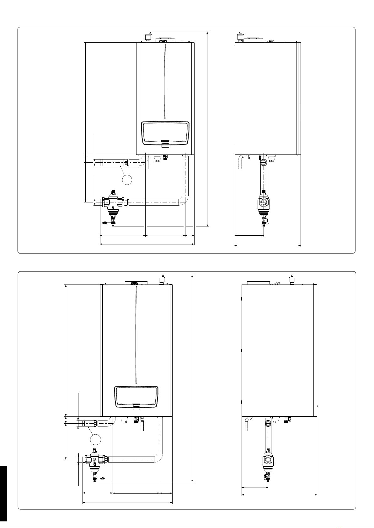
KIT DEFANGATORE VICTRIX PRO V2
INSTALLAZIONE SINGOLA COD. 3.033673
VICTRIX PRO V2 DIRT SEPARATOR KIT
SINGLE INSTALLATION COD. 3.033673
Avvertenze generali
Tutti i prodotti Immergas sono protetti con idoneo imballaggio da
trasporto.
Il materiale deve essere immagazzinato in ambienti asciutti ed al
riparo dalle intemperie.
Il presente foglio istruzioni contiene informazioni tecniche relative
all’installazione del kit Immergas. Per quanto concerne le altre
tematiche correlate all’installazione del kit stesso (a titolo esempli-
cativo: sicurezza sui luoghi di lavoro, salvaguardia dell’ambiente,
prevenzioni degli infortuni), è necessario rispettare i dettami della
normativa vigente ed i principi della buona tecnica.
L’installazione o il montaggio improprio dell’apparecchio e/o dei
componenti, accessori, kit e dispositivi Immergas potrebbe dare luogo
a problematiche non prevedibili a priori nei confronti di persone,
animali, cose. Leggere attentamente le istruzioni a corredo del pro-
dotto per una corretta installazione dello stesso.
L'installazione e la manutenzione devono essere eettuate in ottem-
peranza alle normative vigenti, secondo le istruzioni del costruttore e
da parte di personale abilitato nonché professionalmente qualicato,
intendendo per tale quello avente specica competenza tecnica nel
settore degli impianti, come previsto dalla Legge.
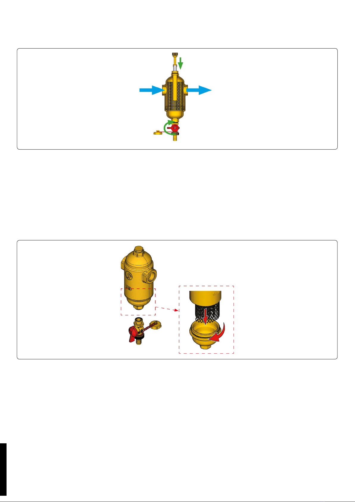
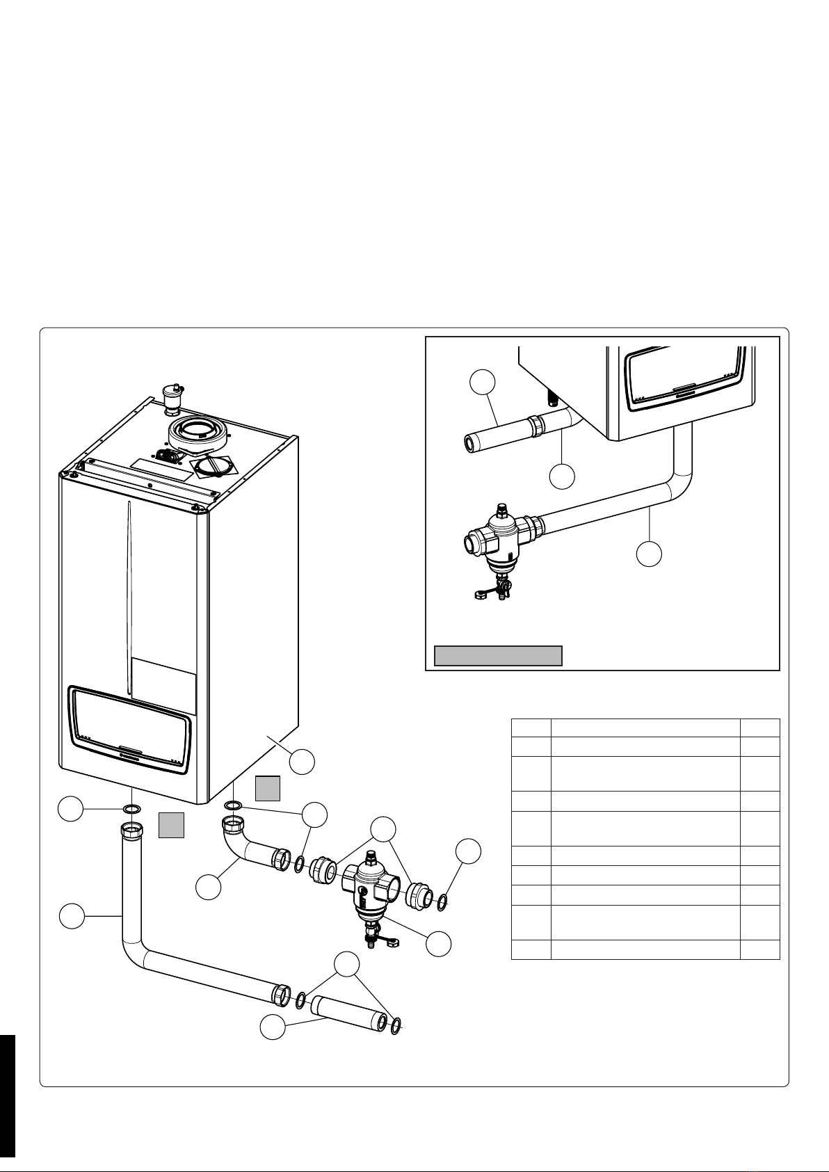
Descrizione
Il defangatore magnetico permette la separazione ed eliminazione
delle impurità presenti nei circuiti idraulici. Le impurità vengono
separate grazie all’azione combinata di un magnete e ad un insieme
di superci metalliche reticolari disposte a raggiera che ne per-
mettono la separazione. Tali impurità possono successivamente
essere evacuate per mezzo della valvola di scarico.
Dati tecnici
Portata max. (m3/h) Volume (l) Peso (kg)
90,69 2,7
• Campo temperatura: 0÷110 °C
• Pressione massima di esercizio: 10 bar
• Fluidi d’impiego: acqua, soluzioni glicolate (max. 30 % di glicole)
• Attacchi defangatore: UNI ISO 228
• Attacchi rubinetto di scarico: 1/2” M + raccordo portagomma
• Attacchi tappo superiore: 1/2”F
General warnings
All Immergas products are protected with suitable transport pack-
aging.
e material must be stored in a dry place protected from the
weather.
is instruction manual provides technical information for installing
the Immergas kit. As for the other issues related to kit installation
(e.g. safety in the workplace, environmental protection, accident
prevention), it is necessary to comply with the provisions specied
in the regulations in force and with the principles of good practice.
Improper installation or assembly of the Immergas appliance and/
or components, accessories, kits and devices can cause unexpected
problems for people, animals and objects. Read the instructions
provided with the product carefully to ensure proper installation.
Installation and maintenance must be performed in compliance
with the regulations in force, according to the manufacturer's in-
structions and by professionally qualied sta, meaning sta with
specic technical skills in the plant sector, as envisioned by the law.
Description
e magnetic dirt separator allows for the separation and elimina-
tion of impurities present in the hydraulic circuits. e impurities
are separated thanks to the combined action of a magnet and a
series of metallic mesh surfaces arranged in a halo shape which
allow for the separation to take place. e impurities can subse-
quently be removed by the discharge valve.
Technical data
Max ow rate (m3/h) Volume (l) Weight (kg)
90.69 2.7
• Temperature range: 0÷110 °C
• Max. working pressure: 10 bar
• Fluids used: water, glycol solution (max. 30 % glycol concen-
tration)
• Dirt separator connections: UNI ISO 228
• Drain cock connections: 1/2” M + pipe-holder connection
• Top cap connection: 1/2”F
IL PRESENTE FOGLIO È DA LASCIARE ALL'UTENTE
ABBINATO AL LIBRETTO ISTRUZIONI DELLA CALDAIA
THIS SHEET MUST BE LEFT WITH THE USER ALONG WITH
THE BOILER INSTRUCTION BOOKLET
Cod. 1.047554 - Rev. ST.007037/000
STD.010229/000

1
Materiali.
• Corpo: ottone CW617N - UNI EN 12165
• Filtro: acciaio inox AISI 304
• Guarnizioni: EPDM
• Magnete: AlNiCo
Funzionamento (Fig. 1).
Il usso entra nel defangatore e subisce un rallentamento tale da
favorire la separazione delle impurità solide presenti nel uido.
Le impurità solide vengono separate in seguito alla collisione con
la maglia metallica (A) e quelle ferrose vengono trattenute dalla
forza di attrazione generata dal magnete (B).
E’ possibile eseguire la pulizia del ltro senza doverlo smontare
e/o spegnere l’impianto, aprendo il rubinetto di intercettazione
(C) e rimuovendo il magnete (B) dal pozzetto di contenimento,
estraendolo verso l’alto
Materials.
• Body: brass CW617N - UNI EN 12165
• Filter: stainless steel AISI 304
• Gaskets: EPDM
• Magnet: AlNiCo
Operation (Fig. 1).
e ow enters the dirt separator and is slowed down, allowing
for the separation of the solid impurities present in the uid. e
solid impurities are separated when they collide with the metal
mesh (A) and ferrous particles are retained by the attraction force
generated by the magnet (B).
e lter can be cleaned without having to remove it and/or switch
o the system, by opening the shut-o cock (C) and removing the
magnet (B) from the container housing, by pulling it upwards.
ATTENZIONE:
Il simbolo riportato sul tappo indica la
presenza di campi magnetici, eventua-
le causa di danni ad apparecchiature
elettroniche (compresi pacemaker) che
siano poste in prossimità.
WARNING:
e symbol on the cap indicates the
presence of magnetic elds, which can
cause damage to electronic devices (in-
cluding pacemakers) that are placed in
close proximity.
STD.010229/000

2
3
4
Manutenzione.
Pulizia del ltro.
Per eseguire la pulizia del ltro senza doverlo smontare e/o spe-
gnere l’impianto, procedere come illustrato sotto.
Tuttavia, per una pulizia più ecace è ideale eseguire queste ope-
razioni in assenza di usso all’interno del defangatore.
1)Durante il funzionamento dell’impianto, lo sporco si deposita
sulla supercie del pozzetto contenente il magnete.
Maintenance.
Cleaning the lter.
To clean the lter without having to remove it and/or switch o
the system, proceed as indicated below.
However, for more eective cleaning, it is advisable to carry out
these steps when the ow to the dirt separator has been shut o.
1)During system function, the dirt is deposited on the surface of
the housing containing the magnet.
2)Rimuovere il magnete dal proprio pozzetto di contenimento,
svitandolo in senso orario.
Lo sporco che si era accumulato sulla supercie del pozzetto si
depositerà nella parte inferiore del defangatore.
2)Remove the magnet from its container housing, unscrewing in
a clockwise motion.
e dirt that has been accumulated on the surface of the housing
will be deposited on the lower part of the dirt separator.
3)Dopo aver atteso qualche minuto, procedere aprendo il rubinetto
di scarico, ruotandolo in senso antiorario.
3)Aer waiting a few minutes, proceed with opening the drain
cock, turning anticlockwise.
STD.010229/000

5
6
4)Una volta che le impurità sono state fatte fuoriuscire, chiudere il
rubinetto di scarico e reinserire il magnete nel proprio pozzetto,
avvitandolo in senso antiorario.
Il defangatore riprenderà il normale funzionamento.
4)Once the impurities have been removed, close the drain cock
again and reinsert the magnet in its housing, screwing in an
anticlockwise motion.
e dirt separator will resume normal function.
Rimozione del ltro.
Nei defangatori lettati è possibile inoltre rimuovere il ltro per
una migliore pulizia, procedendo nel seguente modo:
1)Spegnere l’impianto e intercettare il uido con delle valvole a
sfera, a monte e a valle del defangatore, per evitare che circoli
acqua all’interno del defangatore.
2)Svitare in senso orario la base del defangatore.
3)Rimuovere il ltro dal defangatore e pulirlo.
4)Reinserire il ltro ed avvitare nuovamente la base del defanga-
tore.
Removing the lter.
In addition, the lter can be removed for improved cleaning, by
carrying out the following steps:
1)Switch o the system and stop the uid using ball valves,
upstream and downstream of the dirt separator, to prevent water
circulating inside the dirt separator.
2)Unscrew the base of the dirt separator in a clockwise motion.
3)Remove the lter from the dirt separator and clean it.
4)Reinsert the lter and re-tighten the base of the dirt separator.
STD.010229/000

IT
7
8
300
G 1 1/2"
G 1 1/2"
409.5
851
1666
345
300315
960
220
499
5A
390 345315
1050
G 1 1/2" G 1 1/2"
300 409.6 1098
1913
220
627
5B
ATTENZIONE: Solo per il mercato italiano le caldaie devono essere installate nelle congurazioni con il kit dispositivi sicurezza
INAIL, secondo la raccolta "R".
Dimensioni di montaggio kit defangatore per Victrix Pro 35-55-80 V2 connessione idraulica a destra.
Dimensioni di montaggio kit defangatore per Victrix Pro 100-120-150-180 V2 connessione idraulica a destra.
STD.010229/000

9
10
300
G 1 1/2" G 1 1/2"
409.5 851
1827
343 300 70
713
220
499
5A
G 1 1/2"
1098
627
220
300 409.5
105390250
810
G 1 1/2"
2076
5C
Dimensioni di montaggio kit defangatore per Victrix Pro 35-55-80 V2 connessione idraulica a sinistra.
Dimensioni di montaggio kit defangatore per Victrix Pro 100-120-150-180 V2 connessione idraulica a sinistra.
STD.010229/000

5x
2
6
11
3
5x
1
1
2
4
1
1
6
7
R
M
USCITA SX 12
Montaggio kit defangatore.
Assemblare sul defangatore (4) i nipples (3) assicurandosi di interporre apposito materiale di tenuta quale stoppa o simili.
Collegare sul ritorno (R) della caldaia (7) il tubo (2) e il defangatore (4), precedentemente assemblato con i nipples (3), assicurandosi di
interporre le guarnizioni (1).
Collegare sulla mandata (M) della caldaia (7), in sequenza, il tubo (6) e il tubo (5) assicurandosi di interporre le guarnizioni (1) come
indicato in Fig. 11.
N.B.: Scegliere il tubo (5) della lunghezza adeguata a seconda della tipologia di caldaia (35-55-80-100-120-150-180) e del tipo di connes-
sione da eseguire (sinistra o destra) (vedi Fig. 7, 8, 9 e 10).
Dopo il 1° collaudo in temperatura vericare il serraggio di tutte le tubazioni.
N.B.: i componenti a valle dell'impianto quali vaso d'espansione etc... vanno dimensionati in base alla portata dell'impianto.
Nel caso di montaggio del kit con uscite libere sul lato sinistro è necessario eseguire l'installazione come rappresentato in gura 12.
Attenzione: le caldaie VICTRIX PRO V2 hanno un grado di isolamento elettrico IPX5D e possono essere installate anche all'esterno
mediante gli appositi kit; è opportuno comunque, se installate all'esterno, proteggere dagli agenti atmosferici i kit.
Le caldaie devono essere installate nelle congurazioni e con i propri kit sicurezza originali.
La ditta declina ogni responsabilità qualora
l'installatore non utilizzi i dispositivi ed i kit originali approvati INAIL o li utilizzi impropriamente.
ATTENZIONE: L'installazione a seguire non è valida per il mercato italiano.
Rif Descrizione componenti kit Q.tà
1Guarnizione 44x34x2 6
2Tubo mandata kit batteria
Victrix Pro V2 BP
1
3Nipples ottone G 1 1-2 G 2 mm 2
4Defangatore G2 R146MY018
Victrix Pro V2
1
5A Tubo DN40 G 1 1/2 L.199 1
5B Tubo DN40 G 1 1/2 L.289 1
5C Tubo DN40 G 1 1/2 L.111 1
6Tubo mandata kit defangatore
Victrix Pro V2
1
7Caldaia 1
STD.010229/000

13
14
IE
300
G 1 1/2"
G 1 1/2"
34530070
715
1315
59 851
220
499
5A
G 1 1/2"
627
220
G 1 1/2"
300
57.5
1098
1561
105 390 345
840
5B
Mounting dimensions of dirt separator kit for Victrix Pro 100-120-150-180 V2 (right hydraulic connection).
ATTENTION: e following installation is not valid for the Italian market.
Mounting dimensions of dirt separator kit for Victrix Pro 35-55-80 V2 (right hydraulic connection).
STD.010229/000

15
16
300
G 1 1/2" G 1 1/2"
300343 70
713
59 851
1477
220
499
5A
G 1 1/2"
627
1098
220
300 57.5
G 1 1/2"
1724
105390
250
745
5C
Mounting dimensions of dirt separator kit for Victrix Pro 35-55-80 V2 (le hydraulic connection).
Mounting dimensions of dirt separator kit for Victrix Pro 100-120-150-180 V2 (le hydraulic connection).
STD.010229/000

5x
2
6
17
3
5x
1
1
2
4
1
1
6
7
R
M
LEFT OUTLET 18
Mounting the dirt separator.
Assemble the nipples (3) on the dirt separator (4), making sure to interpose suitable sealing material such as oakum or similar.
Connect the pipe (2) and the dirt separator (4), previously assembled with the nipples (3), to the return (R) line of the boiler (7), making
sure to interpose the gaskets (1).
Connect the pipe (6) and the pipe (5) in sequence to the delivery line (M) of the boiler (7), making sure to place the gaskets (1) in between
as shown in Fig. 17.
N.B.: Choose the pipe (5) of the appropriate length according to the type of boiler (35-55-80-100-120-150-180) and the type of connection
to be made (le or right) (see Fig. 13, 14, 15 and 16).
Aer the 1st temperature test, check the tightness of all the pipes.
N.B.: the components downstream of the system, such as the expansion tank etc..., must be sized according to the ow rate of the system.
If assembling the kit with free outputs on the le side, perform the installation as shown in gure 18.
Attention: the VICTRIX PRO V2 boilers have an IPX5D electric insulation rating and can also be installed outdoors by means of the
relevant kits. However, if installed outdoors, the kit should be protected from the elements.
e boilers must be installed in the congurations and with their own original safety kits.
e factory declines all liability whenever the
installer does not use the devices and approved original kits or uses them improperly.
Ref. Kit components description Q.ty
144x34x2 gasket 6
2Victrix Pro V2 BP set kit ow
pipe
1
3Brass nipples G 1 1-2 G 2 mm 2
4Victrix Pro V2 G2 R146MY018
dirt separator
1
5A DN40 G 1 1/2 L.199 pipe 1
5B DN40 G 1 1/2 L.289 pipe 1
5C DN40 G 1 1/2 L.111 pipe 1
6Victrix Pro V2 dirt separator kit
ow pipe
1
7Boiler 1
STD.010229/000

STD.010229/000

STD.010229/000
Other manuals for VICTRIX PRO V2
2
This manual suits for next models
1
Other Immergas Water Filtration System manuals