IMO Precision Controls Jaguar VXS User manual


Safety at Work
It is the responsibility of the owner,
installer and user to ensure that the installa-
tion of the equipment and the way in which
it is operated and maintained complies with
the requirements of the Health & Safety at
Work Act in the United Kingdom and other
applicable legislation, regulations and
codes of practice in the UK or elsewhere.
Only qualified personnel should install this
equipment, after first reading and under-
standing the information in this publication.
The installation instructions should be
adhered to. Any question or doubt should
be referred to IMO Precision Controls Ltd.
Operational Safety
Users and operators of the equipment must
take all necessary precautions to prevent
damage to equipment and especially to pre-
vent the risk of injury to personnel working
on or near the motor and the driven equip-
ment.
The stop and start inputs should not be
relied upon alone to ensure the safety of
personnel. If a safety hazard could arise
from the unexpected starting of the motor,
an interlock mechanism should be provided
to prevent the motor from running except
when it is safe for it to do so.
Warnings, Cautions and Notes
‘WARNING’, ‘CAUTION’ and ‘NOTE’
paragraphs appear in the text of this instruc-
tion manual wherever they are applicable as
precautionary reminders to installers and
operators.
NOTE Notes call attention to information
that is especially significant in under-
standing and operating the equipment.
Documentation
Every effort has been made by IMO
Precision Controls Ltd to ensure that this
document accurately and completely repre-
sents the Jaguar VXS range of inverters at
the time of going to press. Information
with respect to installation is necessarily
generalised, and the supplier accepts no lia-
bility for contingencies over which he has
no control in respect of the selection, instal-
lation and/or operation of equipment.
IMPORTANT NOTICE
The software described in this User’s Guide
may not apply to earlier VXS inverters
lacking the suffix ‘-EN’.
WARNING
Denotes operating procedures and prac-
tices which, if not correctly followed and
strictly observed, may result in danger,
personal injury or loss of life.
CAUTION
Denotes operating procedures and prac-
tices which, if not correctly followed and
strictly observed, may result in damage to
or destruction of equipment.
Safety Precautions
In line with IMO’s policy of continuous improvement, the contents of this document are
subject to change without prior notice.
Copyright
All rights reserved. No part of this publication may be reproduced or transmitted in any form or by
any means, electronic or mechanical including photocopying, recording, or by by any information
storage or retrieval system without the prior written permission of IMO Precision Controls Ltd.
© IMO Precision Controls Ltd 1996
Part number VXSMAN. Doc. ref. SWK VXS20-VXS400.
Issue IMO-3 Sept 1998

Safety Precautions Inside front cover
Warranty and Helplines Inside back cover
EMC and LVD Conformity Page 2
1 Inspection, Handling & Storage 2
1.1 Product Enquiries 2
1.2 Inspection 2
1.3 Storage Environment 2
1.4 Storage Precautions 2
1.5 Handling 2
2 Specifications 3
2.1 Output Ratings 3
2.2 Input Ratings 3
2.3 Output Frequency 3
2.4 Braking 3
2.5 General 3
3 Common Specifications 4
3.1 Control 4
3.2 Indication 5
3.3 Protection 5
3.4 Operating Environment 5
4 Mechanical Installation 6
4.1 Handling 6
4.2 Environment 6
4.3 Position and Materials 6
4.4 Cooling and Ventilation 6
4.5 Removable Covers and Keypad 7
4.6 Dimensions 7
5 Electrical Installation 10
5.1 Power Connection Block Diagrams 10
5.2 Power Circuits 11
5.3 Control Circuits 12
5.4 Terminals Functions List 14
5.5 Control Circuits and Terminals 15
6 Keypad Functions 16
6.1 Keypad 16
6.2 Keypad Procedures 16
7 Inverter Functions 21
7.1 Functions Data —Range, Units, 21
Resolution & Default
7.2 Descriptions of Functions 26
8 Troubleshooting 44
8.1 Electronic Protection 44
8.2 Trip Alarm Functions 44
8.3 Trip Alarm Codes 44
8.4 Troubleshooting Flow Diagrams 45
9 Braking 55
9.1 Introduction 55
9.2 Overhauling Loads 55
9.3 Calculations for Braking Resistors 56
9.4 Minimum Braking Resistor Values 56
9.5 Protection Circuits 57
10 EMC, RFI and Filters 58
10.1 Electromagnetic
Compatibility (EMC) 58
10.2 Single Phase RFI-FP Filter 60
10.3 Three Phase RFI-FP Filter 61
10.4 RF Ferrite Physical Data 62
11 Supplementary Data 62
11.1 Insulation Testing 62
11.2 Table of Cable Sizes and Maximum
Lengths 63
11.3 Table of Heat Losses 64
1
Contents

1.1 Product Enquiries
If at any time you have a difficulty or a ques-
tion regarding the inverter, please contact
IMO Precision Controls Ltd at the address
inside the back cover of this Manual. The
following information will be required:
(a) Inverter type (from the rating plate).
(b) Serial number (from the rating plate).
(c) Date of purchase.
(d) The nature of the problem — for instance,
the location and extent of damage, the point
which is unclear or the circumstances under
which a malfunction occurred.
1.2 Inspection
Immediately after unpacking the inverter,
please inspect as follows:
Check the rating plate on the side of the
inverter cover to ensure that the inverter speci-
fication corresponds to the order specification.
Inspect the inverter to determine whether the
unit has been damaged in transit. Look for
loose components and damage to any part of
the cover, side panels, mounting brackets or
other components.
1.3 Storage Environment
• Temperature -20oC to +65oC (-4oF to
+149oF) short-term during transport or
storage.
• Relative humidity 20% to 90% non-con-
densing.
• Avoid places where large variations in
temperature occur, even if the relative
humidity is within the specified limits.
Such places could cause condensation or
freezing and should be avoided.
• The inverter should not be placed in direct
sunlight. The surrounding atmosphere should
ideally be dry, free from dust, corrosive or
inflammable gases or vapours, oil mist,
steam, dripping water and vibration. A salt-
laden atmosphere is especially deleterious.
1.4 Storage Precautions
• Do not place the inverter directly onto the
floor. It should always be placed on a stand
or shelf.
• If the inverter is being stored in a less-than-
ideal environment, cover it with a plastic
sheet for protection.
• If there is a likelihood of humidity affecting
the inverter, place a desiccating agent (such
as silica gel) inside the inverter, and then
cover it with a plastic sheet for protection.
1.5 Handling
Be sure to take a firm grip of the chassis of
the unit when carrying the inverter.
2
CAUTION
Hold and lift the inverter by the
chassis/heatsink, not by the cover. The
cover is a protective shield only, and is not
intended for lifting and carrying. Lifting
the inverter by the cover or other front
parts may result in damage.
1 Inspection, Handling and Storage
EMC and LVD Conformity
IMO Jaguar VXS Inverters carrying the suffix -EN as part of their model number conform to EN 60
947-1:1992, Emissions to EN50081-1 and -2 and Immunity to EN50082-1 and -2, and therefore meet
Directive 89/336/EEC relating to Electromagnetic Compatibility. Additionally, they also comply
with DIN VDE 0160/1988 for Over Voltage Category II, Pollution Degree 2, and hence conform to
the protection requirements of Council Directive 73/23/EEC, Low Voltage Directive. Conformity
requires the VXS inverter to be wired and earthed in accordance with the installation instructions in
this User’s Guide and installed within a steel enclosure which satisfies the requirements of
Pollution Degree 2 and used in conjunction with an AC power supply which is recognised Over
Voltage Category II and has an earthed neutral point. Throughout this manual the -EN suffix has
been omitted for simplicity and for economy of space.
Earth terminals. Jaguar VXS… -EN inverters now carry the standard symbol
instead of the lettering ‘GND(PE)’.

2 Specifications
Inverter type VXS… 20-1 40-1 75-1 150-1 220-1 40-3 75-3 150-3 220-3 400-3
2.1 Output Ratings Single-phase Input Three-phase Input
Nominal applied motor kW 0.2 0.4/ 0.75 1.5 2.2 0.4/ 0.75 1.5 2.2 4.0
0.55 0.55
Rated capacity* kVA 0.6 1.2 2.0 3.2 4.4 1.2 1.8 2.7 4.0 6.5
Voltage V 0V to VL
Frequency Hz 0.2Hz to 400Hz
Rated Low PWM freq. A 1.5 3.0 5.0 8.0 11.0 1.6 2.5 3.7 5.5 9.0
current High PWM freq. A 1.3 2.5 4.0 7.0 10.0 1.4 2.1 3.7 5.3 8.7
Overload capability 150% of rated current for 1 minute
200% of rated current for 0.5s
2.2 Input Ratings Single-phase Input Three-phase Input
Rated current (rms) A 2.95 4.1 7.2 14 20 1.3 2.2 4.3 6.0 9.8
Min. supply capacity kVA 0.7 1.2 1.8 3.2 4.5 0.7 1.2 2.2 3.1 5.0
MCB rating with DC reactor A6 6 101020 6 6 6 1010
without DC reactor A 6 10 16 20 32 6 6 10 16 16
Fuse rating with DC reactor A1010203240 6 6 101020
without DC reactor A1010203240 6 6 101020
Phase; Voltage VL; Frequency 1-ph; 200/240V; 50/60Hz 3-ph; 380/415V; 50/60Hz
Voltage +10% to -10% +10% to -15%
Variations Imbalance — Max. 3% of line to line voltage
Frequency +5% to -5%
2.3 Output Frequency Single-phase Input Three-phase Input
Max. frequency Hz 0.2Hz to 400Hz
Base freq. setting range Hz 15Hz to 400Hz
Starting freq. setting range Hz 0.2Hz, 1Hz to 60Hz (minimum unit 1Hz)
Carrier freq. setting range kHz 0.75kHz, 1kHz to 15.6kHz (minimum unit 1kHz)
Accuracy (stability) Analog ±0.2% of Maximum O/P Frequency (25oC ±10oC)
Digital ±0.01% of Maximum O/P Frequency (-10oC to +50oC)
Analog 1/3000 of Max. O/P Frequency
eg 0.2Hz if max. is 60Hz; 0.4Hz if max. is 120Hz, etc
Setting resolution Digital 0.01Hz up to 99.99Hz output frequency and
0.1Hz from 100Hz output frequency upwards
2.4 Braking Single-phase Input Three-phase Input
Braking torque without resistor ≥100% ≥70% ≥40% ≥100% ≥50%
with resistor —≥150% ≥100% ≥150% ≥100%
Starting frequency: 0.2Hz to 60Hz
DC Injection Braking Braking time: 0.01s to 30s
Braking level: 0 to 100% of rated current
2.5 General Single-phase Input Three-phase Input
Heat loss Please refer to data on page 64
Enclosure IP40, all models (side covers in place)
Cooling method Convection Fan-assisted Convection Fan-assisted
Mass kg 1.1 1.6 1.7 2.7 2.8 1.8 1.8 2.7 2.7 3.2
* At 230V single phase or 415V three phase. 3

Control features PWM Sine-weighted PWM output voltage control with dead-time compensation.
Ultra-low acoustic noise realised by high-frequency carrier wave.
Torque Torque Vector control or manual torque boost with slip compensation.
Auto-tune Auto tuning function as standard. Enables automatic calculation of the
total load values of %R and %X.
Operation Key Pad RUN, STOP.
facilities External FWD, REV and coast-to-stop BX. External fault trip THR. Alarm/trip
signal inputs reset RST. Two- or three-wire RUN/STOP control. External selection of
V/f ratio, Accel./Decel., Torque Boost and Thermal Overload for 2nd motor.
Preset speeds Seven preset speeds selection X1, X2, X3; 8 additional preset speeds, X4.
Speed Key Pad Raise and lower speed, ∧and ∨ keys.
reference Potentiometer 1kΩ, 1W external control.
Analog I/P 0 to +5V DC, 0 to +10V DC and 4-20mA DC.
Digital I/P ‘Motorised pot.’, or 7 or 15 preset speeds.
Serial communications RS485 optional.
Voltage-dip ride-through VXS inverters can be operated continuously when the supply voltage is
≥165V (1-ph) or ≥310V (3-ph). Operating time if <165V (1-ph) or
<310V (3-ph) = 15ms. Smooth recovery selectable.
Run status Digital O/P RUN, FDT, FAR, LU, TL, IP (1) selectable outputs at terminal Y1E.
signals Analog O/P At terminal FMA, the following status signals are selectable:
O/P frequency, O/P current, O/P torque %, load factor %.
Pulse O/P At terminal FMP, O/P frequency multiplying factor adjustable from 10
to 100.
Accel/Decel Time 0.01 to 3600s. There are two independently-adjustable sets of accelera-
tion and deceleration times.
Characteristic Choice of linear or two types of S-curve accel/decel pattern.
Voltage/Frequency V/f Automatic AVR control of V/f characteristic at base frequency.
Output voltage at base frequency adjustable from 80V to 240V, 1-ph;
160V to 480V, 3-ph. Base frequency is selectable for two motors.
Frequency Limiter Output frequency can be held within selectable high and low limits.
Bias Analog frequency reference can be biased from -400Hz to +400Hz, in
steps of 1Hz.
Gain An adjustable gain can be applied to the analog frequency reference,
range to 250%.
Skip-frequency Three preset skip (jump) frequencies, 0 to 400Hz in steps of 1Hz.
Bandwidth (hysteresis) for jump frequencies, 0 to 30Hz in steps of 1Hz.
Slip compensation Selectable compensation to maintain speed when load torque changes.
Auto-restart Four selectable modes of operation.
Torque boost Auto Boost adjusts automatically according to the calculated load torque
value.
Manual 31 patterns selectable as follows:
Squared torque characteristic; Proportional torque characteristic;
Weak linear boost… adjustable in 28 steps to… strong linear boost.
4
3 Common Specifications
(1) FDT = Frequency detected; FAR = ‘At speed’ window; LU = Undervoltage protection trip operated; TL =
Inverter at torque limit; IP = Inverter auto-restarted after restoration of I/P power following momentary loss.
3.1 Control

Torque Starting 150%+ at 1Hz. With Torque Vector control, 200%+ at 3Hz.
boost (contin.) Limit When the motor torque reaches a preset level, the torque limit function
automatically controls the output frequency to prevent the inverter from
tripping due to an overload, if selected.
2nd motor operation The following functions are provided for the control of a 2nd motor:
Rated current 2; Base frequency 2; Torque boost 2; Acceleration time
2; Deceleration time 2; Electronic thermal overload relay 2.
3.2 Indication
Operating mode The following operating parameters can be selected to view:
Output frequency; Output current; Output voltage;
Motor synchronous speed (rpm); Line speed (m/min).
Programming mode LED display: Function number and data (refer to pages 18 to 20).
Trip mode LED display: cause of trip. Refer to Function 29, page 32.
3.3 Protection
Supply system surge V Protection to the following level: 1.2 x 50µs, 7kV peak.
Overload trip Selectable electronic thermal overload relay protecting the power output
IGBTs.
Overvoltage trip Detection of overvoltage in the DC bus circuit at the following levels:
Single phase inverters: 400V DC. Three phase inverters: 800V DC.
Undervoltage trip Detection of undervoltage in the DC bus circuit at the following levels:
Single phase inverters: 200V DC. Three phase inverters: 400V DC.
Overtemperature trip Temperature detection of inverter hardware.
Output short circuit trip Inverter output circuit, factory-set short circuit protection.
Earth (ground) fault trip Inverter output circuit, factory-set earth fault protection.
Motor thermal O/L trip Internal electronic thermal overload, user-selectable for application.
The second unit of this function is available for a 2nd motor.
Stall prevention Prevents the inverter tripping on overcurrent when the output current
exceeds a preset limiting level during acceleration, deceleration, or at
steady speed by freezing or reducing the output frequency.
Alarm output Changeover contacts operate when a protective function is activated.
Rating: 48V DC, 0.3A.
Alarm reset Alarm cancelled by either RESET keypad key or terminal RST.
Alarm history The last four alarms are recorded and can be viewed. Refer to
Function 29, page 32.
3.4 Operating Environment
Altitude Derate the inverter if installed above 1000m (3280ft).
Location The inverter is designed for installation in a steel enclosure.
Do not install the inverter in a dusty location or expose to corrosive
gases, oil or water, or direct sunlight.
Ambient temperature -10oC to +50oC (+14oF to +122oF). If ambient temperature exceeds
40oC (104oF), remove inverter side covers.
Ambient humidity 20% to 90% non-condensing.
Vibration 5.9m/s2(0.6G) or less.
5

4.1 Handling
4.2 Environment
• The inverter should be installed in an ade-
quately-ventilated, steel enclosure.
• The inverter is designed to operate at full
rating at an altitude not above 1000m
(3280 ft). Derate if installed above this.
Install the inverter in a location that meets the
following requirements:
• Ambient temperature between -10oC and
+50oC (+14oF to +122oF).
• If the ambient maximum temperature
exceeds 40oC (104oF), remove the venti-
lation covers located one on either side to
allow increased air flow.
For other operating environment specifica-
tions, refer to Section 3.4, page 5.
4.3 Position and Materials
• Position the inverter vertically so that the
inscriptions on the keypad panel are the
right way up.
• Bolt the inverter firmly to a rigid structure.
• The material of the mounting panel should
be able to tolerate the temperature attain-
able by the inverter heatsink, normally
90oC (194oF).
• The fixing bolts should be used with nuts
or washers that will resist vibration.
•Do not overtighten the fixing bolts.
4.4 Cooling and Ventilation
For inverter heat losses refer to page 64.
Observe the minimum clearances shown in the
illustration below.
The inverter should be installed in an enclo-
sure. The minimum clearances to adjacent
equipment must be allowed.
If two or more inverters are to be installed in
6
4 Mechanical Installation
CAUTION
Hold and lift the inverter by the
chassis/heatsink, not by the cover. The
cover is a protective shield only, and is not
intended for lifting and carrying. Lifting
the inverter by the cover or other front
parts may result in damage. 50
Minimum clearances (mm) from the
inverter to any other equipment.
120
120
50
50
50mm
minimum
between
inverters
Inverter(s) mounted on
deflector plate to nullify
the effect of other heat
source(s).
Ventilation should take
account of all other
heat-producing
equipment.
Ventilation should take
account of all other
heat-producing
equipment.
Inverter
the same enclosure, they should ideally be
side by side at a minimum spacing of 50mm.
If an inverter is to be mounted above heat-pro-
ducing equipment of any type, precautions
must be taken to ensure that the heat generated
by the lower unit does not affect the upper. A
deflector plate may be fitted below the invert-
er to nullify the heating effect, as illustrated
on the previous page.
4.5 Removable Covers and Keypad
Front cover
It is not necessary to remove the inverter front
cover for cooling. It should be left in place,
except when wiring up, for safety.
Removable side covers
Removable covers are fitted to the sides of the
inverter. Normally these should be left in
place. If the ambient temperature of the
installation is likely to exceed 40oC, these
covers should be removed.
The temperature within an enclosure should
not exceed 50oC under any circumstances.
Removable keypad
The keypad can be detached from the front
cover and mounted remotely (max. distance
5m).
Two keypad retaining screws can be released
from the back when the front cover is
removed.
A 2m screened connector cable with fitted ter-
minations is available.
7
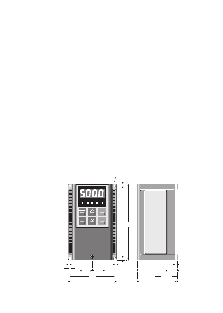
VXS20-1 (Single Phase)
PANEL
CONTROL PRG MODE RUN
Hz A V
r/min m/min
PRG
RESET RUN
FUNC
DATA STOP
*Centrelines of 3 cable entry holes, 18mm dia.
22.5 22.5
93
105
5
666
6
138
150
5
80 45.5
** * *
Removable
side-cover
17
Dimensions in mm
2 holes, 5mm
4.6 Dimensions
8
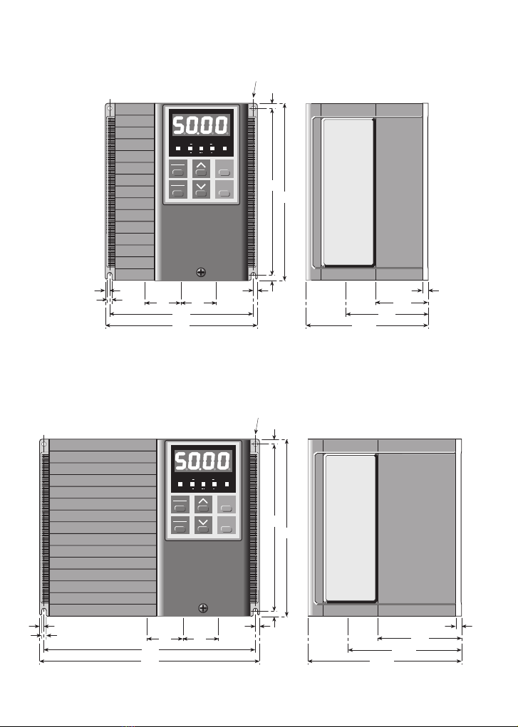
VXS40-1 and VXS75-1 (Single Phase)
VXS40-3 and VXS75-3 (Three Phase)
PANEL
CONTROL PRG MODE RUN
Hz A V
r/min m/min
PRG
RESET RUN
FUNC
DATA STOP
*Centrelines of 3 cable entry holes, 22mm dia.
30 30
128
140
5
666
6
Dimensions in mm
138
150
2 holes, 5mm
46
6
109 75
*** *
Removable
side-cover
PANEL
CONTROL PRG MODE RUN
Hz A V
r/min m/min
PRG
RESET RUN
FUNC
DATA STOP
30 30
188
200
5
666
6
Dimensions in mm
138
150
71 6
100
134
VXS150-1 and VXS220-1 (Single Phase)
VXS150-3 and VXS220-3 (Three Phase)
*Centrelines of 3 cable entry holes, 22mm dia.
*** *
2 holes, 5mm
Removable
side-cover
4.6 Dimensions continued
9
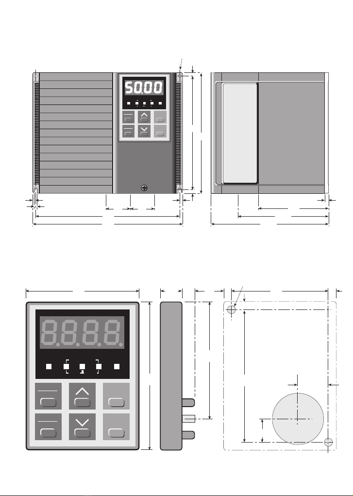
VXS400-3 (Three Phase)
PANEL
CONTROL PRG MODE RUN
Hz A V
r/min m/min
PRG
RESET RUN
FUNC
DATA STOP
30 30
188
200
5
666
6
Dimensions in mm
138
150
86 6
115
149
*Centrelines of 3 cable entry holes, 22mm dia.
*** *
2 holes, 5mm
Removable
side-cover
Keypad and Drilling Pattern for Remote Mounting Dimensions in mm
PANEL
CONTROL PRG MODE RUN
Hz A V
r/min m/min
PRG
RESET RUN
FUNC
DATA STOP
65
85
12.3 7.9
67.5
5 55 5
5
75
12.5 ±0.5
17.5 ±0.5
dia 30
2 holes,
dia 3.5
4.6 Dimensions continued

10
5 Electrical Installation
WARNING
ELECTRICAL SHOCK HAZARD
Do not touch any electrical parts of the
inverter when the power supply is connect-
ed, even if the inverter output is at STOP.
After the power supply has been discon-
nected, the built-in smoothing capacitor
will hold a residual charge. It takes up to
10 minutes for the capacitor to discharge
completely. To avoid danger, wait until the
charge indicator LED is extinguished.
WARNING — SAFETY EARTHING
The inverter chassis, motor base and
equipment enclosure structure should be
earthed in accordance with the national
and local safety specifications in force.
CAUTION
Do not connect any supply voltage that
exceeds the standard voltages and varia-
tions specified on page 3, or the inverter
will be damaged and the Warranty will be
invalidated.
5.1 Power Connection Block Diagrams
These diagrams are not suitable for Electromagnetic Compatibility (EMC), refer to page 58.
For the Table of Cable Sizes and Maximum Lengths, refer to page 63.
L
N
Jaguar
VXS
Inverter
Input
contactor
U
V
W
E
RF
FILTER
(Footprint
type FP)
HRC
Fuse
or MCB
FERRITE
RING
(Two
turns)
Keep distance (and conductors)
between inverter and motor
cable entry as short as possible.
Steel or aluminium Back Plate
Line Load
M
L
N
Link
F
LK
E
Remove paint at
fixing points
Jaguar
VXS
Inverter
Input
contactor
U
V
W
E
RF
FILTER
(Footprint
type FP)
HRC
Fuse
or MCB
FERRITE
RING
(Two
turns)
Keep distance (and conductors)
between inverter and motor
cable entry as short as possible.
Steel or aluminium Back Plate
Line Load
M
L1
Link
E
Remove paint at
fixing points
L2
L3
L1
L2
L3
240V 50/60Hz Single-phase
415V 50/60Hz Three-phase

5.2 Power Circuits
Access to Terminals
Remove the front cover by releasing the single
captive screw near the lower edge of the
cover. Press firmly inwards on the sides of
the cover near the lower edge and lift it away.
Power terminals and control terminals are
now accessible from the front.
Power Input/Output Terminal Blocks
Power Input Circuit
It is essential that the incoming supply cir-
cuit to the inverter is properly protected
against short-circuit and earth faults.
The alternatives are a suitably-rated fused
contactor, MCB or RCD to ensure that the line
and neutral (or all three phases) are operated
simultaneously.
For ratings refer to pages 3 or 63.
Power Output Circuit
Connect a three-phase squirrel-cage motor to
the output terminals U, V, W in the correct
sequence, preferably using screened or
armoured cable. If the operational commands
FWD and REV do not match the desired
direction of motor rotation, interchange any
two of the U, V, W connections. It is not nec-
essary to change the power input connections.
The motor circuit is protected by the inverter
software against overload provided that
Functions 15 & 16 (and Functions 66 & 67 if
applicable) are correctly set. The inverter
automatically protects the power output circuit
against short circuit and earth faults.
The installation of any type of automatic or
semi-automatic switchgear in the inverter out-
put circuit is not recommended (see below)
except for changeover switching when two
motors are supplied from the one inverter.
Power Output Circuit Isolation
An isolator may be installed in the inverter
output circuit for reasons of operational safe-
ty. Auxiliary contacts (early break, late
make), should interface with the inverter con-
trol terminals. On no account should the
isolator be used to control the start/stop
operation of the motor. Consult IMO
Precision Controls Ltd if in any doubt.
11
Single phase inverters VXS40-1 to 220-1
L N P1 (+) DB U V W
L1 L2 L3 P1 (+) DB U V W
Three phase inverters, all sizes
—
Single phase inverter VXS20-1
L N P1 (+) — U V W—
CAUTION
Connect the power supply to the power ter-
minals L, N (1-phase) or L1, L2, L3 (3-
phase), NOT to the output terminals U, V,
W, or to the control terminals.
CAUTION
Do not overtighten terminal screws.
CAUTION
Do not install filter capacitors, power factor
correction capacitors, a surge absorber or
any form of automatic switchgear on the
output side of the inverter.
CAUTION
Motor thermal overload protection is desir-
able. Use either the inverter electronic
overload protection, or a motor thermistor
and thermistor relay.

DC Bus Reactor
NOTE If a reactor is not fitted to the inverter, it
is essential that terminals (+) and P1 remain
linked.
IMO Precision Controls Ltd recommend the
use of a DC reactor to improve the overall
power factor and to reduce the harmonics
reflected into the supply network.
Braking Terminals
Jaguar VXS inverters (except VXS20-1) are
equipped with an internal resistor to apply
dynamic braking as standard. If additional
braking torque is required, an external braking
resistor can be connected to terminals (+) and
DB.
A thermal overload sensor for the resistor is
essential to protect the inverter. The ther-
mal protection should be arranged to trip
the main power supply switch and/or termi-
nal THR, page 15. For further information,
refer to Chapter 9.
5.3 Control Circuits
FWD/REV Input Terminals
At the time of shipment, terminals FWD-P24
are connected by a solid link and Function 02
is set to the default value 0. This puts the
inverter in keypad operating mode, in which
the inverter is operated by the RUN and STOP
keys.
NOTE Whilst terminal FWD or REV is
connected to terminal P24, Function 02
cannot be changed.
To reverse the direction of motor rotation in key-
pad mode, link terminal P24 to REV instead of
FWD as shown in the diagram above.
Control Terminal Block — all models
12
30A
30C
30B
CMC
Y1E
FMP
FMA
X1
BX
X2
RST
X3
C1
X4
13
REV
12
FWD
11
THR
CM
P24
CM
P24
Jaguar
VXS
Terminals linked
(as shipped).
Field
Links changed
to reverse motor
rotation.
Jaguar
VXS
REV
Field
FWD
P24
THR
REV
FWD
P24
THR
WARNING
The RUN and STOP inputs, whether at the
keypad or terminals FWD or REV, should
not be relied upon to ensure the safety of
personnel. If a safety hazard could arise
from the unexpected starting of the motor,
an interlock mechanism should be provided
to prevent the motor from starting except
when it is safe for it to do so.
(+) DB
Jaguar VXS
Inverter
Connections for
an external
braking resistor.
External
braking
resistor
WARNING
The STOP pushbutton on the keypad is
effective ONLY when Function 02 = 0. If
Function 02 is set to 1, an external
RUN/STOP control circuit may be required
at terminals FWD or REV for safety. The
factory-fitted link, shown below, should be
replaced by an external control contact.
Jaguar VXS
Inverter
(+) P1
Connections for a
DC bus reactor.
Remove this link
before connecting
the reactor DC reactor
if required

13
Control Circuits
Use 0.75mm2wiring. All control circuits
should be screened as shown in the illustration
in the adjacent column.
NOTE If control signals originate from a
process controller, it is recommended that
the screening should be terminated at the
source end rather than at the inverter as
shown in all illustrations in this manual.
Control wiring should be installed at least
300mm distant from any power system cables,
and if the two types of conductors must cross
they should be arranged as nearly as possible
at right angles to each other.
The function of each control terminal is given
in the table on the following page.
Control Input Circuits
Contactors or switch contacts should be care-
fully selected for high reliability and absence
of closing defects.
Control Output Circuit
Screening of Control Circuits
Control screening should be connected to a
0V common terminal at the inverter end only,
as shown below. If an external process con-
troller or PLC is used, it is recommended that
the screening should be connected at the end
remote from the inverter.
Suppression of Control Circuits
Sudden changes of flux in the operating coils
of relays and magnetic contactors induce high
transient EMFs which may cause ‘noise’ on
the control circuits, resulting in possible mal-
function of internal or external circuits. It is
advisable to suppress these coils in the manner
shown below.
Y1E
Control output circuit Y1E.
CM
CMC
RC
Jaguar
VXS
Field
+24V DC
from internal
source P24,
or external
(PLC etc).
Output from Y1E —
If internal supply from
P24, connect to
Inverter terminal CM.
If external supply (eg
PLC), connect to PLC
common terminal.
P24
FWD etc
General control input circuit.
24V to 27V DC
power supply
6mA max
CM
Jaguar
VXS
Field
FWD
P24
Screening of external control circuits.
13
12
11
Potentiometer
1kΩ, 1W
Field
contact
CM
C1
Surge suppression for relay and
contactor operating coils.
+
RC
-
CC
C
R
D
D = flywheel diode
RC = relay coil
R = 100Ω, C= 0.1µf
CC = contactor coil
C= capacitor
R= resistor
Typically,
ñ

14
Terminal Terminal Function Description
Power Circuits
L, N Power supply input to inverter Single phase AC power supply.
L1, L2, L3 Power supply input to inverter Three phase AC power supply.
U, V, W Power output to 3-phase motor
(+), P1 DC reactor Optional. Improves p.f. and reduces harmonics.
(+), DB External dynamic braking resistor Optional (DB not available for VXS20-1).
Earth terminal WARNING! Inverter must be earthed.
Frequency Input Reference
11 Common 0V For terminals 12, 13, C1 and FMA.
12 Reference input voltage 0 to +10V DC = 0Hz to max. freq. Z = 22kΩ.
13 Pot. (1kΩ, 1W) power supply +10V DC power supply; max output 10mA.
C1 Reference input current 4 to 20mA DC = 0Hz to max. freq. Z = 250Ω.
Control Inputs
FWD RUN/STOP command — forward -P24 closed = RUN forward; open = decel. & stop.
REV RUN/STOP command — reverse -P24 closed = RUN reverse; open = decel. & stop.
BX Coast-to-stop command -P24 closed = coast to stop.
THR External fault/alarm trip command -P24 open = OH2 trip and coast.
RST Reset inverter after protective trip -P24 closed momentarily (>0.1s) = reset.
X1, X2 ‘Motorised pot.’ X1-P24 closed = accel. time 1 (Function 06).
X2-P24 open = decel. time 1 (Function 07).
X1, X2, X3 Preset frequency select Terminals enable 7 different frequencies to be preset.
X4 Auxiliary control input Four functions according to data set in Function 43:
When F43 = 0, X4-P24 closed selects accel/decel time 2 (Functions 63 and 64).
When F43 = 1, X4 functions as a fourth signal, allowing 15 preset frequencies.
When F43 = 2, X4-P24 closed selects base frequency 2 (Function 62).
When F43 = 3, X4 functions as a ‘hold’ (HLD) signal for 3-wire operation.
Control power supply (two) Internal 24V DC supply. Capacity is adequate to
P24 CAUTION Do not short circuit support all input control circuits plus Y1E output
to either terminal 11 or CM . provided that the load at Y1E is not >50mA.
CM* Common terminals (two) Common for FMP, Y1E and external control contacts.
Monitor Outputs 0 to 10V DC 1mA max. output, proportional to
the value of four parameters (refer to Functions
FMA Analog monitor 09, 40 and 41):
Output frequency; output current;
calculated torque %; load factor %.
FMP Output frequency monitor (pulse) O/P pulse rate = O/P frequency x Function 42.
O/P voltage = 15V peak-to-peak.
* The two terminals CM are at the same potential as terminal 11.
5.4 Terminals Functions List

15
5.5 Control Circuits and Terminals
13
12
11
FWD
REV
THR
CM
X1
X2
X3
X4
BX
RST
P24
CMC
Y1E
30C
30B
30A
Trip
relay
Open collector O/P
P24
CM
FMP
FMA
Pulse O/P
0-10V analog O/P
Keypad Operation Terminal Operation
Analog voltage
freq. ref. input
0V to 10V
(Pot. 1kΩ, 1W)
Programmable
digital
output
+
-
Analog current
freq. ref. input
(4-20mA)
Programmable
analog
output
to terminal 11
(+)
N/C
C1
DB
P1
V
W
U
[L2]
[L3]
[L1]
(+)
DB
P1
V
W
U
Trip
relay
NOTE 2
Open emitter O/P
Refer to Control
O/P Circuit, p.13
Blank
L
N[L2]
[L3]
[L1]Blank
L
N
NOTE 1
13
12
11
FWD
REV
THR
CM
X1
X2
X3
X4
BX
RST
P24
CMC
Y1E
30C
30B
30A
P24
CM
FMA
FMP
C1
NOTE 1
Data in […] applies
to 3-phase inverters
CAUTION
Do not short-circuit terminal P24 to either 11
or CM. Damage may result.
NOTES
1 Terminal DB not available for VXS20-1.
2 Input to terminal THR, (N/C contact)
from external protection relay.
TRIP/ALARM RELAY
Relay is shown with the inverter in either the
power-off or power-on state, condition
‘healthy’.
5.4 Terminals Functions List continued
Terminal Terminal Function Description
Control Outputs
Y1E Open emitter output; 50mA max. Six different functions are available according to
preset selection; refer to Function 54.
CMC Reserved for Y1E output only Refer to the illustration on page 13.
30A, 30B, When no trip, N/O circuit 30A-30C; N/C circuit
30C Alarm output, all trips 30B-30C. When inverter trips, 30A-30C closes.
Rating 48V DC, 0.3A.
16
At Power-on
When power is switched on, the 7-segment
LEDs display flashes together with the (red)
‘Hz’ LED below it if the inverter is in the as-
delivered condition, and the (green) Panel
Control LED also illuminates, not flashing.
The 7-segment LEDs display normally shows
the value set in Function 03 (max. output fre-
quency). The frequency output can be
changed to current, voltage, speed (rpm) or
line speed (m/min). Refer to ‘Changing the
Inverter Output Display’ in the next column.
When one of these has been selected and the
inverter switched off, that same output will
appear at the next power-on.
Keypad Mode
The inverter is factory-set in Keypad Mode
(Functions 01 = 0 and 02 = 0) and is locked
into that mode by the standard link applied to
terminal P24-FWD. If it is desired to oper-
ate the inverter in Terminal Mode, this link
must first be removed before either
Function 01 or Function 02 can be changed.
Functions 01 and 02 can be changed indepen-
dently of each other.
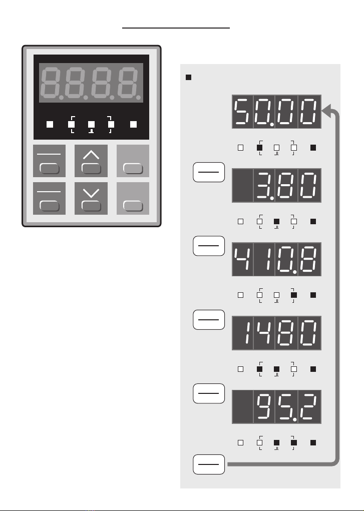
Changing the Inverter Output Display
6 Keypad Functions
6.1 Keypad 6.2 Keypad Procedures
PANEL
CONTROL PRG MODE RUN
Hz A V
r/min m/min
PRG
RESET RUN
FUNC
DATA STOP
PANEL
CONTROL PRG MODE RUN
Hz A V
r/min m/min
PANEL
CONTROL PRG MODE RUN
Hz A V
r/min m/min
Motor
current
PANEL
CONTROL PRG MODE RUN
Hz A V
r/min m/min
Output
voltage
PANEL
CONTROL PRG MODE RUN
Hz A V
r/min m/min
Motor
speed
PANEL
CONTROL PRG MODE RUN
Hz A V
r/min m/min
Line
speed
FUNC
DATA
PRESS
FUNC
DATA
PRESS
FUNC
DATA
PRESS
FUNC
DATA
PRESS
FUNC
DATA
PRESS
Illuminated in RUN mode
Flashing in STOP mode
Illuminated
(not flashing)
in RUN mode

17
STOP Mode Display
7-segment LEDs display flashing. Three out-
put data LEDs flashing.
The 7-segment LEDs display normally shows
the maximum output frequency data set in
Function 03 or whichever other inverter output
value has been selected for display (refer to
Changing the Inverter Output Display, page 16).
When a keypad or a terminal STOP command
is given, the following will be observed:
The RUN (green) LED is extinguished;
The motor decelerates;
The 7-segment LEDs display shows the
decreasing speed (or other output, as
selected);
When the output stops, the LEDs flash;
The 7-segment LEDs display shows
whichever output value has been selected.
RUN Mode Display
7-segment LEDs display and three output data
LEDs are illuminated, not flashing.
The 7-segment LEDs display normally shows
the actual output frequency, or whichever
other inverter output value has been selected
for display (refer to Changing the Inverter
Output Display, page 16).
When a keypad or a terminal RUN command
is given, the following will be observed:
The LEDs stop flashing, become steady;
The RUN (green) LED illuminates;
The motor accelerates;
The 7-segment LEDs display shows the
increasing frequency (or other output, as
selected).
RUN/STOP keys
• Keypad Mode (Function 02 = 0)
‘Panel Control’ LED ON
Start and stop commands. Inverter will accel-
erate and decelerate in the time set in
Functions 06 and 07. It will decelerate when
the STOP key is pressed whether it has
reached full speed or not, and re-accelerate
when the RUN key is pressed, whether it has
reached zero speed or not.
• Terminal Mode (Function 02 = 1)
‘Panel Control’ LED OFF
No effect. Use terminals FWD/REV-P24.
UP and DOWN keys (∧and ∨)
• Keypad Mode (Function 01 = 0)
Change the maximum output frequency data
value set in Function 03.
• Terminal Mode (Function 01 = 1)
No effect. Use terminals 12/C1-11.
• Programming Mode
Refer to the following page.
RUN/STOP terminals FWD/REV-P24
• Keypad Mode (Function 02 = 0)
‘Panel Control’ LED ON
Terminal control is disabled.
• Terminal Mode (Function 02 = 1)
‘Panel Control’ LED OFF
RUN Mode
Close the external contact in the control circuit
connecting P24-FWD or P24-REV.
STOP Mode
Open the external contact in the control circuit
connecting P24-FWD or P24-REV. Refer also
to Function 43 = 3.
INPUT REFERENCE terminals 12-11
and/or C1-11
• Keypad Mode (Function 01 = 0)
Terminal control is disabled.
• Terminal Mode (Function 01 = 1)
Analog frequency control inputs. If both
inputs 12-11 and C1-11 are used, the result-
ing reference is the sum of the two.
WARNING
If a RESET is performed while a RUN
command is present, the inverter will start.
To avoid danger, check that a RUN signal
is not present before performing a RESET.
WARNING
The STOP pushbutton on the keypad is
effective ONLY when Function 02 = 0. If
Function 02 is set to 1, an external
RUN/STOP control circuit may be required
at terminals FWD and REV for safety.

PRG/RESET key
• RUN mode or STOP mode
In either keypad mode or terminal mode, and
provided that the inverter is not in a TRIP
condition, the PRG/RESET key sets the
inverter into PROGRAM mode, allowing the
operator to select the menu of Inverter
Functions (Chapter 7).
When PRG mode is selected, the LED display
shows the Function available, eg F 00, and all
three red LEDs below it illuminate in RUN
mode or flash in STOP mode.
For the explanation of procedures and the use
of the ∧and ∨ keys, refer to the diagrams on
the following pages.
• TRIP Mode
In TRIP mode, the PRG/RESET key resets the
inverter. Refer to Chapter 8.
FUNC/DATA key
• RUN mode or STOP mode
The Function/Data key calls up the Data of the
Function selected in PROGRAM mode.
For the explanation of procedures and the use
of the ∧and ∨ keys, refer to the diagrams on
the following pages.
• STOP Mode
The FUNC/DATA key permits the selection
of one of the 5 different inverter output para-
meters for display on the 7-segment LEDs.
Refer to Changing the Inverter Output
Display, page 16.
NOTES
1 All Functions can be read in both RUN
and STOP modes, and all Functions can
be adjusted in STOP mode. In RUN
mode, some Functions are ‘read only’.
Refer to Chapter 7.
2 If Function Data is protected, adjustment
is not possible. Refer to Function 00
page 26, and Function 57 page 37.
18
This manual suits for next models
4
Table of contents
Popular Inverter manuals by other brands


HQ Power
HQ Power PSIC75 Series user manual

Western Co
Western Co Leonardo Off-Grid 8kW-8000-48 MG user manual

Badger Power Electronics
Badger Power Electronics BPE-HI-3.6K user manual

SolarEdge
SolarEdge SE K Series installation guide

RCT
RCT Power Storage DC 4.0 Setup & installation

Defort
Defort DCI-600 user manual

SMA
SMA Sunny Central 500CP-JP installation manual

Islandaire
Islandaire EZ Series Engineering manual

York
York RVHC-09 Service manual

Samil Power
Samil Power SolarRiver 1100TL-S manual

Power One
Power One AURORA PVI-OUTD-US Series Installation and operator's manual

TECO-Westinghouse
TECO-Westinghouse E510-201-H-U Installation and start-up manual