TECO-Westinghouse E510-201-H-U Installation and operation manual

START-UP AND INSTALLATION MANUAL
DOCUMENT - TECO-E510N1SI
Ver 01: 2017.11
230V Class 1/3~
IP20/NEMA 1
0.4 - 2.2 kW / 0.5 - 3 HP
230V Class 3~
IP20/NEMA 1
0.4 - 30 kW / 0.5 - 40 HP
460V 460V Class 3~
IP20/NEMA 1
0.75- 55 kW / 1 - 75 HP
Read all operating instructions before installing,
connecting (wiring), operating, servicing, or inspecting
the inverter.
Ensure that this manual is made available to the end user of
the inverter.
Store this manual in a safe, convenient location.
T
The manual is subject to change without prior notice.
Refer to the E510 Instruction Manual (www.tecowestinghouse.com).
E510
INVERTER

**** STATEMENT ****
Si Desea descargar el manual en español diríjase a este Link: www.tecowestinghouse.com
Table of Contents
Preface (English)...........................................................................................................................................0-1
Preface (Français) .......................................................................................................................................0-2
1 Safety Precautions (English) ....................................................................................................................1-1
1.1 Before Supplying Power to the Inverter ....................................................................................................1-1
1.2 Wiring........................................................................................................................................................1-2
1.3 Before Operation.......................................................................................................................................1-3
1.4 Parameters Setting ...................................................................................................................................1-3
1.5 Operation ..................................................................................................................................................1-4
1.6 Maintenance, Inspection and Replacement..............................................................................................1-5
1.7 Disposal of the Inverter.............................................................................................................................1-5
1 Consignes de sécurité (Français) ............................................................................................................1-6
1.1 Avant d'alimenter le disque dur.................................................................................................................1-6
1.2 Câblage.....................................................................................................................................................1-6
1.3 Avant l'opération........................................................................................................................................1-7
1.4 Configuration Paramètre...........................................................................................................................1-7
1.5 Opération ..................................................................................................................................................1-8
1.6 Entretien, Inspection et remplacement .....................................................................................................1-8
1.7 Mise au rebut du variateur ........................................................................................................................1-9
2 Model Description......................................................................................................................................2-1
2.1 Nameplate Data........................................................................................................................................2-1
2.2 Inverter Models –Motor Power Rating .....................................................................................................2-2
3 Environment and Installation....................................................................................................................3-1
3.1 Environment..............................................................................................................................................3-1
3.2 Installation.................................................................................................................................................3-2

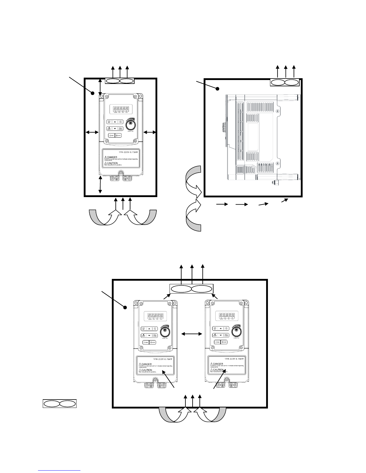
3.3 External View ............................................................................................................................................3-3
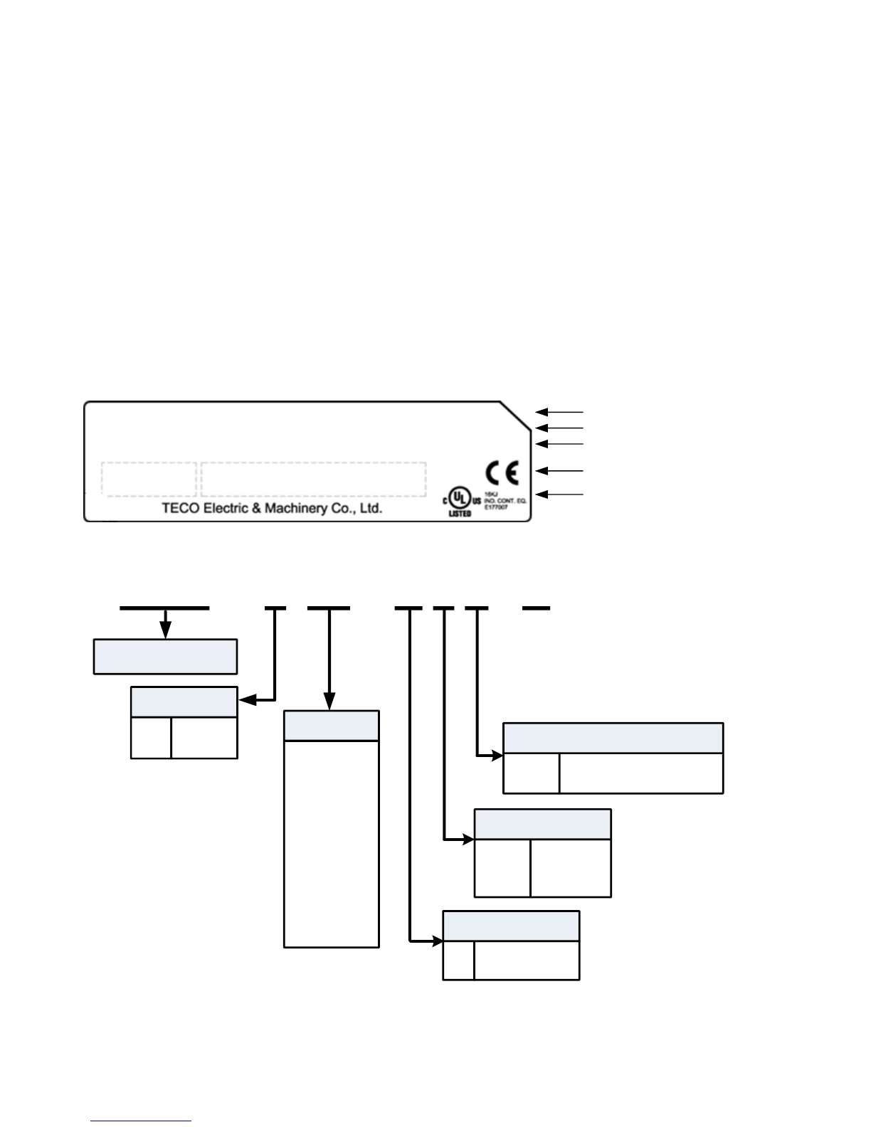
3.4 Warning Labels .........................................................................................................................................3-6
3.5 Removing the Front Cover........................................................................................................................3-7
3.6 Wire Gauges, Tightening Torque, Short Circuit, Circuit Breaker and Fuse Ratings...............................3-14
3.7 Wiring Peripheral Power Devices ...........................................................................................................3-16
3.8 General Wiring Diagram..........................................................................................................................3-18
3.9 User Terminals........................................................................................................................................3-19
3.10 Power Terminals...................................................................................................................................3-22
3.11 Inverter Wiring.......................................................................................................................................3-25
3.12 Input Power and Motor Cable Length...................................................................................................3-27
3.13 Cable Length vs, Carrier Frequency.....................................................................................................3-27
3.14 Installing an AC Line Reactor ...............................................................................................................3-27
3.15 Power Input Wire Size and NFB ...........................................................................................................3-28
3.16 Control Circuit Wiring............................................................................................................................3-28
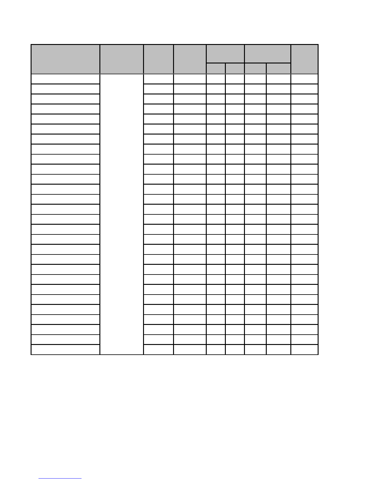
3.17 Inverter Specifications...........................................................................................................................3-29
3.18 General Specifications..........................................................................................................................3-33
3.19 Inverter De-rating Based on Carrier Frequency....................................................................................3-35
3.20 Inverter Dimensions..............................................................................................................................3-38
4. Keypad and Programming Functions.....................................................................................................4-1
4.1 LED/LCD Keypad......................................................................................................................................4-1
4.2 Parameters..............................................................................................................................................4-15
4.3 Commonly Used Parameters..................................................................................................................4-54
5. Check Motor Rotation and Direction.......................................................................................................5-1
6. Speed Reference Command Configuration............................................................................................6-1
6.1 Reference from the Keypad......................................................................................................................6-1
6.2 Reference from an Analog Signal (0-10V / 4-20mA) / Speed Pot ............................................................6-2
6.3 Reference from Serial Communication RS485.........................................................................................6-4
6.4 Reference from Pulse Input ......................................................................................................................6-6
6.5 Change Frequency Unit from Hz to rpm ...................................................................................................6-7

7. Operation Method Configuration (Run / Stop) .......................................................................................7-1
7.1 Run / Stop from the Keypad......................................................................................................................7-1
7.2 Run / Stop from External Switch / Contact or Pushbutton........................................................................7-2
7.3 Run / Stop from Serial Communication RS485 ........................................................................................7-4
8. Motor and Application Specific Settings................................................................................................8-1
8.1 Set Motor Nameplate Data .......................................................................................................................8-1
8.2 Acceleration and Deceleration Time.........................................................................................................8-2
8.3 Volt/Hz Curve Modification (Torque Boost)...............................................................................................8-3
8.4 Emergency Stop........................................................................................................................................8-4
8.5 Forward and Reverse Jog.........................................................................................................................8-5
8.6 Analog Output Setup.................................................................................................................................8-6
9. Using PID Control for Constant Flow / Pressure Applications ............................................................9-1
9.1 What is PID Control...................................................................................................................................9-1
9.2 Connect Transducer Feedback Signal ....................................................................................................9-3
9.3 Engineering Units......................................................................................................................................9-4
9.4 Sleep / Wakeup Function..........................................................................................................................9-5
10 Troubleshooting, Fault Diagnostics and Maintenance ......................................................................10-1
10.1 General .................................................................................................................................................10-1
10.2 Fault Detection Function.......................................................................................................................10-1
10.3 General Troubleshooting ....................................................................................................................10-17
10.4 Inverter Troubleshooting.....................................................................................................................10-18
10.5 Routine and Periodic Inspection .........................................................................................................10-25
10.6 Routine Maintenance..........................................................................................................................10-27
11 Accessories............................................................................................................................................11-1
11.1 Options..................................................................................................................................................11-1
11.2 Braking Resistors..................................................................................................................................11-2
Appendix A: UL Instructions........................................................................................................................ A1

0-1
Preface (English)
The E510 product is an inverter designed to control a three-phase induction motor. Please read this manual
carefully to ensure correct operation, safety and to become familiar with the inverter functions.
The E510 inverter is an electrical / electronic product and must be installed and handled by qualified service
personnel.
Improper handling may result in incorrect operation, shorter life cycle, or failure of this product as well as the
motor.
All E510 documentation is subject to change without notice. Be sure to obtain the latest editions for use or visit
our website at www.tecowestinghouse.com
Available Documentation:
1. E510 Start-up and Installation Manual
2. E510 Instruction Manual
Read this Start-up and Installation Manual in conjunction with E510 Instruction Manual thoroughly before
proceeding with installation, connections (wiring), operation, or maintenance and inspection. Ensure you have
sound knowledge of the device and familiarize yourself with all safety information and precautions before
proceeding to operate the inverter. Read E510 Instruction Manual for detailed description on parameters.
IMPORTANT
For Advanced Installation, Wiring and Programming of the E510 inverter
refer to the E510 Instruction Manual.
Ensure you have sound knowledge of the inverter and familiarize yourself with all safety information and
precautions before proceeding to operate the inverter.
Please pay close attention to the safety precautions indicated by the warning and caution symbol.
Warning
Failure to ignore the information indicated by the warning symbol may result in
death or serious injury.
Caution
Failure to ignore the information indicated by the caution symbol may result in
minor or moderate injury and/or substantial property damage.

0-2
Préface (Français)
Le produit est un lecteur conçu pour commander un moteur à induction triphasé. lire attentivement ce
manuel pour garantir le bon fonctionnement, la sécurité et pour se familiariser avec les fonctions
d'entraînement.
Le lecteur est un appareil électrique / électronique et doit être installé et géré par un personnel qualifié
Une mauvaise manipulation peut entraîner un fonctionnement incorrect, cycle de vie plus court, ou l'échec
de ce produit ainsi que le moteur.
Tous les documents sont sujets à changement sans préavis. Soyez sûr d'obtenir les dernières éditions de
l'utilisation ou visitez notre site Web
Lire le manuel d'instructions avant de procéder à l'installation, les connexions (câblage), le fonctionnement
ou l'entretien et l'inspection.
Vérifiez que vous avez une bonne connaissance de l'entraînement et de vous familiariser avec les
consignes de sécurité et les précautions avant de procéder à fonctionner le lecteur.
prêter attention aux consignes de sécurité indiquées par l'avertissement et symbole Attention .
Avertissement
ignorer les informations indiquées par le symbole d'avertissement peut
entraîner la mort ou des blessures graves.
Attention
ignorer les informations indiquées par le symbole de mise en garde peut
entraîner des blessures mineures ou modérées et / ou des dommages
matériels importants.

1-1
1. Safety Precautions (English)
1.1 Before supplying Power to the Inverter
Warning
The main circuit must be correctly wired. For single phase supply use input terminals (R/L1, T/L3) and for
three phase supply use input terminals (L1(L), L2, L3(N)). Terminals T1, T2, T3 must only be used to
connect the motor. Connecting the input supply to any of the T1, T2 or T3 terminals will cause damage to
the inverter.
Caution
To avoid the front cover from disengaging or other physical damage, do not carry the inverter by
its cover. Support the unit by its heat sink when transporting. Improper handling can damage the
inverter or injure personnel, and should be avoided.
To avoid the risk of fire, do not install the inverter on or near flammable objects. Install on
nonflammable objects such as metal surfaces.
If several inverters are placed inside the same control panel, provide adequate ventilation to
maintain the temperature below 40°C/104°F (50°C/122°F without a dust cover) to avoid
overheating or fire.
When removing or installing the digital operator, turn off the power first, and then follow the
instructions in this manual to avoid operator error or loss of display caused by faulty connections.
Warning
This product is sold subject to IEC 61800-3. In a domestic environment this product may cause radio
interference in which case the user may need to apply corrective measures.

1-2
1.2 Wiring
Warning
Always turn OFF the power supply before attempting inverter installation and wiring of the user
terminals.
Wiring must be performed by a qualified personnel / certified electrician.
Make sure the inverter is properly grounded. (230V Class: Grounding impedance shall be less
than 100Ω. 460V Class: Grounding impedance shall be less than 10Ω.)
Please check and test emergency stop circuits after wiring. (Installer is responsible for the correct
wiring.)
Never touch any of the input or output power lines directly or allow any input of output power lines to
come in contact with the inverter case.
Do not perform a dielectric voltage withstand test (megger) on the inverter this will result in inverter
damage to the semiconductor components.
Caution
The line voltage applied must comply with the inverter’s specified input voltage. (See product
nameplate section 2.1)
Use wire gauge recommendations and torque specifications. (See Wire Gauge and Torque
Specification section 3.10)
Never connect input power to the inverter output terminals T1, T2, T3.
Do not connect a contactor or switch in series with the inverter and the motor.
Do not connect a power factor correction capacitor or surge suppressor to the inverter output.
Ensure the interference generated by the inverter and motor does not affect peripheral devices.

1-3
1.3 Before Operation
Warning
Make sure the inverter capacity matches the parameters 13-00.
Reduce the carrier frequency (parameter 11-01) If the cable from the inverter to the motor is
greater than 80 ft (25m). A high-frequency current can be generated by stray capacitance
between the cables and result in an overcurrent trip of the inverter, an increase in leakage
current, or an inaccurate current readout.
Be sure to install all covers before turning on power. Do not remove any of the covers while power to
the inverter is on, otherwise electric shock may occur.
Do not operate switches with wet hands, otherwise electric shock may result.
Do not touch inverter terminals when energized even if inverter has stopped, otherwise electric shock
may result.
1.4 Parameter Setting
Caution
Do not connect a load to the motor while performing a rotational auto-tune.
Make sure the motor can freely run and there is sufficient space around the motor when
performing a rotational auto-tune.

1-4
1.5 Operation
Warning
Be sure to install all covers before turning on power. Do not remove any of the covers while power to
the inverter is on, otherwise electric shock may occur.
Do not connect or disconnect the motor during operation. This will cause the inverter to trip and
may cause damage to the inverter.
Operations may start suddenly if an alarm or fault is reset with a run command active. Confirm that no
run command is active upon resetting the alarm or fault, otherwise accidents may occur.
Do not operate switches with wet hands, otherwise electric shock may result.
It provides an independent external hardware emergency switch, which emergently shuts down the
inverter output in the case of danger.
If automatic restart after power recovery (parameter 07-00) is enabled, the inverter will start
automatically after power is restored.
Make sure it is safe to operate the inverter and motor before performing a rotational auto-tune.
Do not touch inverter terminals when energized even if inverter has stopped, otherwise electric shock
may result.
Do not check signals on circuit boards while the inverter is running.
After the power is turned off, the cooling fan may continue to run for some time.
Caution
Do not touch heat-generating components such as heat sinks and braking resistors.
Carefully check the performance of motor or machine before operating at high speed, otherwise
Injury may result.
Note the parameter settings related to the braking unit when applicable.
Do not use the inverter braking function for mechanical holding, otherwise injury may result.
Do not check signals on circuit boards while the inverter is running.

1-5
1.6 Maintenance, Inspection and Replacement
Warning
Wait a minimum of five minutes after power has been turned OFF before starting an inspection. Also
confirm that the charge light is OFF and that the DC bus voltage has dropped below 25Vdc.
Never touch high voltage terminals in the inverter.
Make sure power to the inverter is disconnected before disassembling the inverter.
Only authorized personnel should perform maintenance, inspection, and replacement operations.
(Take off metal jewelry such as watches and rings and use insulated tools.)
Caution
The Inverter can be used in an environment with a temperature range from 14 -104°F (-10-40°C)
and relative humidity of 95% non-condensing.
The inverter must be operated in a dust, gas, mist and moisture free environment.
1.7 Disposal of the Inverter
Caution
Please dispose of this unit with care as an industrial waste and according to your required local
regulations.
The capacitors of inverter main circuit and printed circuit board are considered as hazardous
waste and must not be burned.
The Plastic enclosure and parts of the inverter such as the top cover board will release harmful
gases if burned.

1-6
1. Consignes de sécurité (Français)
1.1 Avant d'alimenter le disque dur
Avertissement
Le circuit principal doit être correctement câblée. Pour les terminaux monophasés d'approvisionnement
de l'utilisation des intrants (R/L1, T/L3) et de trois bornes d'entrée de l'utilisation de l'offre de phase (R/L1,
S/L2, T/L3). U/T1, V/T2, W/T3 ne doivent être utilisés pour connecter le moteur. Raccordement de
l'alimentation d'entrée à l'un des U/T1, V/T2 W/T3 ou bornes risque d'endommager le lecteur.
Attention
Pour éviter que le couvercle ne se désengage ou de tout autre dommage physique, ne portez pas le
lecteur par son couverture. Soutenir le groupe par son dissipateur de chaleur lors du transport. Une
mauvaise manipulation peut endommager le lecteur ou blesser le personnel, et doit être évitée.
Pour éviter que les risques d'incendie, ne pas installer le lecteur sur ou à proximité d'objets inflammables.
Installer sur des objets ininflammables comme les surfaces métalliques.
Si plusieurs disques sont placés dans le même panneau de contrôle, fournir une ventilation adéquate pour
maintenir la température en dessous de 40 ° C/104 ° F (50 ° C/122 ° F sans housse de protection) pour
éviter la surchauffe ou incendie.
Lors d'un retrait ou d'installation de l'opérateur numérique, éteignez-le d'abord, puis de suivre les
instructions de ce manuel pour éviter les erreurs de l'opérateur ou de la perte de l'affichage causé par des
connexions défectueuses.
Avertissement
Lors d'un retrait ou d'installation de l'opérateur numérique, éteignez-le d'abord, puis de suivre les
instructions de ce manuel pour éviter les erreurs de l'opérateur ou de la perte de l'affichage causé par des
connexions défectueuses....
1.2 Câblage
Avertissement
Coupez toujours l'alimentation électrique avant de procéder à l'installation d'entraînement et le câblage
des terminaux utilisateurs.
Le câblage doit être effectué par un personnel qualifié / électricien certifié.
Assurez-vous que le lecteur est correctement mis à la terre. (220V Classe: impédance de mise à la terre
doit être inférieure à 100ΩClasse 440V:. Impédance de mise à la terre doit être inférieure à 10Ω.)
vérifier et tester mes circuits d'arrêt d'urgence après le câblage. (L’Installateur est responsable du
câblage.)
Ne touchez jamais de l'entrée ou de lignes électriques de sortie permettant directement ou toute entrée ou
de lignes de puissance de sortie à venir en contact avec le boîtier d'entraînement.
Ne pas effectuer un test de tenue en tension diélectrique (mégohmmètre) sur le disque dur ou cela va
entraîner des dommages de lecture pour les composants semi-conducteurs.

1-7
Attention
La tension d'alimentation appliquée doit se conformer à la tension d'entrée spécifiée par le lecteur. (Voir
la section signalétique du produit)
Raccorder la résistance de freinage et de l'unité de freinage sur les bornes assignées.
Ne pas brancher une résistance de freinage directement sur les bornes CC P (+) et N (-), sinon risque
d'incendie.
Utilisez des recommandations de la jauge de fil et les spécifications de couple. (Voir Wire Gauge et la
section de spécification de couple)。
Ne jamais brancher l'alimentation d'entrée aux bornes onduleur de sortie U/T1, V/T2, W/T3.
Ne pas brancher un contacteur ou interrupteur en série avec le variateur et le moteur.
Ne branchez pas un facteur condensateur de correction de puissance ou suppresseur de tension à la
sortie du variateur。
S'assurer que l'interférence générée par l'entraînement et le moteur n'a pas d'incidence sur les
périphériques.
1.3 Avant l'opération
Avertissement
Assurez-vous que la capacité du disque correspond aux paramètres de notation avant d'alimenter.
Réduire le paramètre de la fréquence porteuse si le câble du variateur au moteur est supérieure à 80 pi
(25 m). Un courant de haute fréquence peut être générée par la capacité parasite entre les câbles et
entraîner un déclenchement de surintensité du variateur, une augmentation du courant ou d'une lecture
actuelle inexactes.
Veillez à installer tous les couvercles avant de l'allumer. Ne retirez pas les capots pendant que
l'alimentation du lecteur est allumé, un choc électrique peut se produire autrement.
Ne pas actionner d'interrupteurs avec les mains mouillées, un choc électrique pourrait survenir autrement.
Ne touchez pas les bornes d'entraînement lorsqu'il est alimenté, même si le lecteur est arrêté, un choc
électrique pourrait survenir autrement.
1.4 Configuration Paramètre
Attention
Ne branchez pas une charge pour le moteur tout en effectuant un auto-tune.
Assurez-vous que le moteur peut fonctionner librement et il y a suffisamment d'espace autour du moteur
lors de l'exécution d'un auto-tune rotation.

1-8
1.5 Opération
Avertissement
Veillez à installer tous les couvercles avant de l'allumer. Ne retirez pas les capots pendant que
l'alimentation du lecteur est allumé, un choc électrique peut se produire autrement.
Ne pas brancher ou débrancher le moteur pendant le fonctionnement. Le variateur pourrai se déclencher
et ainsi endommager le lecteur.
Les opérations peuvent commencer soudainement si une alarme ou un défaut est réarmé avec un ordre
de marche active. Assurez-vous qu'un ordre de marche est actif lors de la réinitialisation de l'alarme ou
de défaut, autrement des accidents peuvent se produire.
Ne pas actionner d'interrupteurs avec les mains mouillées, un choc électrique pourrait survenir.
Un interrupteur d'urgence externe indépendant est fourni, qui s'arrête en urgence vers le bas la sortie de
l'onduleur en cas de danger.
Si le redémarrage automatique après une récupération d'énergie est activée, le variateur démarrera
automatiquement après le rétablissement du courant.
Assurez-vous qu'il est sûr de faire fonctionner le variateur et le moteur avant d'effectuer un auto-tune
rotation.
Ne touchez pas les bornes d'entraînement lorsqu'il est alimenté même si l’onduleur s'est arrêté, un choc
électrique pourrait survenir .
Ne pas contrôler les signaux sur les circuits pendant que le lecteur est en marche.
Après la mise hors tension, le ventilateur de refroidissement peut continuer à fonctionner pendant un
certain temps.
Attention
Ne touchez pas les composants générant de la chaleur tels que radiateurs et des résistances de
freinage.
Vérifiez soigneusement la performance du moteur ou de la machine avant d'utiliser à grande vitesse,
sous peine de blessure.
Notez les réglages des paramètres liés à l'unité de freinage lorsque applicable.
Ne pas utiliser la fonction de freinage d'entraînement pour un maintien mécanique, sous peine de
blessure.
Ne pas contrôler les signaux sur les circuits pendant que le lecteur est en marche.
1.6 Entretien, Inspection et remplacement
Avertissement
Attendre un minimum de 5 minutes après que l'alimentation a été débranchée avant de commencer une
inspection. Vérifiez également que le voyant de charge est éteint et que la tension du bus cc a chuté
au-dessous de 25Vdc.
Ne jamais toucher les bornes à haute tension dans le lecteur.
Assurez-vous que l'alimentation du lecteur est débranché avant de démonter le lecteur.
Seul le personnel autorisé peuvent faire l'entretien, l'inspection et les opérations de remplacement.
(Enlevez les bijoux en métal tels que les montres et les bagues et utiliser des outils isolés.)

1-9
Attention
Le variateur peut être utilisé dans un environnement avec une gamme de température allant de
14 ° -104 ° F (10-40 ° C) et l'humidité relative de 95% sans condensation.
Le variateur doit être utilisé dans un environnement sans poussière, gaz, vapeur et humidité.
1.7 Mise au rebut du variateur
Attention
jeter cet appareil avec soin comme un déchet industriel et selon les réglementations locales nécessaires.
Les condensateurs du circuit principal d'entraînement et circuits imprimés sont considérés comme des
déchets dangereux et ne doivent pas être brûlés.
The Plastic enclosure and parts of the drive such as the top cover board will release harmful gases if
burned.

2-1
2. Model Description
2.1 Nameplate Data
It is essential to verify the E510 inverter nameplate and make sure that the E510 inverter has the correct rating so
it can be used in your application with the proper sized AC motor.
Unpack the E510 inverter and check the following:
(1) The E510 inverter start-up and installation manual (this document) are contained in the package.
(2) The E510 inverter has not been damaged during transportation there should be no dents or parts missing.
(3) The E510 inverter is the type you ordered. You can check the type and specifications on the main nameplate.
(4) Check that the input voltage range meets the input power requirements.
(5) Ensure that the motor HP matches the motor rating of the inverter.
(1HP = 0.746 kW)
Product Name and Motor Rating
Input Power Specifications
Output Power Specifications
Series No
UL and CE Marks
PRODUCT: E510-2P5-H-U MOTOR RATING: 0.5 HP
INPUT : AC 1/3PH 200-240V (+10%,-15%) 50/60hz 8.5/4.5A
OUTPUT : AC 3PH 0-599 Hz 3.1A IP20/NEMA 1
MODEL : 11-201-20-2P5-00
P/N BARCODE S/N BARCODE
C
Model Identification
E510 Inverter Series
E510 - 2 10 - H 1 F - U
2:
4:
200-240V
380-480V
Voltage Rating
Motor Rating
H: Standard Type
Operator Type
1:
Blank:
3:
1Ph
1Ph or 3Ph
3Ph
Input
Blank:
F:
None
EMC Filter + STO *
EMC Filter
P5: 0.5 HP
01: 1 HP
02: 2 HP
03: 3 HP
05: 5 HP
08: 7.5 HP
10: 10 HP
15: 15 HP
20: 20 HP
30: 30 HP
40: 40 HP
50: 50 HP
60: 60 HP
75: 75 HP
*F Version models are not available as standard product in Americas.

2-2
2.2 Inverter Models –Motor Power
IP20 / NEMA 1 Type –200V Class
Model
Supply
voltage
(Vac)
Horse
Power
(HP)
Motor
(kW)
EMC
Filter
STO
Function
Frame
Size
V
X
V
X
E510-2P5-H-U
1 Phase
200~240V
+10%-15%
50/60Hz
0.5
0.4
◎
◎
1
E510-201-H-U
1
0.75
◎
◎
1
E510-202-H-U
2
1.5
◎
◎
2
E510-203-H-U
3
2.2
◎
◎
2
E510-2P5-H1F-U*
1 & 3 Phase
200~240V
+10%-15%
50/60Hz
0.5
0.4
◎
◎
1
E510-201-H1F-U*
1
0.75
◎
◎
1
E510-202-H1F-U*
2
1.5
◎
◎
2
E510-203-H1F-U*
3
2.2
◎
◎
2
E510-202-H3-U
3 Phase
200~240V
+10%-15%
50/60Hz
3 Phase
2
1.5
◎
◎
1
E510-205-H3-U
5
4
◎
◎
2
E510-208-H3-U
7.5
5.5
◎
◎
3
E510-210-H3-U
10
7.5
◎
◎
3
E510-215-H3-U
15
11
◎
◎
4
E510-220-H3-U
20
15
◎
◎
4
E510-225-H3-U
25
18.5 / 22
◎
◎
5
E510-230-H3-U
30
22 / 30
◎
◎
6
E510-240-H3-U
40
30 / 37
◎
◎
6
* F Version models are not available as standard product in Americas.
V: Built-in
X: None

2-3
IP20 / NEMA 1 Type –400V Class
Model
Supply
voltage
(Vac)
Horse
Power
(HP)
Motor
(kW)
EMC
Filter
STO Function
Frame
Size
V
X
V
X
E510-401-H3-U
3 Phase
380~480V
+10%-15%
50/60Hz
1
0.75
◎
◎
1
E510-402-H3-U
2
1.5
◎
◎
1
E510-403-H3-U
3
2.2
◎
◎
2
E510-405-H3-U
5
4
◎
◎
2
E510-408-H3-U
7.5
5.5
◎
◎
3
E510-410-H3-U
10
7.5
◎
◎
3
E510-415-H3-U
15
11
◎
◎
3
E510-420-H3-U
20
15
◎
◎
4
E510-425-H3-U
25
18.5
◎
◎
4
E510-430-H3-U
30
22 / 30
◎
◎
5
E510-440-H3-U
40
30 / 37
◎
◎
6
E510-450-H3-U
50
37 / 45
◎
◎
6
E510-460-H3-U
60
45 / 55
◎
◎
6
E510-475-H3-U
75
55 / 75
◎
◎
6
E510-401-H3F-U*
1
0.75
◎
◎
1
E510-402-H3F-U*
2
1.5
◎
◎
1
E510-403-H3F-U*
3
2.2
◎
◎
2
E510-405-H3F-U*
5
4
◎
◎
2
E510-408-H3F-U*
7.5
5.5
◎
◎
3
E510-410-H3F-U*
10
7.5
◎
◎
3
E510-415-H3F-U*
15
11
◎
◎
3
E510-420-H3F-U*
20
15
◎
◎
4
E510-425-H3F-U*
25
18.5
◎
◎
4
E510-430-H3F-U*
30
22 / 30
◎
◎
5
E510-440-H3F-U*
40
30 / 37
◎
◎
6
E510-450-H3F-U*
50
37 / 45
◎
◎
6
E510-460-H3F-U*
60
45 / 55
◎
◎
6
E510-475-H3F-U*
75
55 / 75
◎
◎
6
* F Version models are not available as standard product in Americas.
V: Built-in
X: None

3-1
3. Environment and Installation
3.1 Environment
The environment will directly affect the proper operation and the life span of the inverter. To ensure
that the inverter will give maximum service life, please comply with the following environmental
conditions:
Protection
Protection Class
IP20 / NEMA 1 (Depending on models)
Operating
Temperature
IP20 / NEMA 1 type:
Inside: -10°C - +50°C (14-122 °F) (without sticker / dust cover)
Outside: -10°C - +40°C (14-104 °F) (with sticker / dust cover)
If several inverters are placed in the same control panel, provide additional cooling
And ventilation to maintain ambient temperatures below 40°C (104 °F)
Storage
Temperature
-20°C - +60°C (-4 -140 °F)
Humidity:
95% non-condensing
Relative humidity 5% to 95%, free of moisture.
(Follow IEC60068-2-78 standard)
Altitude:
< 1000m (3,281 ft.)
Installation Site:
Avoid exposure to rain or moisture.
Avoid direct sunlight.
Avoid oil mist and salinity.
Avoid corrosive liquid and gas.
Avoid dust, lint fibers, and small metal filings.
Keep away from radioactive and flammable materials.
Avoid electromagnetic interference (soldering machines, power machines).
Avoid vibration (stamping, punching machines etc.).
Add a vibration-proof pad if the situation cannot be avoided.
Shock
Maximum acceleration: 1G (9.8m/s²), for <20Hz
Maximum acceleration: 0.6G (5.88m/s²), for 20 - 50Hz (IEC60068-2-6 standard)

3-2
3.2 Installation
Provide sufficient air circulation space for cooling as shown in examples below. Install the Inverter on
surfaces that provide good heat dissipation. Frame1 models:2P5 / 201 / 202 (three phase) / 401 / 402.
Side by side installation
Provide the necessary physical space and cooling based on the ambient temperature and the heat loss in
the panel (2P5 / 201/ 202 / 401 / 402).
Cooling fan
Front view Side view
4.8” / 12cm
2” / 5cm
4.8” / 12cm
2” / 5cm
Inside
Enclosure
Inside
Enclosure
2” / 5cm
Enclosure
This manual suits for next models
42
Table of contents
Other TECO-Westinghouse Inverter manuals

TECO-Westinghouse
TECO-Westinghouse MA7200 PLUS Instruction manual

TECO-Westinghouse
TECO-Westinghouse L510-1P2-H1-U Installation and operation manual

TECO-Westinghouse
TECO-Westinghouse F510 Series User manual

TECO-Westinghouse
TECO-Westinghouse MA7200 PLUS User manual

TECO-Westinghouse
TECO-Westinghouse A510 User manual

TECO-Westinghouse
TECO-Westinghouse A510 User manual

TECO-Westinghouse
TECO-Westinghouse FLUXMASTER 100 Series User manual

TECO-Westinghouse
TECO-Westinghouse PA7300 Series User manual

TECO-Westinghouse
TECO-Westinghouse PA7300 Series Instruction manual

TECO-Westinghouse
TECO-Westinghouse E510 Installation and operating manual