Impact Subsea ISD4000 User manual

www.impactsubsea.com
www.impactsubsea.comwww.impactsubsea.com
www.impactsubsea.com
Innovative Underwater Products
Innovative Underwater ProductsInnovative Underwater Products
Innovative Underwater Products
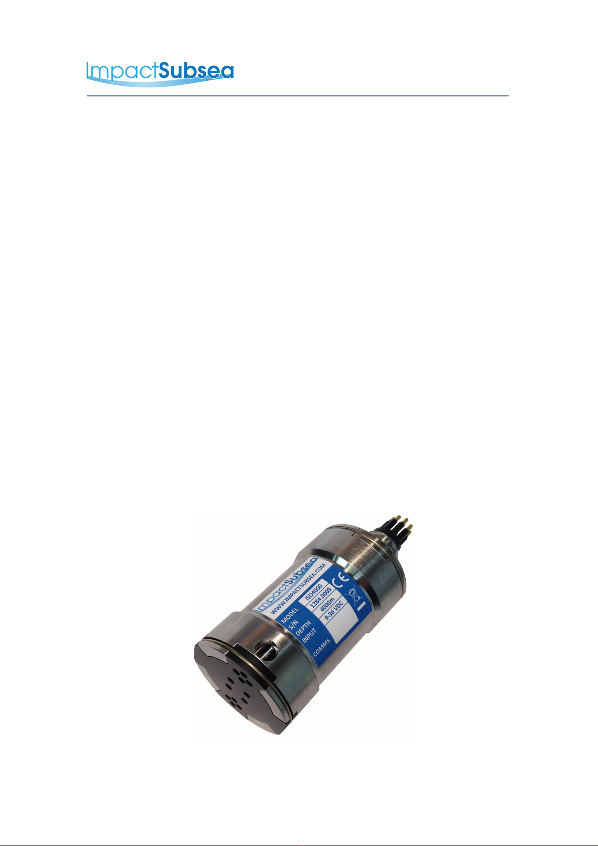
ISD4000
Depth & Temperature
Sensor
Installation & Operation
Manual
Revision: 1.0
Date: 01/02/2016
Impact Subsea Ltd
T. +44 (0) 1224 460 850
E. info impactsubsea.co.uk
W. www.impactsubsea.com

Contents
1.0 Introduction.................................................................................................................................3
2.0 Specification................................................................................................................................4
2.1 Unit Overview .................................................................................................................4
2.2 Unit Dimensions..............................................................................................................4
2.3 Depth, Temperature & HMRU.........................................................................................5
2.4 Communications, Power & Physical...............................................................................5
3.0 Overview.....................................................................................................................................6
4.0 Installation .............................................................................................................................7
4.1 Location............................................................................................................................7
4.1.1 Pressure (For Maximising Depth Measurement Performance).............................7
4.1.2 Magnetic Disturbers (For Maximising Heading Performance).............................7
4.1.3 Alignment with Vehicle (For Maximising Pitch/Roll Accuracy)..........................8
4.1.4 Heat Sources (For Maximising Temperature Accuracy).......................................8
4.2 Mounting .........................................................................................................................9
4.3 Electrical .......................................................................................................................10
4.3.1 Connector Pin Out..............................................................................................10
4.3.2 Connector Mating...............................................................................................11
4.3.3 Connector Cleaning............................................................................................11
4.4 Pressure Tare..................................................................................................................11
5.0 Calibration................................................................................................................................12
6.0 Software & ISD4000 Configuration.........................................................................................13
6.1 Establishing Communications with the ISD4000..........................................................13
6.2 Configuring the ISD4000.............................................................................................15
6.2.1 Setup..........................................................................................................16
6.2.2 Orientation.................................................................................................16
6.2.3 Comms.......................................................................................................16
6.2.4 Depth Interface Settings............................................................................17
6.2.5 Attitude and Heading Interface Settings....................................................17
6.2.6 Load...........................................................................................................17
6.2.7 Save...........................................................................................................17
6.2.8 Default.......................................................................................................18
6.2.9 Tare............................................................................................................18
6.2.10 Calibrate (Gauge Logo).............................................................................18
6.2.11 Calibrate (Thermometer Logo)..................................................................18
6.2.12 Calibrate (Magnet Logo)...........................................................................18
6.2.13 Bootload....................................................................................................18
7.0 Servicing....................................................................................................................................19
8.0 Warranty....................................................................................................................................20
9.0 Technical Support .....................................................................................................................21
Every effort is made to ensure that information within this document is up to date. However, information within this
document is subject to change without notice, in-line with our commitment to continuous product development and
improvement.
www.impactsubsea.com
www.impactsubsea.comwww.impactsubsea.com
www.impactsubsea.com
Innovative Underwater Products
Innovative Underwater ProductsInnovative Underwater Products
Innovative Underwater Products
1.0 Introduction
The ISD4000 sensor provides depth and temperature measurement with
exceptional accuracy and resolution. Optionally, the ISD4000 can also measure
Heading, Pitch & Roll.
Suitable for a large range of underwater applications, the ISD4000 can be used with
ROVs, AUVs, Hydro-graphic Survey, Construction, Positioning and any other task
where accurate depth and temperature is required underwater.
The ISD4000 utilises the latest in temperature compensated piezo-resistive depth
sensing technology, to provide an exceptional 0.01% full scale depth measurement
accuracy. A highly accurate RTD sensor is used to provide temperature to 0.01°C
accuracy.
Where fitted, the Heading, Pitch and Roll readings are provided from integrated
MEMs based Magnetometers, Accelerometers and Gyroscopes. The MEMs based
devices are fused together to provide highly accurate and stable Heading, Pitch and
Roll measurements.
Housed in a compact and lightweight titanium housing ensures that the ISD4000 is
not only at the forefront of sensor technology; but is built to withstand the most
extreme underwater environments.
ISD4000 Depth & Temperature Sensor
© Impact Subsea Ltd
3

www.impactsubsea.com
www.impactsubsea.comwww.impactsubsea.com
www.impactsubsea.com
Innovative Underwater Products
Innovative Underwater ProductsInnovative Underwater Products
Innovative Underwater Products
2.0 Specification
2.1 Unit Overview
2.2 Unit Dimensions
All dimensions are in mm.
© Impact Subsea Ltd
4

www.impactsubsea.com
www.impactsubsea.comwww.impactsubsea.com
www.impactsubsea.com
Innovative Underwater Products
Innovative Underwater ProductsInnovative Underwater Products
Innovative Underwater Products
2.3 Depth, Temperature & HMRU
Depth Pitch & Roll*
Accuracy ± 0.01% Full Scale Pitch ± 90°
Roll ± 180°
Resolution 0.001% Full Scale Accuracy 0.2°RMS
Range 10, 30, 50, 100, 300
or 400 Bar
Resolution 0.1°
Type Temperature
Compensated Piezo-
Resistive
Temperature
Accuracy ± 0.005°C
Resolution 0.001°C
Heading*
Accuracy ± 0.5°
Resolution 0.1°
* Available as an option at time or order
2.4 Communications, Power & Physical
Communications & Power Physical
Digital RS232 & RS485 Weight
(Air/Water)
0.42 / 0.28 kg
Protocol 300 to 115200
baud
Depth Rating 4,000 meters
(6,000 meter option)
Data Continuous or on
demand
Temperature Operating: -5 to 25°
Storage: -20 to 50°
Data Rate Up to 100Hz Connector Subconn MCBH8M-
SS fitted as standard
Input Voltage 7 to 32V DC
Power >30mA @ 24V DC
© Impact Subsea Ltd
5

www.impactsubsea.com
www.impactsubsea.comwww.impactsubsea.com
www.impactsubsea.com
Innovative Underwater Products
Innovative Underwater ProductsInnovative Underwater Products
Innovative Underwater Products
3.0 Overview
The ISD4000 is a pressure measurement device – making use of increasing pressure
in water to determine depth. It is important to note that the device is designed to
provide depth & temperature measurements in water, and will not provide accurate
readings when operated in air.
The Heading, Pitch and Roll readings are provided by a Micro-Electro-Mechanical
system (MEMS) based technology. MEMs based Gyros, Accelerometers and
Magnetometers are integrated within the unit.
The temperature reading is provided by a dedicated RTD sensor, located in a probe
next to the pressure sensor.
The ISD4000 can be configured using the supplied Impact Subsea software. The
software allows all settings to be configured (output strings, communications protocol,
baud rate, taring etc).
In addition to allowing the ISD4000 to be configured, the Impact Subsea software
also allows all outputs to be viewed in real time and logged.
© Impact Subsea Ltd
6

www.impactsubsea.com
www.impactsubsea.comwww.impactsubsea.com
www.impactsubsea.com
Innovative Underwater Products
Innovative Underwater ProductsInnovative Underwater Products
Innovative Underwater Products
4.0 Installation
4.1 Location
When evaluating the installation location of the ISD4000, there are several
factors to consider to achieve optimum operation from each part of the
unit:
–
Pressure (Depth Measurement)
–
Magnetic Disturbers (Heading)
–
Alignment with Vehicle (Pitch/Roll)
–
Heat Sources (Temperature Measurement)
4.1.1 Pressure (For Maximising Depth Measurement Performance)
The ISD4000 pressure port must not be blocked or obstructed by any item.
Take care when mounting the unit not to block any of the holes on the
pressure port of the ISD4000.
The unit should be mounted to allow good water flow to the pressure sensor.
Ideally the ISD4000 should be mounted with the pressure sensor end
pointing downwards. This will help to minimise the build up of sediment
on the pressure sensor.
4.1.2 Magnetic Disturbers (For Maximising Heading Performance)
Where the heading output is to be used, the ISD4000 should be mounted as
far as possible from sources of magnetic interference.
Electrical items which can cause magnetic interference include motors,
transformers and valve packs. Ferrous metals, or any other
magnetically active materials will also have influence on the heading reading.
Thus, where possible, the unit should be installed as far as possible from
magnetically active materials.
© Impact Subsea Ltd
7

www.impactsubsea.com
www.impactsubsea.comwww.impactsubsea.com
www.impactsubsea.com
Innovative Underwater Products
Innovative Underwater ProductsInnovative Underwater Products
Innovative Underwater Products
4.1.3 Alignment with Vehicle (For Maximising Pitch/Roll Accuracy)
When mounting vertically, the ISD4000 should be mounted with the
Pressure Sensor facing downwards (to the seabed) and the indentation in the
connector end cap pointing forwards, in the direction of forward vehicle
travel:
When mounting horizontally the ISD4000 should be installed with the
indentation in the connector end cap pointing upwards:
4.1.4 Heat Sources (For Maximising Temperature Accuracy)
In order for the ISD4000 to read the ambient temperature of the water, it
should not be installed in close proximity of any heat sources (such as
Hydraulic Power Packs).
© Impact Subsea Ltd
8

www.impactsubsea.com
www.impactsubsea.comwww.impactsubsea.com
www.impactsubsea.com
Innovative Underwater Products
Innovative Underwater ProductsInnovative Underwater Products
Innovative Underwater Products
4.2 Mounting
The ISD4000 should be mounted using clamps around the mid section of the
body. The unit has a 38mm recess in the main body to enable a clamp to be
tightened securely around the unit:
Ideally a non-metallic clamp should be used, however in the event that this is
not possible, effort should be made to electrically isolate the clamp from the
ISD4000 housing. This can be achieved by using rubber or plastic strips
around the body of the ISD4000.
The ISD4000 has two flats, on either side of the body – these are to enable
the unit to sit tightly against another flat surface if available. These flats also
help prevent the unit moving when on the workbench for testing.
© Impact Subsea Ltd
9

www.impactsubsea.com
www.impactsubsea.comwww.impactsubsea.com
www.impactsubsea.com
Innovative Underwater Products
Innovative Underwater ProductsInnovative Underwater Products
Innovative Underwater Products
4.3 Electrical
The ISD4000 is fitted with a SubConn MCBH8M-SS connector as standard.
This will mate to a SubConn MCIL8F connector/cable assembly.
4.3.1 Connector Pin Out
The standard connector pin out is provided below:
Male Connector on ISD4000 Unit
Pin Function Mating Wire Colour
1 0VDC Black
2 7-32VDC White
3 Not Used Red
4 Not Used Green
5 0V Digital Orange
6 Not Used Blue
7 RS232 TX & RS485 A+ White/Black
8 RS232 RX & RS485 B- Red/Black
© Impact Subsea Ltd
10

www.impactsubsea.com
www.impactsubsea.comwww.impactsubsea.com
www.impactsubsea.com
Innovative Underwater Products
Innovative Underwater ProductsInnovative Underwater Products
Innovative Underwater Products
4.3.2 Connector Mating
When mating the cable to the SubConn connector, to maximise the life of the
connector, it is important to observe the following:
–
Always apply grease before mating. Molykote 44 Medium grease must be
used.
–
Disconnect by pulling straight, not at an angle.
–
Do not pull on the cable and avoid sharp bends at cable entry.
–
Do not over-tighten the bulkhead nut.
Do not expose the connector to extended periods of heat or direct sunlight. If
a connector becomes very dry, it should be soaked in fresh water before use
4.3.3 Connector Cleaning
General cleaning and removal of any accumulated sand or mud on a
connector should be performed using spray based cleaner (for example
Isopropyl Alcohol).
New grease must be applied again prior to mating.
4.4 Pressure Tare
The pressure sensor within the ISD4000 measures absolute pressure.
In order to remove the pressure offset produced by atmospheric pressure a Tare
function is provided. The Tare function allows the atmospheric pressure reading
to be removed prior to deploying the ISD4000. This ensures that all pressure
read is purely that of the water depth – enabling a highly accurate depth to be
provided.
The unit can be 'tared' prior to submersion using the supplied Impact Subsea
software or via ASCII command (see section 6.2.4 for details).
© Impact Subsea Ltd
11

www.impactsubsea.com
www.impactsubsea.comwww.impactsubsea.com
www.impactsubsea.com
Innovative Underwater Products
Innovative Underwater ProductsInnovative Underwater Products
Innovative Underwater Products
5.0 Calibration
The ISD4000 unit is supplied fully calibrated and should not require further
calibration prior to use. The calibration interval is one year.
The unit can be calibrated using a standard deadweight tester combined with
the ISD4000 calibration block. This is available from Impact Subsea.
Using the Impact Subsea Software, a calibration of both temperature and
pressure can be performed on the ISD4000. The software provides a step by
step guide to talk the user through the calibration procedure.
ISD4000 Calibration Block
© Impact Subsea Ltd
12
www.impactsubsea.com
www.impactsubsea.comwww.impactsubsea.com
www.impactsubsea.com
Innovative Underwater Products
Innovative Underwater ProductsInnovative Underwater Products
Innovative Underwater Products
6.0 Software & ISD4000 Configuration
The ISD4000 is supplied with the highly intuitive Impact Subsea software on USB.
The latest version of this software can also be downloaded from
www.impactsubsea.com
The Impact Subsea software is designed to operate all of the Impact Subsea
sensors. Single sensors can be operated, or multiple sensors together.
Designed to make use of applications or 'Apps'; Apps can be added to the main
user interface to support each sensor in use.
The software is designed for use with a PC running the Windows 7, 8 or 10
operating system.
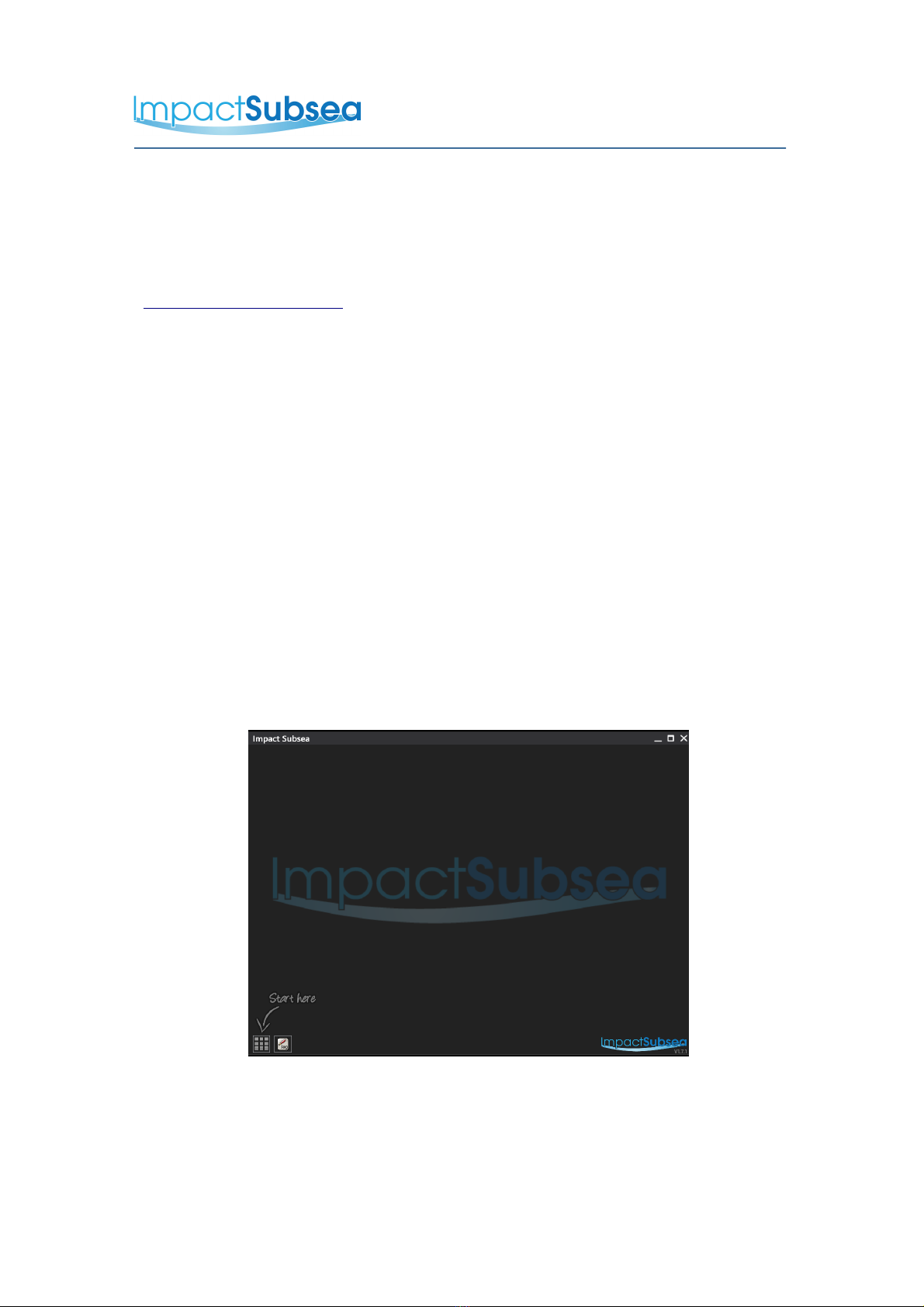
6.1 Establishing Communications with the ISD4000
Step 1:
Run the Impact Subsea software. When run for the first time, you will be presented
with the following screen:
Start Screen
© Impact Subsea Ltd
13
www.impactsubsea.com
www.impactsubsea.comwww.impactsubsea.com
www.impactsubsea.com
Innovative Underwater Products
Innovative Underwater ProductsInnovative Underwater Products
Innovative Underwater Products
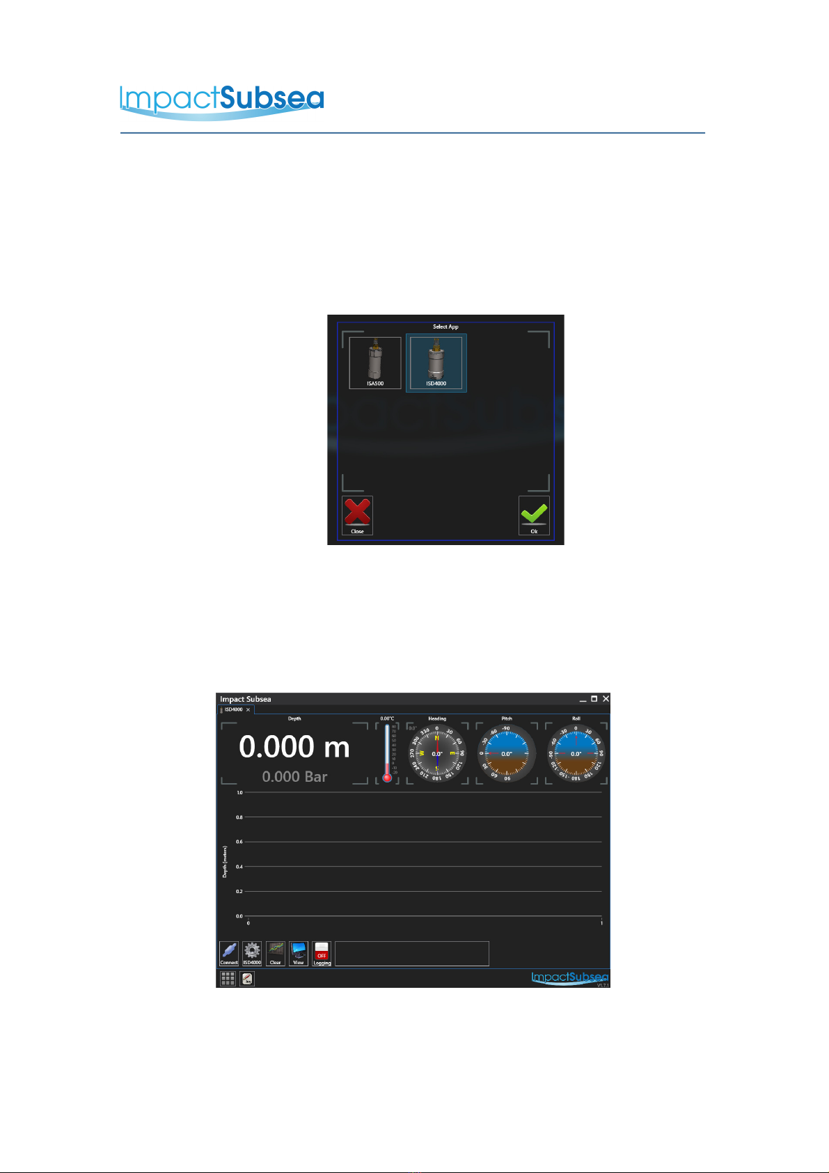
Step 2:
Click on the Apps button at the lower left hand side of the window. This has a 'Start
here' arrow pointing to it.
This will present you with the option of selecting the appropriate App for your
sensor. Choose 'ISD4000' and click on 'Ok':
Select App Screen
Step 3:
You will now be presented with the ISD4000 user interface. In order to connect to
your ISD4000 unit, please click on the 'Connect' button at the lower left hand side of
the screen:
ISD4000 User Interface
© Impact Subsea Ltd
14

www.impactsubsea.com
www.impactsubsea.comwww.impactsubsea.com
www.impactsubsea.com
Innovative Underwater Products
Innovative Underwater ProductsInnovative Underwater Products
Innovative Underwater Products
Step 4:
Having pressed the 'Connect' button, you will be presented with the following
screen:
Connect Screen
Set the Comm Port which you have connected the ISD4000 to. Ensure that the
baudrate set matches that printed in the 'Comms' area of the ISD4000 label.
Click on the slider which reads 'PORT CLOSED' to open the port.
Assuming all wiring is correct & the ISD4000 has power, the software will now
communicate with the ISD4000 unit.
6.2 Configuring the ISD4000
With the software connected to the ISD4000 the unit can be configured and
calibrated using the 'ISD4000' settings button:
ISD4000 Settings Button
Clicking the above button will take you to the settings page:
© Impact Subsea Ltd
15
www.impactsubsea.com
www.impactsubsea.comwww.impactsubsea.com
www.impactsubsea.com
Innovative Underwater Products
Innovative Underwater ProductsInnovative Underwater Products
Innovative Underwater Products
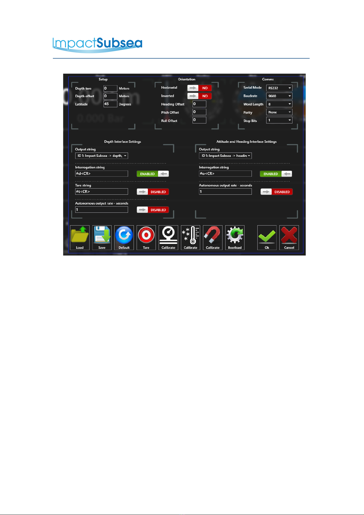
ISD4000 Settings Page
This settings page allows a number of options to be set.
6.2.1 Setup
Depth tare, depth offset and the latitude of operation can be entered
here
6.2.2 Orientation
This section is useful for ISD4000 units supplied with the HMRU
option. This allows the unit to be informed if it has been mounted
horizontally or inverted (with pressure port facing upwards).
Heading, Pitch and Roll offsets can also be entered here.
6.2.3 Comms
By default the ISD4000 is set to RS232, 9600, N81. The unit can be
configured to operate in RS232 or RS485 using all standard baud
rates. The required communications setup of the ISD4000 can be
configured here.
© Impact Subsea Ltd
16

www.impactsubsea.com
www.impactsubsea.comwww.impactsubsea.com
www.impactsubsea.com
Innovative Underwater Products
Innovative Underwater ProductsInnovative Underwater Products
Innovative Underwater Products
6.2.4 Depth Interface Settings
This section allows the required depth/temperature serial output string
to be set. If you require a specific string not listed, please contact
Impact Subsea Support to discuss your requirements.
If required, a custom interrogation string can be entered here.
Interrogation capability can also be enabled/disabled.
A custom Tare string can also be entered together with the enabling
and disabling of this feature. Please note, that a tare function can be
performed at any time & depth. Whenever this is performed, the
depth output from the unit will be tared to the depth/pressure at that
time.
If the unit is required to output data continuously, this can be enabled
here. The autonomous output rate can also be set at any value up to
100Hz.
6.2.5 Attitude and Heading Interface Settings
This section allows the required Attitude and Heading serial output
string to be set (where the ISD4000 has been supplied with integrated
HMRU).
A custom interrogation string can be entered here.
If the unit is required to output data continuously, this can be enabled
here. The autonomous output rate can also be set at any value up to
100Hz.
6.2.6 Load
Pre-saved settings can be loaded into the software for quick setup of
the ISD4000.
6.2.7 Save
This function will save all the ISD4000 settings to a file in a location of
your choice. This is a ideal method of creating a backup of preferred
settings.
© Impact Subsea Ltd
17

www.impactsubsea.com
www.impactsubsea.comwww.impactsubsea.com
www.impactsubsea.com
Innovative Underwater Products
Innovative Underwater ProductsInnovative Underwater Products
Innovative Underwater Products
6.2.8 Default
The default button will populate all of the settings with the default
configuration values. Please note, this will also set the
communications of the unit to default settings – RS232, 9600, N81.
6.2.9 Tare
This button will tare the unit to zero.
6.2.10 Calibrate (Gauge Logo)
This button will initiate the pressure calibration procedure. The
software will talk you through calibrating the pressure sensor within
the ISD4000 unit.
6.2.11 Calibrate (Thermometer Logo)
This button will initiate the temperature calibration procedure. The
software will talk you through calibrating the temperature sensor within
the ISD4000 unit.
6.2.12 Calibrate (Magnet Logo)
This button will initiate the Heading calibration procedure. The
calibration is to remove the effects of permanent hard and soft iron on
the heading. The software will talk you through the calibration
process.
6.2.13 Bootload
If you wish to update the firmware of the ISD4000 the bootload button
will allow a firmware file to be loaded onto the unit.
© Impact Subsea Ltd
18

www.impactsubsea.com
www.impactsubsea.comwww.impactsubsea.com
www.impactsubsea.com
Innovative Underwater Products
Innovative Underwater ProductsInnovative Underwater Products
Innovative Underwater Products
7.0 Servicing
The ISD4000 housing is Titanium, which is highly corrosion resistant. The unit is
intended to be exceptionally low maintenance.
On a regular basis, the pressure port should be checked and cleaned to ensure
salt/silt buildup is minimised.
Following deployment, remove the pressure sensor protective cap locking ring.
Once the ring is removed, the protective cap will slide off:
Rinse the pressure and temperature sensor in fresh water until clean. Avoid
physically touching the pressure diaphragm. Also avoid pulling on the temperature
probe – this is held in place by the protective cap. Should the diaphragm suffer
from physical damage, this will void the warranty of the ISD4000 unit:
After cleaning, place the protective cap back on the ISD4000 and secure in place
with the locking clip.
© Impact Subsea Ltd
19

www.impactsubsea.com
www.impactsubsea.comwww.impactsubsea.com
www.impactsubsea.com
Innovative Underwater Products
Innovative Underwater ProductsInnovative Underwater Products
Innovative Underwater Products
8.0 Warranty
The ISD4000 is supplied with a Limited Warranty. This warranty applies only to the
ISD4000 unit, and only if the ISD4000 is purchased from Impact Subsea Ltd.
What does the limited warranty cover?
This Limited Warranty covers any defects in material or workmanship under normal
use during the Warranty Period.
During the Warranty Period, Impact Subsea Ltd will repair or replace, at no charge,
products or part of a product that prove defective because of improper material or
workmanship under normal use and maintenance.
What will we do to correct the problems?
Impact Subsea Ltd will either replace or repair the Product at no charge, using new
or refurbished replacement parts. Replacement or repair is at the discretion of
Impact Subsea Ltd.
How long does the coverage last?
The Warranty Period for the ISD4000, purchased from Impact Subsea Ltd, is 1 year
from the date of dispatch from Impact Subsea Ltd.
A replacement ISD4000, or part assumes the remaining warranty of the original
ISD4000 or 60 days from the replacement or repair, whichever is longer.
What does this limited warranty not cover?
This limited warranty does not cover any problem that is caused by conditions,
malfunctions or damage not resulting from the defects in material or workmanship.
What do you have to do?
To obtain a warranty repair of your ISD4000 unit, you must first contact Impact
Subsea Support to determine the problem and the most appropriate solution for
you.
© Impact Subsea Ltd
20
Other manuals for ISD4000
2
Table of contents
Other Impact Subsea Accessories manuals


