Impact Subsea ISA500 User manual
www.impactsubsea.com
www.impactsubsea.comwww.impactsubsea.com
www.impactsubsea.com
Innovative Underwater Products
Innovative Underwater ProductsInnovative Underwater Products
Innovative Underwater Products
ISA500
Altitude, Pitch, Roll &
Heading Sensor
Installation & Operation
Manual
Revision: 1.1
Date: 07/10/2015
Impact Subsea Ltd
T. +44 (0) 1224 460 850
E. info impactsubsea.co.uk
W. www.impactsubsea.com

Contents
1.0 Introduction.................................................................................................................................3
2.0 Specification................................................................................................................................4
2.1 Unit Overview..................................................................................................................4
2.2 Unit Dimensions..............................................................................................................4
2.3 Acoustic, Heading, Attitude & Temperature....................................................................5
2.4 Communications, Power & Physical...............................................................................5
3.0 Overview.....................................................................................................................................6
4.0 Installation .............................................................................................................................7
4.1 Location............................................................................................................................7
4.1.1 Acoustics (For Maximising Altitude Measurement Performance)........................7
4.1.2 Magnetic Disturbers (For Maximising Heading Performance).............................7
4.1.3 Alignment with Vehicle (For Maximising Pitch/Roll Accuracy)..........................8
4.1.4 Heat Sources (For Maximising Temperature Accuracy).......................................8
4.2 Mounting .........................................................................................................................9
4.3 Electrical Installation.....................................................................................................10
4.3.1 Connector Pin Out..............................................................................................10
4.3.2 Connector Mating...............................................................................................11
4.3.3 Connector Cleaning............................................................................................11
5.0 Software & Configuration.........................................................................................................12
ISA500 Page......................................................................................................................................17
6.0 Maintenance...............................................................................................................................26
7.0 Theory Of Operation..................................................................................................................27
7.1 Altitude - Basic Principles...............................................................................................27
7.2 The Sonar Equation........................................................................................................29
7.2.1 Source Level (SL)............................................................................................29
7.2.2 Transmission Loss (TL)....................................................................................30
7.2.3 Noise Level (NL)..............................................................................................30
7.2.4 Directional Index (DI)......................................................................................31
7.2.5 Detection Threshold (DT)................................................................................31
7.3 Heading, Pitch & Roll..................................................................................................32
7.4 Temperature..................................................................................................................32
8.0 Warranty....................................................................................................................................33
9.0 Technical Support .....................................................................................................................34
Every effort is made to ensure that information within this document is up to date. However, information within this
document is subject to change without notice, in-line with our commitment to continuous product development and
improvement.
www.impactsubsea.com
www.impactsubsea.comwww.impactsubsea.com
www.impactsubsea.com
Innovative Underwater Products
Innovative Underwater ProductsInnovative Underwater Products
Innovative Underwater Products
1.0 Introduction
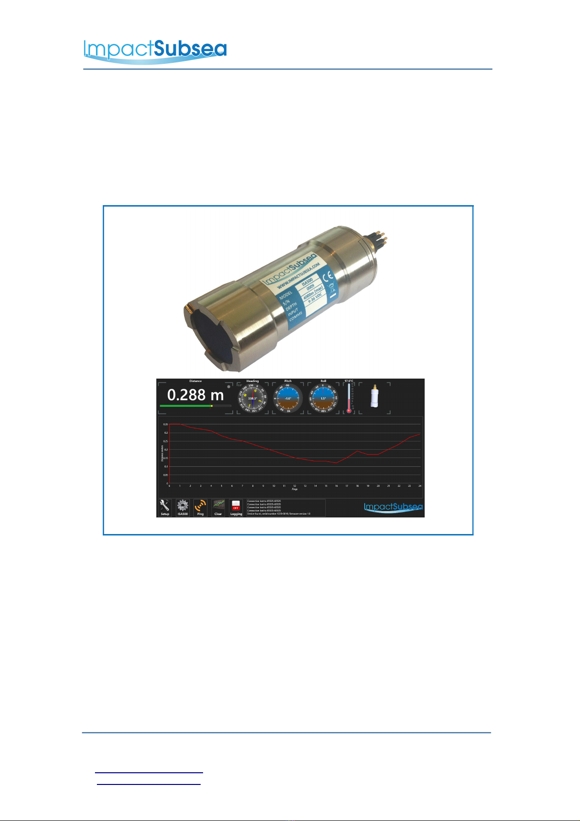
The ISA500 provides exceptionally long range Altitude measurement, Heading,
Pitch, Roll and Temperature readings.
Utilising a broadband composite transducer and advanced digital signal processing
techniques; enables the ISA500 to achieve long range capability with a high degree
of accuracy and stability.
The availability of heading, pitch and roll provides the capability to clearly
understand the orientation of the unit at all times. This can also be used to auto-
correct slant range readings; providing a true altitude measurement if required.
Alternatively these sensor readings can be used for navigation purposes of a
ROV or AUV.
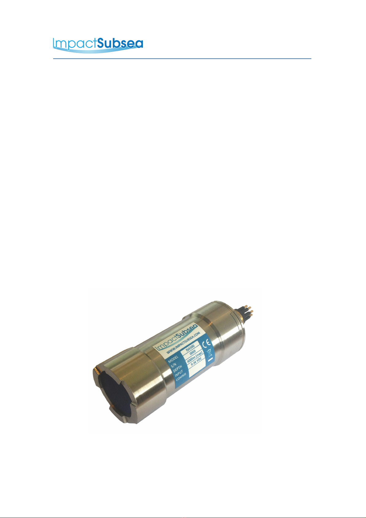
Housed in a compact, lightweight titanium housing ensures that the ISA500 is not
only at the forefront of sensor technology, but is built to withstand the most extreme
underwater environments.
The above capabilities make the ISA500 the Altimeter, Heading and Motion
Reference Unit of choice for numerous underwater applications.
ISA500 Altimeter
© Impact Subsea Ltd
3
www.impactsubsea.com
www.impactsubsea.comwww.impactsubsea.com
www.impactsubsea.com
Innovative Underwater Products
Innovative Underwater ProductsInnovative Underwater Products
Innovative Underwater Products
2.0 Specification
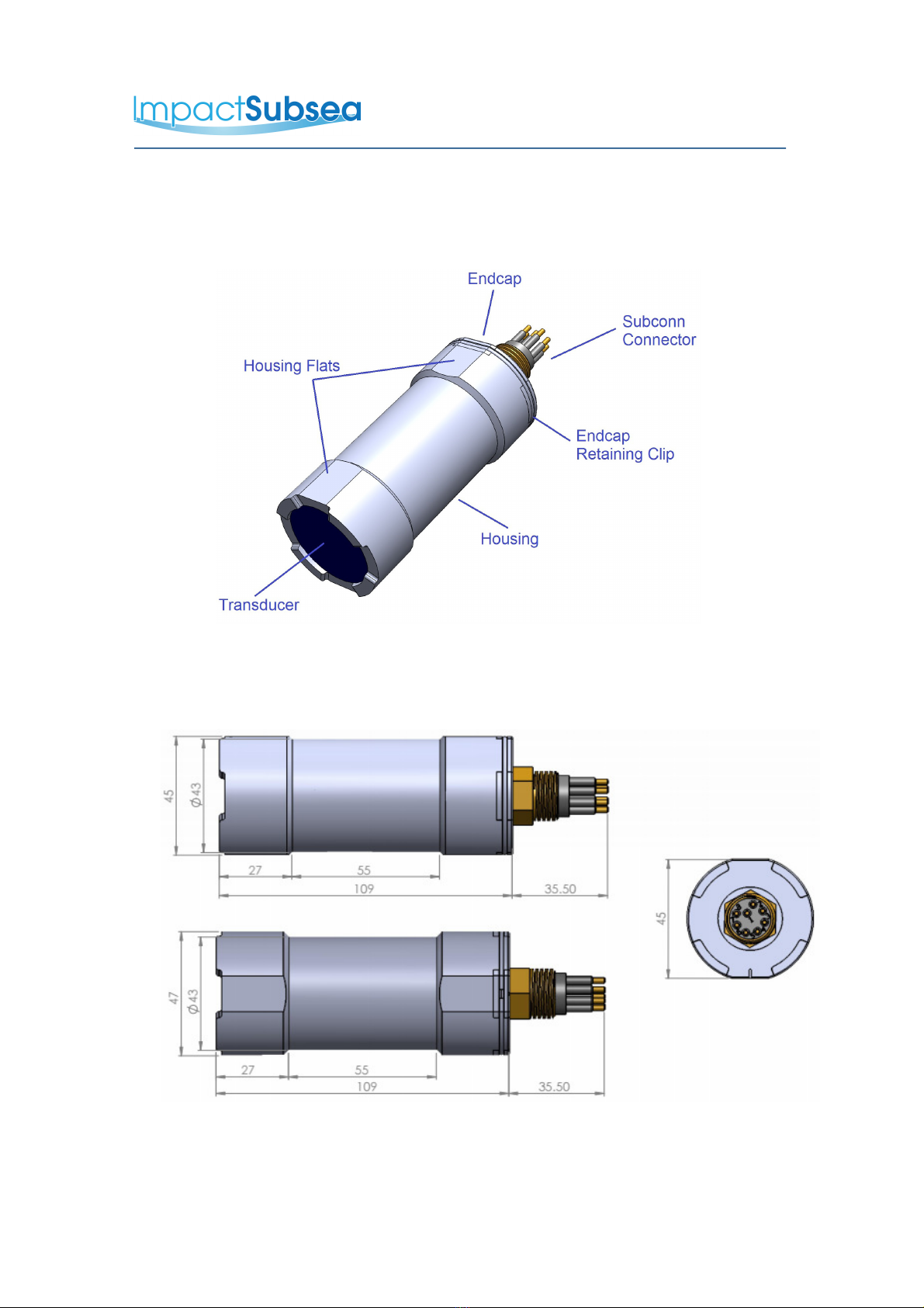
2.1 Unit Overview
2.2 Unit Dimensions
All dimensions are in mm.
© Impact Subsea Ltd
4
www.impactsubsea.com
www.impactsubsea.comwww.impactsubsea.com
www.impactsubsea.com
Innovative Underwater Products
Innovative Underwater ProductsInnovative Underwater Products
Innovative Underwater Products
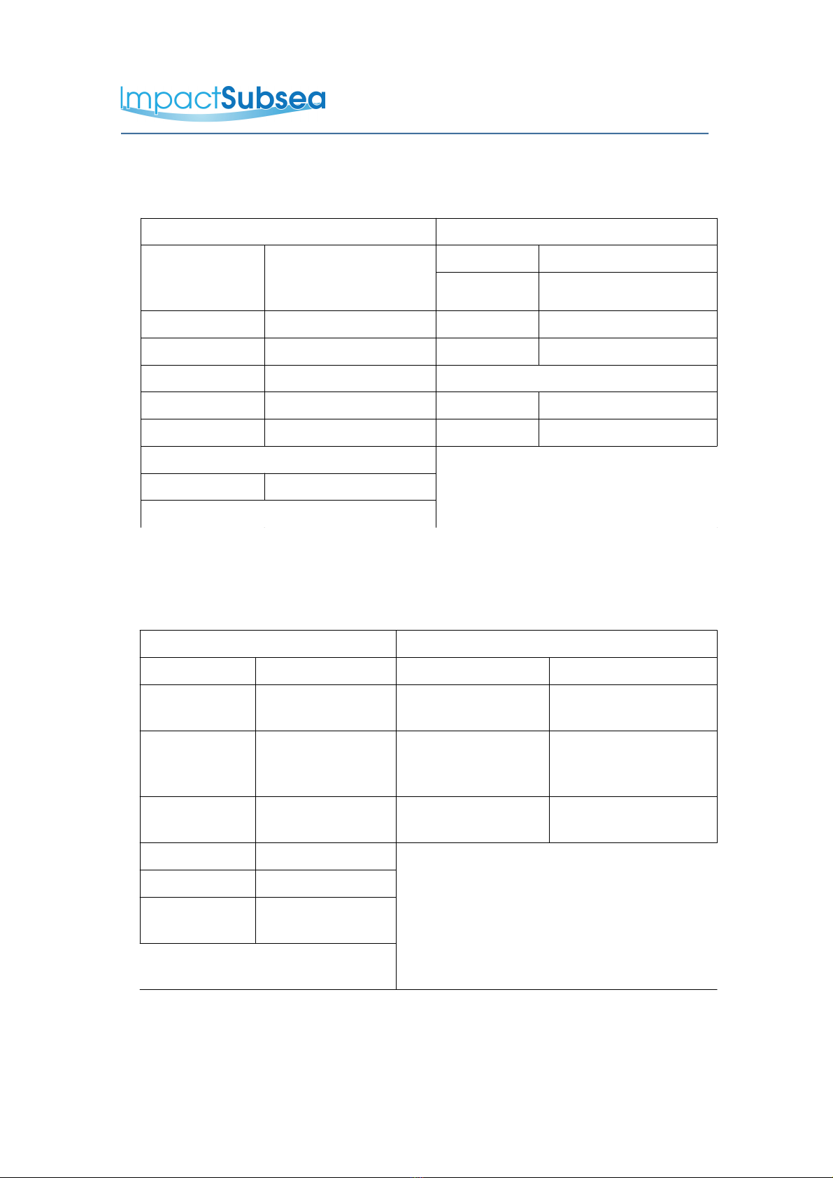
2.3 Acoustic, Heading, Attitude & Temperature
Acoustic Attitude
Frequency 500kHz Standard
(400 to 600kHz
Selectable)
Pitch Range ± 90°
Roll Range ± 180°
Range 0.1 to 120m Accuracy 0.2°
Resolution 0.75mm Resolution 0.1°
Beam Angle 6°conical at 500kHz Temperature
Signalling Monotonic Accuracy 0.5°
Pulse Length Auto/User Defined Resolution 0.1°
Heading
Accuracy ± 1°
Resolution 0.1°
2.4 Communications, Power & Physical
Communications & Power Physical
Digital RS232 & RS485 Weight (Air/Water) 0.5 / 0.325 kg
Protocol 4800 to 115200
baud
Depth Rating 4,000m
Analogue 0 to 5 V DC or
0 to 10V DC or
4-20mA
Temperature Operating: -10 to 40°
Storage: -20 to 50°
Data Continuous or on
demand
Connector Subconn MCBH8M-
SS fitted as standard
Data Rate Up to 10Hz
* 100% Tx power, 10Hz update rate
Input Voltage 9 to 36V DC
Power (No
Altitude)
25mA @ 24V DC
Power (With
Altitude)
51mA @ 24V DC
*
© Impact Subsea Ltd
5
www.impactsubsea.com
www.impactsubsea.comwww.impactsubsea.com
www.impactsubsea.com
Innovative Underwater Products
Innovative Underwater ProductsInnovative Underwater Products
Innovative Underwater Products
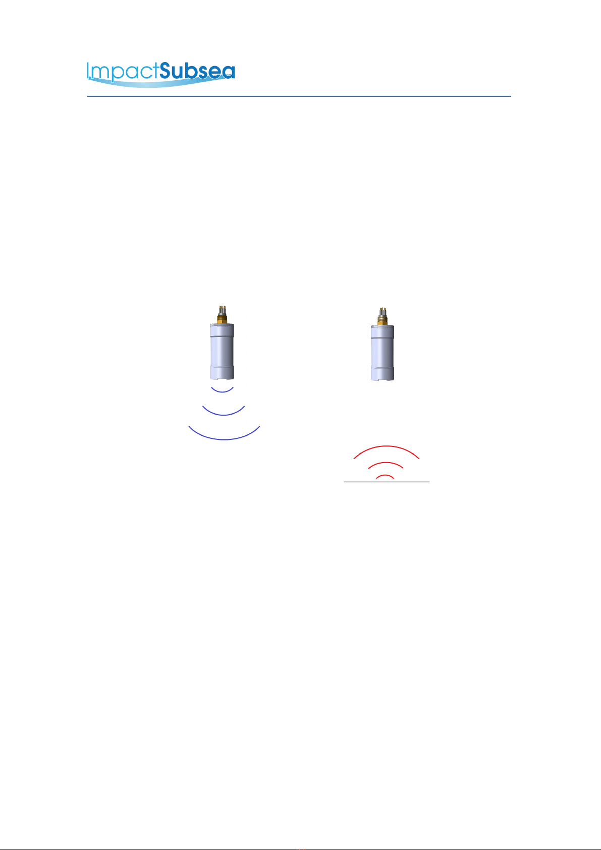
3.0 Overview
The ISA500 is a hydro-acoustic device – making use of acoustics in water to achieve
range measurement. It is important to note that the device is designed to provide
range/altitude measurements in water, and will not provide such readings when
operated in air.
For calculating altitude, the principle of operation is simple. The ISA500 emits an
acoustic pulse, which passes through the water column (Diagram 1). On impact with
the seabed, a proportion of this acoustic wave is reflected back towards the ISA500
(Diagram 2).
Diagram 1 Diagram 2
The ISA500 times how long the acoustic wave takes to travel from the ISA500, to the
seabed and back again.
With this time value, combined with a knowledge of the speed of sound in water, the
distance/altitude can be calculated.
The Heading, Pitch and Roll readings are provided by a Micro-Electro-Mechanical
system (MEMS) within the unit.
The temperature reading comes from a dedicated temperature sensor, located in the
connector end cap.
For a detailed overview of the theory of operation, please see Section 8.
© Impact Subsea Ltd
6

www.impactsubsea.com
www.impactsubsea.comwww.impactsubsea.com
www.impactsubsea.com
Innovative Underwater Products
Innovative Underwater ProductsInnovative Underwater Products
Innovative Underwater Products
4.0 Installation
4.1 Location
When evaluating the installation location of the ISA500, there are several
factors to consider to achieve optimum operation from each part of the
ISA500:
–
Acoustics (Altitude Measurement)
–
Magnetic Disturbers (Heading)
–
Alignment with Vehicle (Pitch/Roll)
–
Heat Sources (Temperature Measurement)
4.1.1 Acoustics (For Maximising Altitude Measurement Performance)
The transducer must have a clear view of the seabed. Any items which
obstruct this view may result in erroneous Altitude measurements. If entirely
obstructed, no Altitude readings will be possible.
Ideally the ISA500 should not be operated in close proximity to other acoustic
equipment with the same operational frequency (500kHz). Other acoustic
equipment may cause the ISA500 to produce erratic Altitude readings.
In some instances, if the ISA500 is found to be causing interference with
other acoustic systems, the operational frequency can be adjusted to move it
out of band with the other equipment – see Section 5 for details.
4.1.2 Magnetic Disturbers (For Maximising Heading Performance)
Where the heading output is to be used, the ISA500 should be mounted as
far as possible from sources of magnetic interference.
Electrical items which can cause magnetic interference include motors,
transformers and valve packs. Ferrous metals, or any other
magnetically active materials will also have influence on the heading reading.
Thus, where possible, the unit should be installed as far as possible from
magnetically active materials.
© Impact Subsea Ltd
7
www.impactsubsea.com
www.impactsubsea.comwww.impactsubsea.com
www.impactsubsea.com
Innovative Underwater Products
Innovative Underwater ProductsInnovative Underwater Products
Innovative Underwater Products
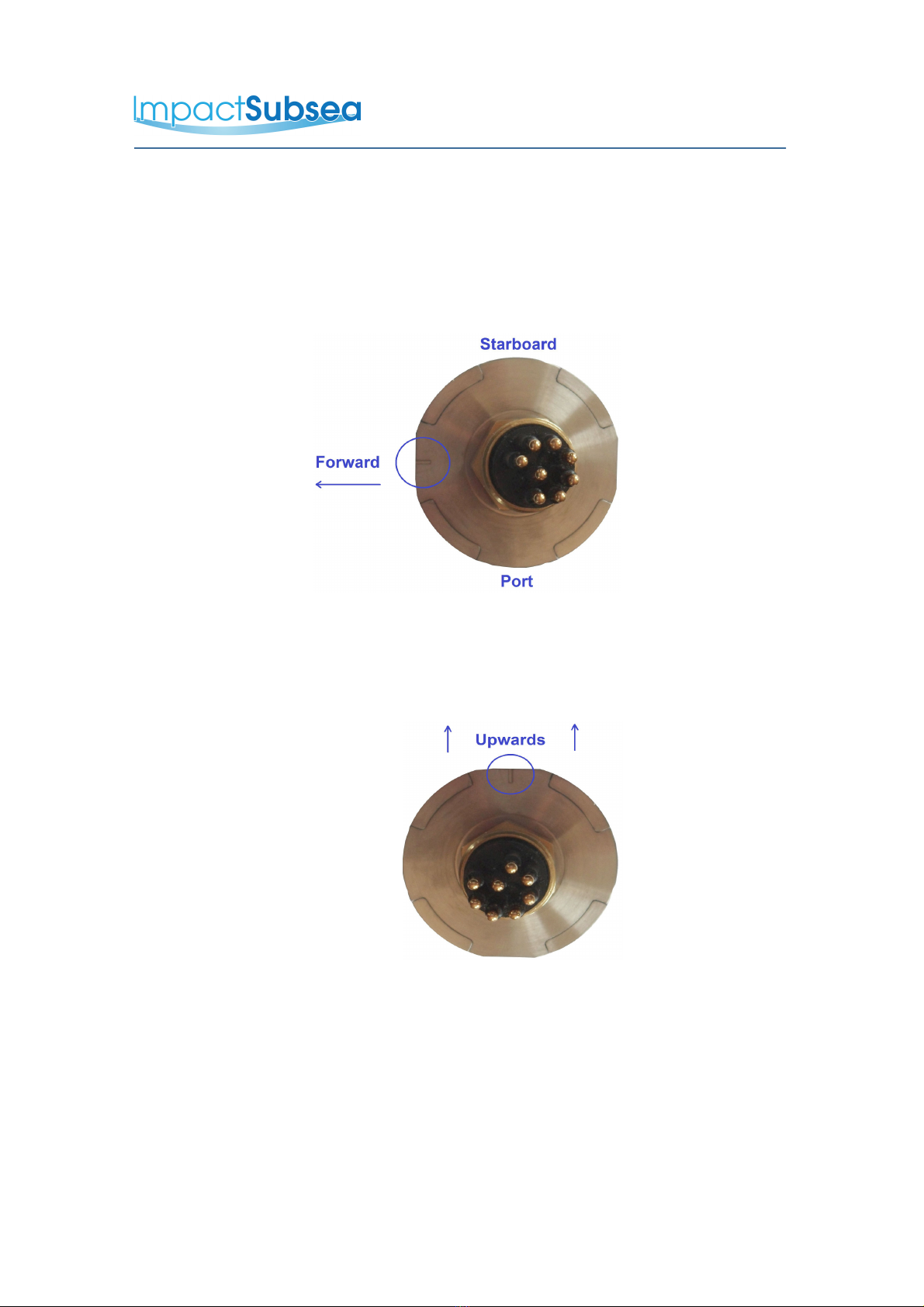
4.1.3 Alignment with Vehicle (For Maximising Pitch/Roll Accuracy)
When mounting vertically, the ISA500 should be mounted with the
transducer facing downwards (to the seabed) and the indentation in the
connector end cap pointing forwards, in the direction of forward vehicle
travel:
When mounting horizontally (for horizontal range measurements) the
ISA500 should be mounted with the transducer facing in the direction of
measurement to be made, with the indentation in the connector end cap
pointing upwards:
4.1.4 Heat Sources (For Maximising Temperature Accuracy)
In order for the ISA500 to read the ambient temperature of the water, it
should not be installed in close proximity of any heat sources (such as
Hydraulic Power Packs).
© Impact Subsea Ltd
8

www.impactsubsea.com
www.impactsubsea.comwww.impactsubsea.com
www.impactsubsea.com
Innovative Underwater Products
Innovative Underwater ProductsInnovative Underwater Products
Innovative Underwater Products
4.2 Mounting
The ISA500 should be mounted using clamps around the mid section of the
body. The unit has a 55mm recess in the main body to enable a clamp to be
tightened securely around the unit:
Ideally a non-metallic clamp should be used, however in the event that this is
not possible, effort should be made to electrically isolate the clamp from the
ISA500 housing. This can be achieved by using rubber or plastic strips
around the body of the ISA500.
If the unit is not isolated, corrosion of the ISA500, the clamp or surrounding
metal may be observed. In long term installations this could provide a flood
risk to the ISA500 due to housing degradation, resulting in a loss of water
sealing capability.
The ISA500 has two flats, on either side of the body – these are to enable the
unit to sit tightly against another flat surface if available. These flats also help
prevent the unit moving when on the workbench for testing.
© Impact Subsea Ltd
9
www.impactsubsea.com
www.impactsubsea.comwww.impactsubsea.com
www.impactsubsea.com
Innovative Underwater Products
Innovative Underwater ProductsInnovative Underwater Products
Innovative Underwater Products
4.3 Electrical Installation
The ISA500 is fitted with a SubConn MCBH8M-SS connector as standard.
This will mate to a SubConn MCIL8F connector/cable assembly.
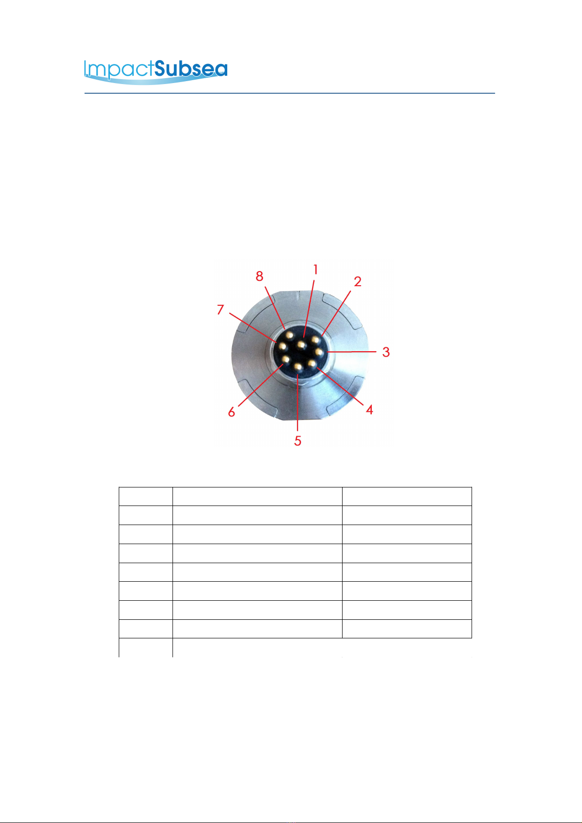
4.3.1 Connector Pin Out
The standard connector pin out is provided below:
Male Connector on ISA500 Unit
Pin Function Mating Wire Colour
1 0VDC Black
2 9-36VDC White
3 Analogue Out Red
4 0V Analogue Green
5 0V Digital Orange
6 Trigger Blue
7 RS232 TX & RS485 A+ White/Black
8 RS232 RX & RS485 B- Red/Black
© Impact Subsea Ltd
10

www.impactsubsea.com
www.impactsubsea.comwww.impactsubsea.com
www.impactsubsea.com
Innovative Underwater Products
Innovative Underwater ProductsInnovative Underwater Products
Innovative Underwater Products
4.3.2 Connector Mating
When mating the cable to the SubConn connector, to maximise the life of the
connector, it is important to observe the following:
–
Always apply grease before mating. Molykote 44 Medium grease must be
used.
–
Disconnect by pulling straight, not at an angle.
–
Do not pull on the cable and avoid sharp bends at cable entry.
–
Do not over-tighten the bulkhead nut.
Do not expose the connector to extended periods of heat or direct sunlight. If
a connector becomes very dry, it should be soaked in fresh water before use
4.3.3 Connector Cleaning
General cleaning and removal of any accumulated sand or mud on a
connector should be performed using spray based cleaner (for example
Isopropyl Alcohol).
New grease must be applied again prior to mating.
© Impact Subsea Ltd
11

www.impactsubsea.com
www.impactsubsea.comwww.impactsubsea.com
www.impactsubsea.com
Innovative Underwater Products
Innovative Underwater ProductsInnovative Underwater Products
Innovative Underwater Products
5.0 Software & Configuration
The ISA500 is supplied with its own bespoke software package, which can either be
used to operate the unit or can purely be used to configure the unit to output a
specific string.
5.1Minimum System Requirement
The ISA500 software package requires Microsoft .net 4.5 framework or higher.
This is included with windows 8 and above. Windows Vista and 7 require a
update available from the Microsoft website. Windows XP will not run the
ISA500 software .net frameworks above version 3.5.1 so isn't comparable with
the ISA500 software.
A minimum screen resolution of 1366 x 768 is required to display all parts of the
user interface fully.
The computer should have a minimum of 100MB of free hard drive space, and
at least 2GB of RAM.
5.2 Main User Interface
Upon opening the ISA500 application, you will be presented with the following
screen:
ISA500 Software Main Screen
© Impact Subsea Ltd
12
www.impactsubsea.com
www.impactsubsea.comwww.impactsubsea.com
www.impactsubsea.com
Innovative Underwater Products
Innovative Underwater ProductsInnovative Underwater Products
Innovative Underwater Products
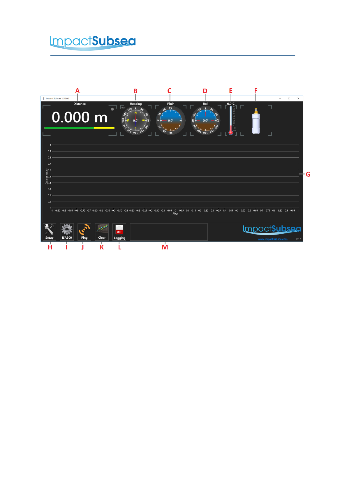
Each of the core user interface components are highlighted in the below image, and
described in the following text:
A - Distance
This provides the distance which has been read from the ISA500 transducer to the
target. In the majority of applications this distance is the Altitude (assuming the
ISA500 transducer is pointing towards the seabed).
B - Heading
This is the Heading value, referenced to the indentation on the ISA500 connector
end cap. This will provide heading to the local magnetic north value.
C - Pitch & D - Roll
These two dials display the Pitch and Roll of the ISA500.
E - Temperature
The temperature sensor is thermally bonded to the end cap. The displayed
temperature may slightly lag changes in environmental temperature due to the
thermal mass of the end cap.
© Impact Subsea Ltd
13

www.impactsubsea.com
www.impactsubsea.comwww.impactsubsea.com
www.impactsubsea.com
Innovative Underwater Products
Innovative Underwater ProductsInnovative Underwater Products
Innovative Underwater Products
F - Model
The model of the ISA500 mirrors the orientation of the unit.
G - Graph
This displays a plot of measurements points against range. The x-axis represents
the ping number with the y-axis representing range in meters.
The graphs y-axis dynamically scales automatically based on the upper and lower
displayed readings. This provides the greatest level of detail.
H - Setup
This is the button to access all of the settings for the topside computer. This is
where you go first to setup your computer's Com port to talk to the ISA500.
This button also provides access to the Log file setup. This allows you to set
where log files are saved, and also what is saved in them.
I - ISA500
This button will open a settings page for the ISA500. This page contains all
configurable options of the unit, and should be used to setup the ISA500 to operate
exactly as you require it. This page should be accessed after having established
communications via the 'Setup' button.
J- Ping
This button will instruct the ISA500 to emit a single ping. The range reading from
this ping will be shown in the 'Distance' box on the interface. The value of this ping
will also be plotted on the graph.
K - Clear
This button will clear the graph.
L- Logging
This button will turn logging on or off. To configure a log file, this is done under the
'Setup' button.
© Impact Subsea Ltd
14
www.impactsubsea.com
www.impactsubsea.comwww.impactsubsea.com
www.impactsubsea.com
Innovative Underwater Products
Innovative Underwater ProductsInnovative Underwater Products
Innovative Underwater Products
M - Status
This area shows any status messages from the ISA500. Upon startup/initial
connection to the ISA500 the connected unit's serial number will be shown.
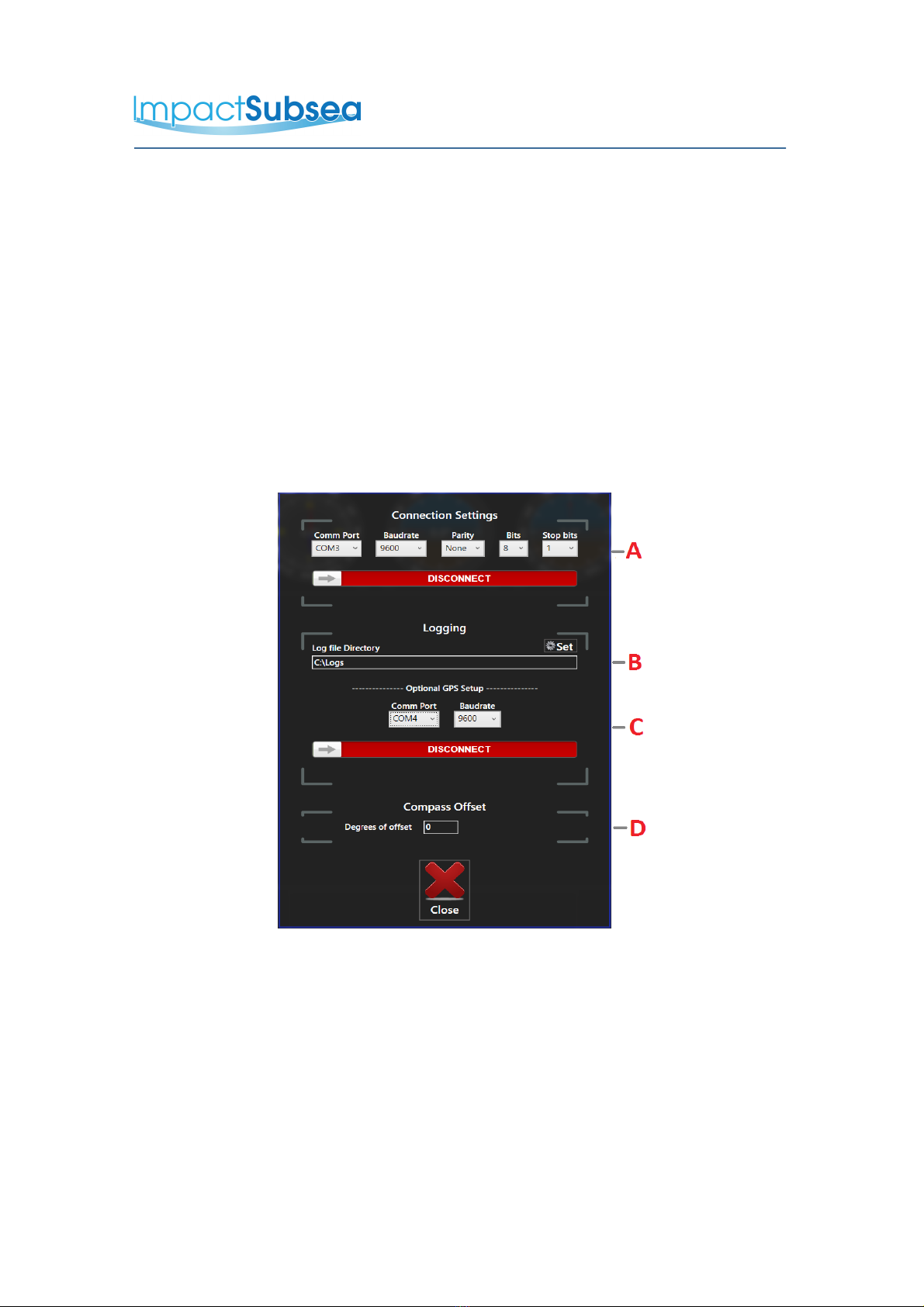
5.3 Setup
Setup is the first place to start – to establish communications between the ISA500
and your computer running the software.
Upon clicking the 'Setup' icon, the following window will be displayed:
A – Comms Settings
These are the communication settings for the PC and should match how the ISA500
is configured. The connect / disconnect switch opens / closes the com port and
searches for the ISA500.
© Impact Subsea Ltd
15

www.impactsubsea.com
www.impactsubsea.comwww.impactsubsea.com
www.impactsubsea.com
Innovative Underwater Products
Innovative Underwater ProductsInnovative Underwater Products
Innovative Underwater Products
The default communication settings for the ISA500 are:
Baud rate: 9600
Parity: none
Data bits: 8
stop bits: 1
If you are unable to determine the communication of the ISA500, please follow
these steps:
1. Set the baud rate of the software to 9,600 baud
2. Power on the Altimeter
3. Rotate the ISA500 to have the transducer facing upwards
4. Rotate the ISA500 to have the transducer facing downwards
5. Repeat steps 3 & 4 three times
Your ISA500 is now set to communicate at 9,600 baud, RS232. The unit will
return to its previous baud rate/comms setting after power cycle.
B - Logging
This is the directory where any log files will be stored. This can be adjusted to suit
your preferred log location.
C - GPS
Should you wish to log GPS co-ordinates along with the altitude readings, the
Comm Port and Baud rate of your GPS receiver can be set here. The GPS must
output standard NMEA GPGGA strings in-order for the software to log longitude and
latitude.
D - Compass Offset
The ISA500 provides heading to the local magnetic north. If you are aware of the
difference between magnetic north and true north in your area of operation and
offset can be entered here. This will allow the ISA500 software to display a True
North Heading.
© Impact Subsea Ltd
16

www.impactsubsea.com
www.impactsubsea.comwww.impactsubsea.com
www.impactsubsea.com
Innovative Underwater Products
Innovative Underwater ProductsInnovative Underwater Products
Innovative Underwater Products
5.4 ISA500
Clicking on the ISA500 button will take you to the units settings page, to setup and
configure the ISA500 to operate as required.
Typically the ISA500 will be supplied by Impact Subsea pre-set for your application.
Thus settings within this window should only be changed if you wish to alter some
functionality of the unit.
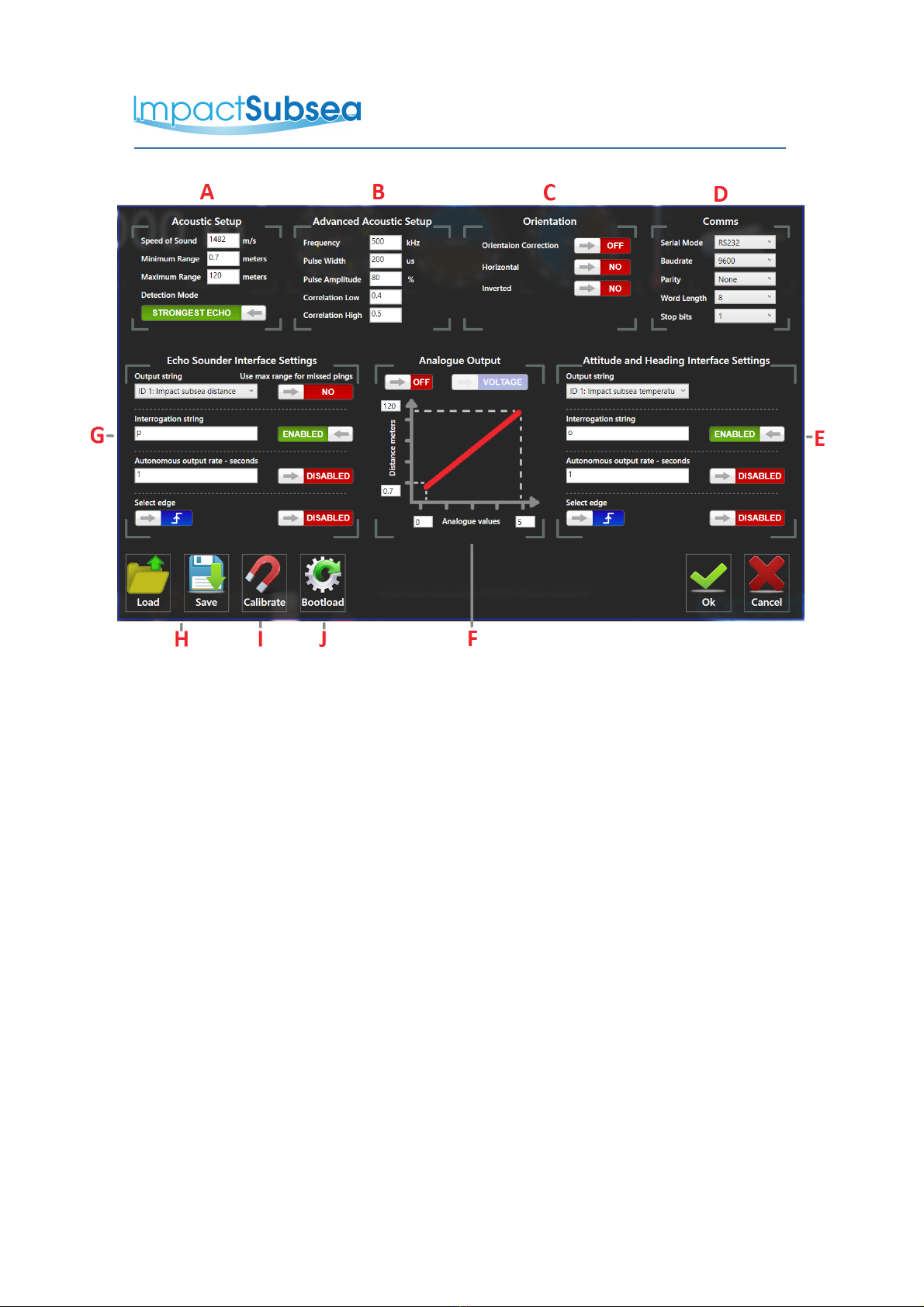
On clicking the ISA500 button, you will be presented with the following page:
ISA500 Page
Each of the components of the ISA500 page are highlighted in the following image
and each described in turn thereafter:
© Impact Subsea Ltd
17
www.impactsubsea.com
www.impactsubsea.comwww.impactsubsea.com
www.impactsubsea.com
Innovative Underwater Products
Innovative Underwater ProductsInnovative Underwater Products
Innovative Underwater Products
A - Acoustic Setup
Each of the settings in this box allow the basic acoustic configuration of the ISA500
to be set:
Speed Of Sound
This is the speed of sound in water/liquid which the ISA500 is operating in. By default the
unit is set to 1482 meters per second. This is the typical speed of sound in fresh water. If
operating the unit in seawater, or other liquid a more accurate speed of sound can be
entered.
An accurate speed of sound is essential to ensure accuracy of Altitude measurement.
Minimum Range
This is the minimum range the ISA500 will detect down to. By default, this is set to 0.7
meters.
If operating the ISA500 with a long range setting (such as 120 meters), 0.7m minimum range
will ensure that the transmit pulse is not inadvertently detected as a return echo.
If the pulse width/maximum range is reduced (down to say 50 meters, at 50 microseconds
pulse width, the ISA500 will measure down to 0.10 meter or below.
© Impact Subsea Ltd
18

www.impactsubsea.com
www.impactsubsea.comwww.impactsubsea.com
www.impactsubsea.com
Innovative Underwater Products
Innovative Underwater ProductsInnovative Underwater Products
Innovative Underwater Products
Maximum Range
This is the maximum range the ISA500 will detect. By default this is set to 120 meters.
If you are working in shallow water, or conducting short range measurements, this value can
be decreased to the maximum range you wish to detect. This can be useful to increase the
update rate of the ISA500 if required (due to a longer time required to wait for a ping to
return from 120m as opposed to say 50 meters.
Detection Mode
This is the method by which the ISA500 will detect a returning echo. There are two detection
modes available: First Echo and Strongest Echo.
In First Echo detection mode, the ISA500 will base its Altitude measurement on the first
return echo which it correlates.
In Strongest Echo, the ISA500 will listen to all returned echoes up to the maximum range. It
will then use the strongest Echo out of them all and use this to calculate Altitude.
B - Advanced Acoustic Setup
Each of the settings in this box allow the configuration of the ISA500 advanced
acoustic settings to be made:
Frequency
The ISA500 is adjustable to operate anywhere from 400kHz to 600kHz. The
transducer, together with hardware and detection algorithms have all been designed
to provide this wide bandwidth capability.
By default the unit is set to operate at 500kHz, but can be adjusted to fit in with other
acoustic devices, or for specific applications.
Pulse Width
The pulse width is the length in time that each 'ping' made by the ISA500 lasts. By
default this is 200 microseconds. This is an ideal length to achieve maximum range
capability. For short range applications, it may be advantageous to reduce this value
to allow very close measurements to be made.
Pulse Amplitude
This is the power which the transmitted pulse has. By default this is set to 80%,
which will achieve maximum range capability in most applications.
For tank tests, or areas where multi-path reflections are an issue, it may be
advantageous to reduce this. For example, to measure in a test tank environment, a
5% amplitude is often sufficient.
© Impact Subsea Ltd
19

www.impactsubsea.com
www.impactsubsea.comwww.impactsubsea.com
www.impactsubsea.com
Innovative Underwater Products
Innovative Underwater ProductsInnovative Underwater Products
Innovative Underwater Products
Correlation Low & Correlation High
The ISA500 has a advanced correlator which it uses to detect a returned echo.
By default the low and high values are set to 0.4 and 0.5. These values are found to
be optimum for the majority of cases and should not be altered.
The values are left here, so that they can be adjusted under the guidance of Impact
Subsea technical support, should you specific application require it.
C - Orientation
Orientation Correction
Orientation correction turns on and off the automatic compensation for pitch and roll on the
Altitude reading. With this value set to Off, the ISA500 will purely provide range
measurements. With this value turned On, the ISA500 will provide a true Altitude value,
regardless of the Pitch and Roll of the unit.
The correction may not be exact, due to many factors, however it will be significantly more
accurate than a pure range reading.
D - Comms
The Comms box allows you to setup the communications protocol used by the
ISA500.
Baudrate
The baudrate dropdown box allows for selection of all standard baud rate values.
Serial Mode
The serial mode button allows selection between RS232 or RS485 serial communications.
E - Attitude and Heading Interface Settings
This box allows for the configuration of the Attitude and Heading string from the
ISA500.
Output String
This box allows selection of the output strings available from your ISA500 unit. If you require
a particular string which is not present, please contact Impact Subsea support to have this
added. The string selected will be output either by interrogation or autonomously –
depending on the following settings:
Interrogation String & Enable/Disable
Within the 'Interrogation String' box, you can enter a letter of your choice. When the ISA500
receives this letter, it will return the string which has been selected in the 'Output String' box.
The enable/disable button will either disable or enable interrogation capability.
© Impact Subsea Ltd
20
Other manuals for ISA500
1
Table of contents
Other Impact Subsea Accessories manuals


Popular Accessories manuals by other brands


S+S Regeltechnik
S+S Regeltechnik AERASGARD KLQ-CO2 Operating Instructions, Mounting & Installation

Eurotops
Eurotops EP543 Introduction manual

Bebecar
Bebecar 51480 quick start guide

Sony
Sony B Mechanizm Operation manual

Elkay
Elkay EWTLA8*1D Series Installation, care & use manual

Venstar
Venstar ACC0401 specification


