Impact Subsea ISM3D User manual

www.impactsubsea.com
Innovative Underwater Products
ISM3D
Heading, Pitch & Roll Sensor
Installation & Operation
Manual
Revision: 1.2
Date: 09/01/19
Impact Subsea Ltd
T. +44 (0) 1224 460 850
E. info@impactsubsea.co.uk
W. www.impactsubsea.com

Contents
1.0 Introduction.................................................................................................................................3
2.0 Specification................................................................................................................................4
2.1 Unit Overview .................................................................................................................4
2.2 Unit Dimensions..............................................................................................................4
2.3 Attitude & Heading Reference System............................................................................5
2.4 Communications, Power & Physical...............................................................................5
3.0 Overview.....................................................................................................................................6
4.0 Installation .............................................................................................................................7
4.1 Location............................................................................................................................7
4.1.1 Magnetic Disturbers (For Heading Accuracy).....................................................7
4.1.2 Alignment with Vehicle (For Pitch/Roll Accuracy)...............................................7
4.2 Mounting .........................................................................................................................9
4.3 Electrical .......................................................................................................................10
4.3.1 Connector Pin Out..............................................................................................10
4.3.2 Power..................................................................................................................11
4.3.3 Serial Interface....................................................................................................11
4.3.4 RS232 Wiring.....................................................................................................11
4.3.5 RS485 Wiring.....................................................................................................12
4.3.6 Establishing Communications............................................................................13
4.3.7 Connector Mating...............................................................................................13
4.3.8 Connector Cleaning............................................................................................13
5.0 Operation ..................................................................................................................................14
5.1 Use With seaView Software...........................................................................................14
5.2 Integration With Systems...............................................................................................15
5.3 ISM3D Setup..................................................................................................................15
5.4 Magnetic Calibration......................................................................................................18
6.0 ASCII Output Strings ...............................................................................................................23
6.1 AHRS.............................................................................................................................23
7.0 Servicing....................................................................................................................................26
8.0 Warranty....................................................................................................................................27
9.0 Technical Support .....................................................................................................................28
Every effort is made to ensure that information within this document is up to date. However, information within this
document is subject to change without notice, in-line with our commitment to continuous product development and
improvement.

www.impactsubsea.com
Innovative Underwater Products
1.0 Introduction
The ISM3D sensor is a compact and highly accurate Attitude and Heading
Reference System providing Heading, Pitch & Roll.
Suitable for a large range of underwater applications, the ISM3D can be used with
ROVs, AUVs, Hydro-graphic Survey, Construction, Positioning and any other
application where accurate Heading, Pitch & Roll is required underwater.
The Heading, Pitch and Roll readings are provided from integrated Micro Electro
Mechanical Systems (MEMS) based Magnetometers, Accelerometers and
Gyroscopes. The outputs of each MEMs based device are fused together to provide
highly accurate and stable Heading, Pitch and Roll measurements.
Using the Inertial Heading mode, the ISM3D also provides a high resilience against
temporary magnetic interferers. This enables successful prolonged operation
alongside steel structures where required.
Housed in a compact and lightweight Titanium or Delrin® housing ensures that the
ISM3D is not only at the forefront of sensor technology; but is built to withstand the
most extreme underwater environments.
ISM3D Attitude & Heading Reference System (Titanium)
© Impact Subsea Ltd 3
www.impactsubsea.com
Innovative Underwater Products
2.0 Specification
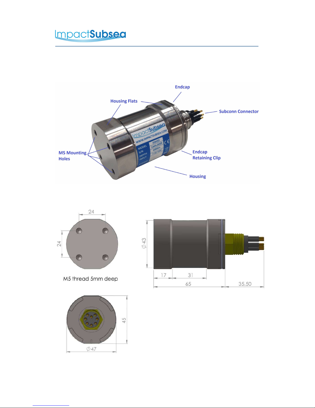
2.1 Unit Overview
2.2 Unit Dimensions
All dimensions are in mm.
© Impact Subsea Ltd 4

www.impactsubsea.com
Innovative Underwater Products
2.3 Attitude & Heading Reference System
Heading Attitude
Accuracy ± 0.5° of Magnetic
North
Pitch ± 90°
Roll ± 180°
Resolution 0.01° Accuracy ± 0.07°
Resolution 0.01°
2.4 Communications, Power & Physical
Communications & Power Physical
Digital RS232 & RS485 Weight
(Air/Water)
Titanium: 0.33/ 0.225kg
Delrin: 0.20 / 0.10kg
Protocol 300 to 115,200
baud
Depth Rating Titanium: 6,000 meters
Delrin: 1,000 meters
Data Continuous or on
demand
Temperature Operating: -10 to 50°
Storage: -20 to 70°
Data Rate Up to 250Hz Connector Subconn MCBH8M-SS
fitted as standard
Input Voltage 7 to 32V DC
Power 29mA @ 24V DC
© Impact Subsea Ltd 5

www.impactsubsea.com
Innovative Underwater Products
3.0 Overview
The ISM3D is a highly compact, robust and accurate underwater Attitude & Heading
Reference System (AHRS).
The ISM3D is depth rated to 1,000 meters (Delrin®) or 6,000 meters (Titanium).
The Heading, Pitch and Roll readings are provided by a Micro-Electro-Mechanical
system (MEMS) based technology. MEMs based Gyros, Accelerometers and
Magnetometers are integrated within the unit.
The outputs from each MEMS based sensor are processed by an advanced fusion
algorithm to provide highly stable and accurate Heading, Pitch & Roll.
For optimal heading performance, a hard and soft iron calibration can be performed
on the unit once installed on the ROV, AUV or other underwater platform. This
ensures that a consistently accurate heading is provided at all times.
In areas where a large amount of steel or other magnetic disturber is present, the unit
can be switched to Inertial mode. Inertial mode operates using the Angular Rate
Gyroscopes and Accelerometers, without input from the Magnetometer. The low drift
rate of the MEMS based Gyroscopes enables navigation to be conducted in areas
where previously only a fibre or ring laser diode based heading sensor would suffice.
The ISM3D can be configured using the supplied seaView software. seaView allows
all settings to be configured (output strings, communications protocol, baud rate etc).
In addition to allowing the ISM3D to be configured, seaView also allows all outputs to
be viewed in real time and logged.
© Impact Subsea Ltd 6

www.impactsubsea.com
Innovative Underwater Products
4.0 Installation
4.1 Location
When evaluating the installation location of the ISM3D, there are several
factors to consider to achieve optimum operation from each part of the
unit:
–Magnetic Disturbers (Heading)
–Alignment with Vehicle (Pitch/Roll)
4.1.1 Magnetic Disturbers (For Heading Accuracy)
Where the heading output is to be used, the ISM3D should be mounted as
far as possible from sources of magnetic interference.
Electrical items which can cause magnetic interference include motors,
transformers and valve packs.
Ferrous metals, or any other magnetically active materials will also have
influence on the heading reading. Thus, where possible, the unit should be
installed as far as possible from magnetically active materials.
A magnetic calibration should be conducted using the seaView software once
the unit is physically installed.
4.1.2 Alignment with Vehicle (For Pitch/Roll Accuracy)
When mounting vertically, the ISM3D should be mounted with the
base (complete with mounting screw holes) facing downwards (to the
seabed) and the indentation in the connector end cap pointing forwards, in
the direction of forward vehicle travel:
© Impact Subsea Ltd 7

www.impactsubsea.com
Innovative Underwater Products
When mounting horizontally the ISM3D should be installed with the
indentation in the connector end cap pointing upwards:
© Impact Subsea Ltd 8
www.impactsubsea.com
Innovative Underwater Products
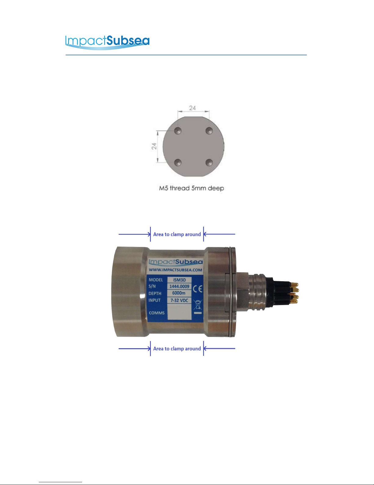
4.2 Mounting
The ISM3D should be mounted using four M5 Screws, screwed into the base
of the unit:
Alternatively the unit has a 31mm recess in the main body to enable a
clamp to be tightened securely around the unit:
Ideally a non-metallic clamp should be used, however in the event that this is
not possible, effort should be made to electrically isolate the clamp from the
ISM3D housing. This can be achieved by using rubber or plastic strips
around the body of the ISM3D.
The ISM3D has two flats, on either side of the body – these are to enable
the unit to sit tightly against another flat surface if available.
© Impact Subsea Ltd 9
www.impactsubsea.com
Innovative Underwater Products
4.3 Electrical
The ISM3D is fitted with a SubConn MCBH8M-SS connector as standard.
This will mate to a SubConn MCIL8F connector/cable assembly.
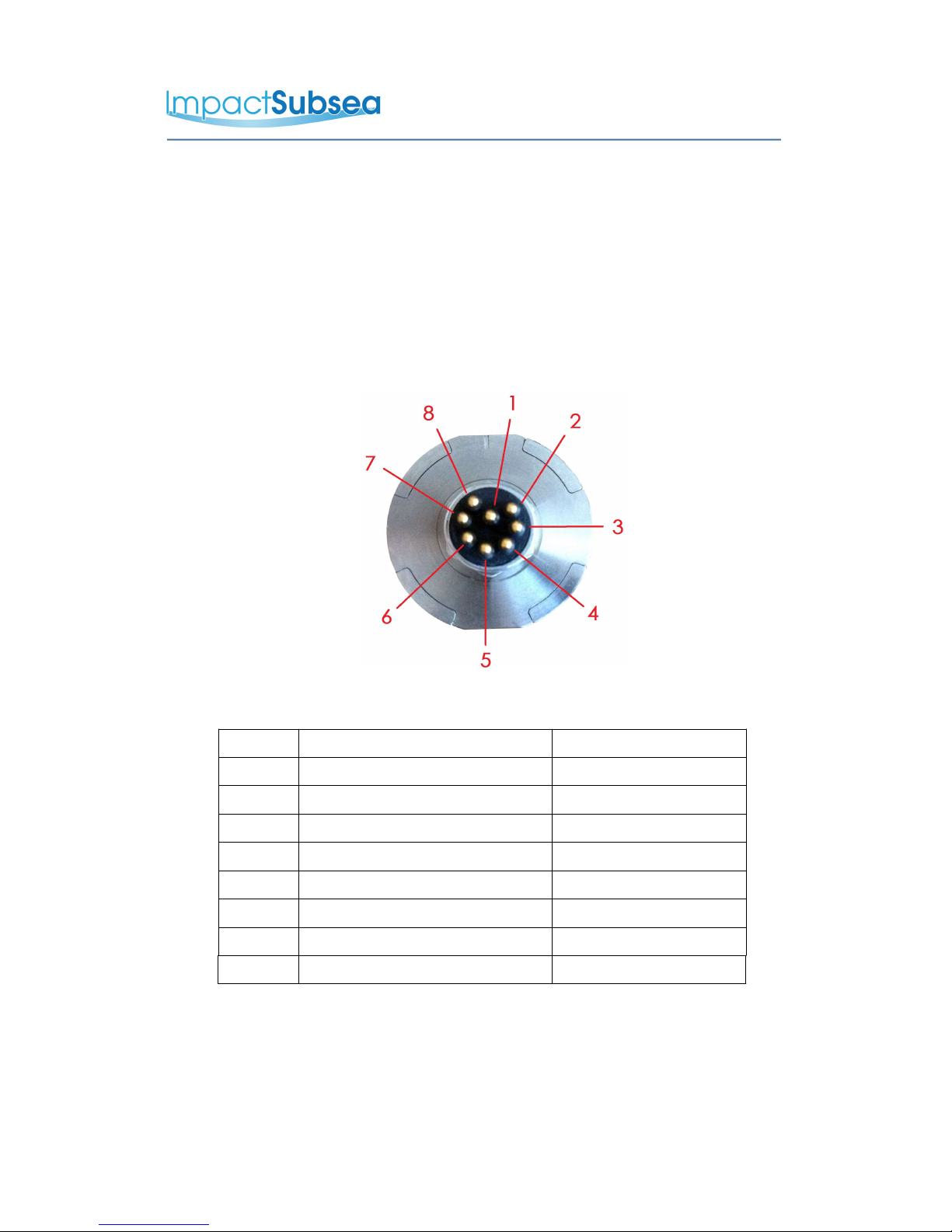
4.3.1 Connector Pin Out
The standard connector pin out is provided below:
Male Connector on ISM3D Unit
Pin Function Mating Wire Colour
1 0VDC Black
2 7-32VDC White
3 Not Used Red
4 Not Used Green
5 0V Digital Orange
6 Not Used Blue
7 RS232 TX & RS485 A+ White/Black
8 RS232 RX & RS485 B- Red/Black
© Impact Subsea Ltd 10

www.impactsubsea.com
Innovative Underwater Products
4.3.2 Power
The ISM3D is polarity protected and fused with a 400mA resettable poly
fuse. Internal circuitry isolates the supply from the outside environment
requiring the serial interface to use the digital 0V reference pin.
4.3.3 Serial Interface
The RS232 and RS485 interface is isolated from the supply and has in-line
fused protection on the serial lines. A prolonged transient voltage on these
lines will blow the surface mount fuses which will require replacement by
Impact Subsea or an approved distributor.
4.3.4 RS232 Wiring
© Impact Subsea Ltd 11
www.impactsubsea.com
Innovative Underwater Products
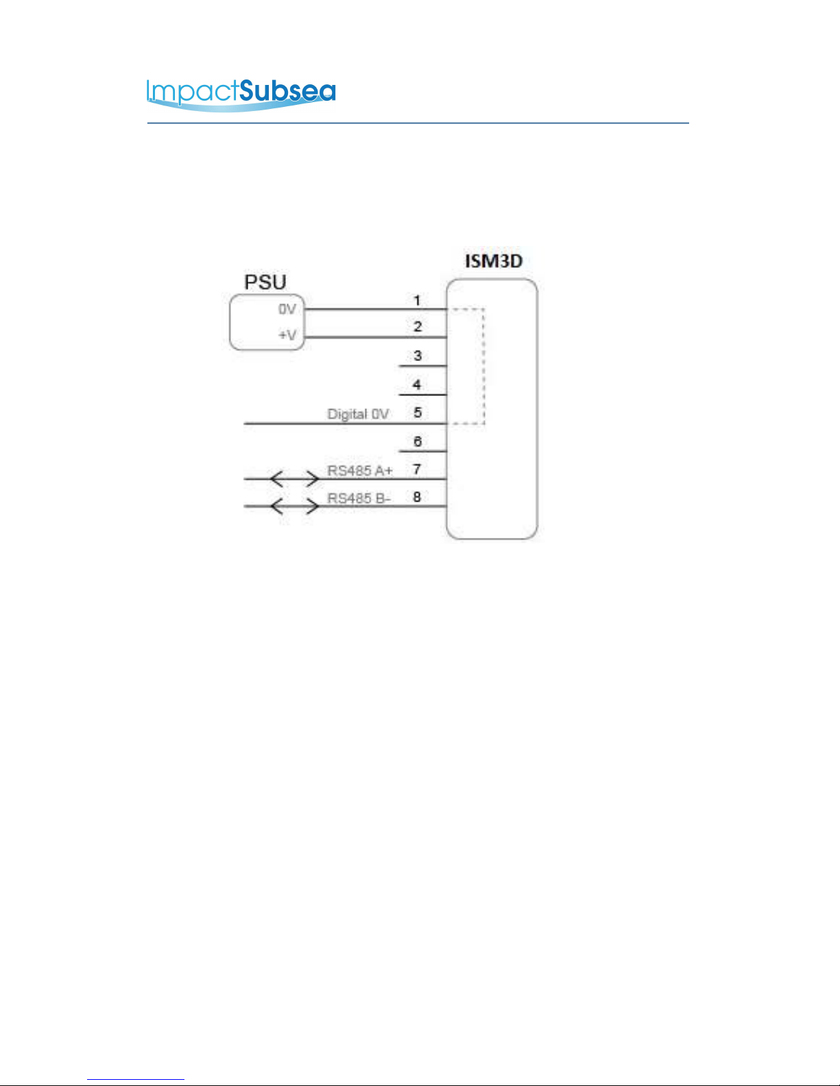
4.3.5 RS485 Wiring
The RS485 termination resistor is software selectable.
The digital 0V must be connected on an RS485 interfaces, otherwise
the voltage potential between one of the A+ or B- lines to ground could
reach a damaging level
© Impact Subsea Ltd 12
www.impactsubsea.com
Innovative Underwater Products
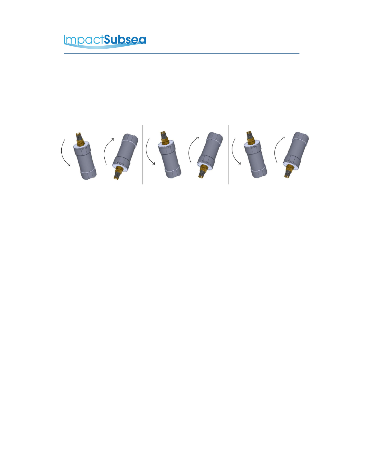
4.3.6 Establishing Communications
The default serial settings are RS232, 9600, N81
If the ISM3D is tilted from vertical to upside down 3 times within the first 10
seconds of power up then it will temporarily configure the serial interface to
the default and output an ASCII message with the settings.
Note: When the device is powered cycled the serial interface setting will
revert back to the last configuration.
4.3.7 Connector Mating
When mating the cable to the SubConn connector, to maximise the life of the
connector, it is important to observe the following:
–Always apply grease before mating. Molykote 44 Medium grease must be
used.
–Disconnect by pulling straight, not at an angle.
–Do not pull on the cable and avoid sharp bends at cable entry.
–Do not over-tighten the bulkhead nut.
Do not expose the connector to extended periods of heat or direct sunlight. If
a connector becomes very dry, it should be soaked in fresh water before use
4.3.8 Connector Cleaning
General cleaning and removal of any accumulated sand or mud on a
connector should be performed using spray based cleaner (for example
Isopropyl Alcohol).
New grease must be applied again prior to mating.
© Impact Subsea Ltd 13

www.impactsubsea.com
Innovative Underwater Products
5.0 Operation
5.1 Use With seaView Software
The ISM3D is supplied with the highly intuitive seaView software.
The latest version of seaView can be downloaded from
www.impactsubsea.com
seaView can be used with all Impact Subsea sensors. Single sensors can be
operated, or multiple sensors together.
seaView is designed for use with a PC running the Windows 7, 8 or 10
operating system and requires Microsoft's .net framework 4.5.2 or above to
be installed.
seaView uses an advance framed binary protocol to communicate to the
ISM3D and can do so over RS232 or RS485 at any standard baud rate.
The parity must be none, stop bits 1 and data bits 8. If the ISM3D
communication settings differ from this then perform the comms
reset as described in the 'Establishing Communications' section of this
manual.
All settings and offsets are saved to the ISM3D device flash memory.
Impact Subsea seaView Software
© Impact Subsea Ltd 14

www.impactsubsea.com
Innovative Underwater Products
5.2 Integration With Systems
Conceptually there are two modes of operation, Interrogated and
Autonomous.
Integration mode requires a master to request the ISM3D to make a
measurement and report this back.
The ISM3D can be interrogated by the user defined interrogation string.
Upon interrogation the ISM3D will make a measurement and report back
the result over the serial interface.
Autonomous mode will make a measurement and output the results at a
specified time interval.
The ISM3D can be configured to operate in one or both of these modes at
the same time.
5.3 ISM3D Setup
The ISM3D unit can be configured to output a variety of output strings,
at various output rates, autonomously or by interrogation.
Offsets can be applied to the Heading, Pitch & Roll, the reference point for
Pitch, Roll & Heading can be changed and Inertial Mode can be enabled and
disabled.
All settings can be viewed and adjusted by using the Impact Subsea seaView
software. To alter settings, the ISM3D application should be run and the
settings page opened.
Clicking the green tick 'Save' button at any time will save the configured
settings to the ISM3D firmware. These settings will then be held until the
ISM3D is next configured using the seaView software.
© Impact Subsea Ltd 15

www.impactsubsea.com
Innovative Underwater Products
5.3.1 Communication Protocol
The Serial Mode can be adjusted (RS232, RS485 or RS458 Terminated).
The baud rate, word length, parity and stop bits can also be adjusted to suit interface requirements.
5.3.2 ISM3D Setup
The second setup page allows configuration of the output string, which mode the ISM3D should work in
along with various offsets:
The settings on each line (1 to 4) shown above are detailed:
© Impact Subsea Ltd 16

www.impactsubsea.com
Innovative Underwater Products
Line 1:
Allows for the selection of the required output string:
Line 2:
Allows autonomous mode to be enabled and disabled. When enabled, the rate at which the output string
(defined in line 1) is set in times per second (Hz).
Line 3
Allows for an interrogation string to be enabled and disabled. When enabled the interrogation string (which
is used to trigger the output defined in line 1) can be configured to a command of the users choice. If this is
not altered, the default trigger command is #o<CR>.
Line 4
Allows an offset to be applied to the Heading, Pitch & Roll. If the difference between magnetic north and true
north is known, the offset can be applied here (either positive or negative degrees). This will enable the
ISM3D to report True North heading values.
Any inaccuracy in mounting (causing an offset to the pitch & roll) can be zero'd using the Pitch and Roll
offsets.
If the unit has been mounted Horizontally or Inverted, this can be set in the buttons of Line 4.
Line 4 also allows the Inertial Mode of the ISM3D to be enabled or disabled. The default and recommended
setting is to have the inertial mode enabled.
When inertial mode is enabled, the magnetometers are only used for the first ten seconds after power up to
find magnetic north. After ten seconds, the high grade MEMS Gyros take over as the primary heading
device and update the heading accordingly. In this mode the unit is highly resilient to magnetic interference
and can operate alongside sources of magnetic interference for several hours without significant drift in the
heading.
© Impact Subsea Ltd 17

www.impactsubsea.com
Innovative Underwater Products
5.4 Magnetic Calibration
Following final physical installation on the vehicle (or other structure) it is
critical that a magnetic calibration is conducted.
The magnetic calibration takes into account all local hard and soft iron
artefacts of the vehicle (or other structure the ISM3D is mounted to). This
enables the correction of any heading offsets that permanent magnetic
interferers may cause.
If the magnetic calibration is not conducted, the heading will not be
correct and will suffer from non linear movement when rotated. For example
when operating with inertial mode disabled, a 90° physical rotation may only
be recognised as a 80° rotation.
To conduct a good magnetic calibration, please complete the following
procedure. There is also a video demonstration of this procedure available
on the ISM3D product page of the Impact Subsea website.
5.4.1 Magnetic Calibration Procedure
Step1:
Ensure that the ISM3D has been physically installed in a location as free from magnetic interference as
possible (away from value packs, thrusters etc).
Step 2:
Check that the ISM3D is mounted securely to the structure ensuring the unit is not able to move
independently from the structure.
Step 3:
If conducting the magnetic calibration in a workshop, ideally hang the ROV from a crane away from magnetic
sources. If conducting the calibration at sea, deploy the ROV and move into open water, away from any
structures with a magnetic property (vessel, pipeline etc). Do not conduct the calibration with the ROV
on the vessel.
© Impact Subsea Ltd 18

www.impactsubsea.com
Innovative Underwater Products
Step 4:
Run the seaView software, select the ISM3D application and connect to the ISM3D unit:
Step 5:
Once connected to the ISM3D, go into the ISM3D settings (Gear Cog graphic)
Step 6:
Click on the 'Calibrate' button to open the calibration window:
© Impact Subsea Ltd 19
www.impactsubsea.com
Innovative Underwater Products
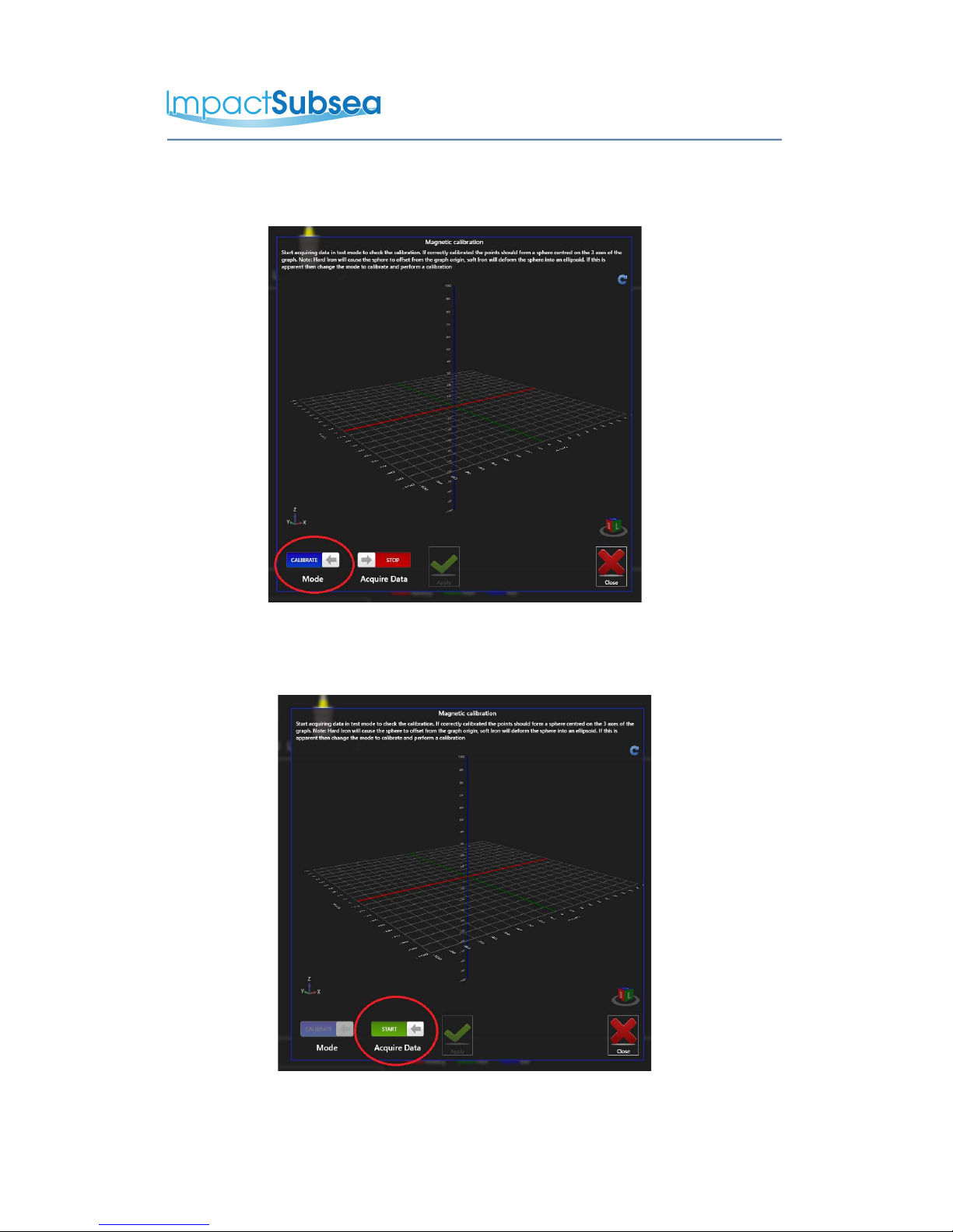
Step 7:
On the 'Mode' button, click this to change it to 'Calibrate'
Step 8:
On the 'Acquire Data' button change to 'Start'. The calibration process has now begun.
© Impact Subsea Ltd 20
Table of contents
Other Impact Subsea Accessories manuals


Popular Accessories manuals by other brands


aldes
aldes Agito and Presence Assembly instructions

iOptron
iOptron SmartStar 8600A quick start guide

Clas Ohlson
Clas Ohlson SCW-6002 user manual

Manitowoc
Manitowoc Q-1400 installation instructions

Dahua Technology
Dahua Technology Wireless Door Detector Plus user manual

Mobicool
Mobicool MCG15 operating manual