Impulse Yamuna Use and care manual

1
OPERATION- AND SAFETY
REGULATIONS
Yamuna

2
Contents
1
Description, application and working principle ............................................................................3
1.1 Description................................................................................................................................3
1.2 Construction of the pump unit................................................................................................3
1.3 Intended use..............................................................................................................................4
1.4 Unintended use.........................................................................................................................4
1.5 Specification and dimensions.................................................................................................5
2
Safety instruction .............................................................................................................................6
2.1 Warning stickers.......................................................................................................................6
3
Lifting instructions YAMUNA pump unit........................................................................................8
3.1 Moving the pump unit with a forklift.......................................................................................9
4
Pump unit installation....................................................................................................................10
4.1 Placement –general...............................................................................................................10
4.2 Outdoor use ............................................................................................................................11
4.3 Indoor use ...............................................................................................................................11
5
Daily maintenance of the pump ....................................................................................................12
6
Pump –general...............................................................................................................................14
6.1 Preparation for starting the pump unit.................................................................................14
6.2 To fill the pump housing with water:....................................................................................14
6.3 Pump –general...............................................................................................................................15
6.4 Preparations for starting........................................................................................................16
6.5 Priming fuel system ...............................................................................................................17
6.6 Stone catcher cleaning ..........................................................................................................18
7Control panel (type1)......................................................................................................................21
7.1 Starting type (1) ......................................................................................................................22
7.2 Stopping (type1) .....................................................................................................................23
8. Control panel (type2)......................................................................................................................25
8.1 Starting type (2) ......................................................................................................................25
8.2 Stopping (type2) .....................................................................................................................27
9. ECOMIZER-PRO (type3).................................................................................................................28
10. Monitoring during operation .........................................................................................................34
11. Draining the pump when there is danger of freezing .................................................................35
12. Troubleshooting table....................................................................................................................37

3
1
Description, application and working principle
1.1 Description
WARNING: This manual is intended to give Important Information that must be followed
during Storage, Transportation, Installation, Operation and Maintenance of the Pump-
Set. We therefore recommend that this manual is read carefully before the Pump-Set is
put into operation. To prevent damage being caused by inappropriate or incorrect use,
or by being used outside the normal operating parameters of the Pump-set, the
Instructions in this manual must be followed. Failure to do so may lead to damage to or
premature failure of the Pump-set and may cause Injury. Any such actions will invalidate
the warranty.
Impulse Yamuna pump is developed to pump clean to lightly polluted water with a maximum density
of 1,05 g/cm³ and a temperature between 0 and 45 degrees Celsius. Typical applications are:
- Horizontal drainage
- Vertical or Vacuum dewatering with dewatering filters.
- Remediation
- Installation of sewage systems
- Excavations
- Installation of piping
1.2 Construction of the pump unit
1.
Drive pulley
2.
Discharge
3.
Suction
4.
Stonecatcher
5.
Gearbox

4
1.3 Intended use
Piston pumps are only intended for pumping water from filters or drainage
hose(s), NOT for pumping dirty water drawn directly from the suction hose, with
or without a strainer.
Long fibres will cause immediate malfunctions. The maximum permissible particle size is 5
mm.
Contamination results in accelerated wear of the gland packing, gaskets, valve seals, cylinder
sleeves and piston cups.
1.4 Unintended use
−
It is not permitted to use the pump unit for pumping salt water.
−
It is not permitted to use the pump unit for pumping liquids containing larger suspendedsolids.
−
It is not permitted to use the pump unit for pumping flammable and/or explosive substances.
−
It is not permitted to deploy a standard pump unit in an environment in which there is a danger
of fire and/or explosion.
−
It is not permitted to deploy a standard pump unit in an ATEX environment.
−
Use the pump unit only for those applications listed on the specification sheet for the pump
unit.
−
It is not permitted to use the pump unit for any application and/or field of activity other than
that for which the pump unit was originally specified and installed without written permission
from Impulse.

5
1.5 Specification and dimensions
Pump specifications:
Type ..................................Yamuna
Max. flow .......................... 90 m3/hour
Max. pressure ................... 20 mwc
Max. suction lift ................. 9.5 mwc
Diesel engine .................... Hatz 1D81Z
Fuel consumption ............. Max. 0.8 L/hour
Connections ...................... 4"
Sound level ....................... Approx. 46 dB(A) at 10 m
Dry weight ......................... 1985 kg
Dimensions L x W x H ......... 2250 x 1050 x 1400 mm
Basic frame .......................... Hot dip galvanized
Doors ................................... 4 easy-access lockable doors
Fuel tank .............................. 230 ltr
Lifting points .......................... Fitted with single lifting point and forklift channels
Stackable ............................. Canopy is stackable
Exhaust system ................... Fully integrated in the canopy
Engine
Engine brand ....................... Hatz
Engine type .......................... 1D81Z
Power ................................... 5.5 kW
Max. engine speed .............. 1500 RPM
Fuel consumption ................ 245 g/kWh
Displacement ....................... 0.667 l
Number of cylinders ............. 1
Cooling system .................... Air cooled
Starting method ................... Electric start
Oil sump ............................... 4.5 ltr.

6
2
Safety instruction
This manual contains warning and safety symbols. Do not ignore the instructions. They are
provided for the benefit of your health and safety and to prevent damage to the environment and
the pump unit.
DANGER
When the danger symbol with the text DANGER is shown, it is accompanied by
information that is of great importance for the safety of everyone concerned.
Ignoring the information can result in injury (possibly severe) or evendeath.
WARNING
When the warning symbol with the text WARNING is shown, it is accompanied
by information that is of great importance for everyone concerned with the pump
unit. Ignoring the information can result in injury or damage (possibly severe) to
the pump
unit.
The pump unit conforms to the European Machinery Directive. However, this does not exclude the
possibility of accidents if used incorrectly.
Use of the pump for an application and/or deployment of the pump in an environment other than
defined at the time of purchase is strictly prohibited and can result in a hazardous situation.
This is particularly true for corrosive, toxic or other hazardous liquids. The pump unit may only be
installed, operated and maintained by persons who have received appropriate training and are
aware of the associated dangers.
The installer, operator and maintenance personnel must comply with the local safety regulations.
The company management is responsible for ensuring that all work is performed by qualified
personnel in a safe manner. It is not permitted to make changes to the pump unit without written
permission from Impulse.
If any changes are made to the pump without the written permission of Impulse, Impulse disclaims
all liability. Hearing protection must be worn if the noise emission level exceeds 85 dB(A).
Ensure that hot/cold and rotating parts of the pump are shielded adequately to prevent
unintentional contact.
It is not permitted to start the pump if such guards are missing or damaged.
The company management must ensure that everyone who works with/on the pump unit is aware
of the type of liquid that is being pumped. These persons must know what measures are to be
taken in the event of leakage.
Dispose of any liquids that have leaked, in a responsible manner. Observe local regulations
Never allow the pump unit to run with a blocked discharge line. The heat build-up could lead to an
explosion
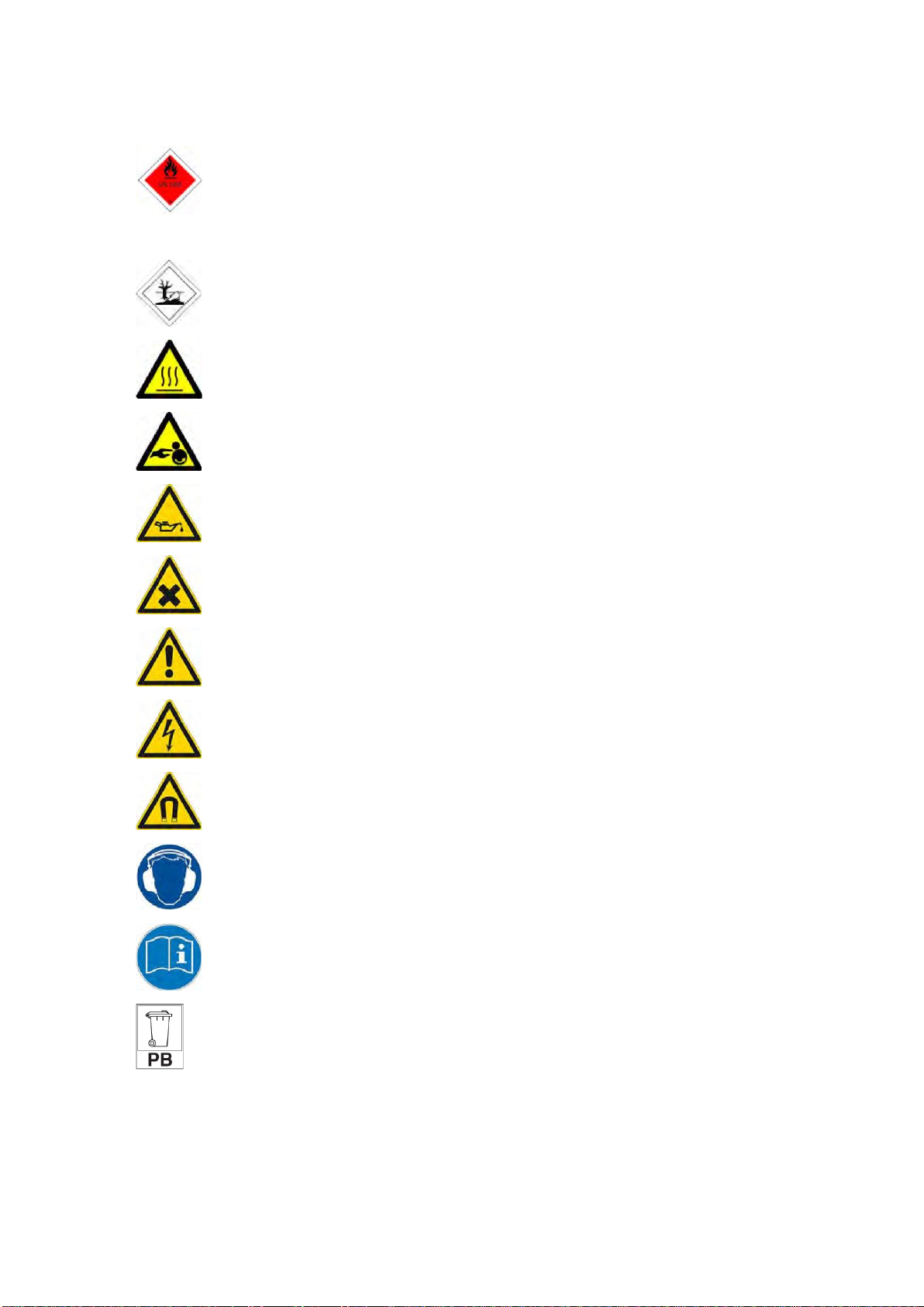
2.1 Warning stickers
Warning stickers are applied to the pump unit as applicable to the specific version. Make sure
these symbols are and remain clearly legible
7
A
Label for the transport of hazardous materials (hazardous goods) in accordance with the
safety standard for the transport of hazardous goods.
TheUN 1202 class 3 placard indicates the presence of gas oil, diesel fuel or light heating
oil.
B
Diesel is hazardous to the environment, with substantial remediation costs if it leaks into
a drain, waterway or the ground.
C
Caution: hot surface
D
Caution: crushing danger
E
Oil
F
Hazardous or irritating substances
G
General hazard
H
Danger: high voltage
I
Danger: magnetic field
J
Wear hearing protection
K
Instructions for use
L
Dispose of in an environmentally responsible manner at the end of the product's useful
life.

8
3
Lifting instructions YAMUNA pump unit
DANGER
Never walk under a raised load. This can result in a life-threatening situation.
WARNING
Always disconnect all external connections before moving the pump unit.
WARNING
Neither the lifting eye on the engine nor the lifting eye of the (bare shaft) pump may
be used for transport of the pump unit.
WARNING
Lifting forces must be as vertical as possible; the maximum lifting angle is 15°.
There is a lifting eye located on the top of the enclosure. Only lift the unit from this lifting eye.
WARNING
If the pump unit is installed on a swampy or muddy surface, the installation may
be ‘stuck’ to the ground.
DANGER
NEVER move or lift the pump unit by the angle profiles on top of the enclosure or
stacking frame.
9
DANGER
The standard lifting eyes on Impulse pump units, both in low-noise enclosure and
open frame, are NOT designed to lift the additional weight of trailers or other
components. It is strictly forbidden to use the standard lifting provision to lift or move
the pump units with a higher total weight than stated in the specification sheets. This
can result
in a life-threatening situation.
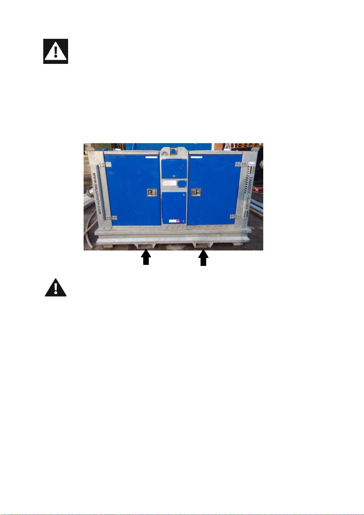
3.1 Moving the pump unit with a forklift
Forklift pockets can be used for moving the pump unit with a forklift. The forks of the forklift
must be inserted into these pockets to lift the pump unit.
WARNING
Use certified lifting equipment with an adequate lifting capacity and always lift from
directly above. Lifting from an angle can lead to dangerous situations.
Lifting work may only be performed by appropriately authorised personnel.
Because many different versions of the pump unit are available, only general
instructions are provided. See the specification sheet for the particular pump unit for
the weight and dimensions.

10
4
Pump unit installation
4.1 Placement –general
WARNING
Failure to follow the guidelines for the placement and installation of the pump can
result in danger to the user and/or severe damage to the pump unit.
Note
Impulse is not responsible for accidents and damage that result from failure to follow the
guidelines in this manual. Such use results in forfeiture of the right to assert any warranty
or damage compensation claims.
−
Place the pump unit on a flat surface capable of supporting the load.
−
Make sure there is sufficient space around the pump unit for operation and maintenanceactivities.
11
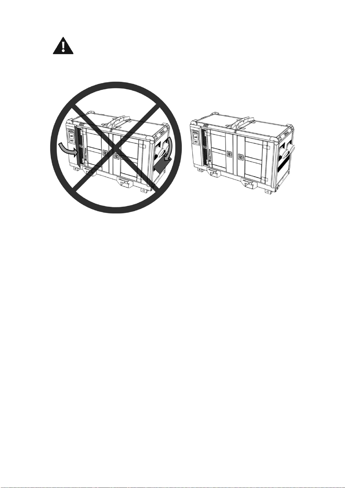
WARNING
Make sure nothing is covering any of the sides of thepump unit, because the sides
of the pump units are used to dissipate heat. The diesel driven pump unit also
usesthe sides for the intake of combustion air and exhaust of combustion gases.
−
When pumping hot liquids, ensure that there is sufficient air circulation to prevent bearings and
lubricants from overheating.
−
Install the prescribed safeguard(s) in the correct manner.
4.2 Outdoor use
The Yamuna pump unit is suitable for outdoor use.
In addition to the general instructions, the following additional requirements must be met:
−
Ensure that there is sufficient free space around the air intake so the engine is able to draw as
much air as it needs.
−
Ensure that there is sufficient free space around the hot air outlet. Maintain at least 2 m (6.6 ft)
of clearance.
−
Avoid dusty conditions and locations where corrosion or erosion can occur..
.
4.3 Indoor use
In addition to the general instructions, the following additional requirements must be met:
−
Ensure that the area has adequate ventilation.
−
Make sure the exhaust gases are discharged outdoors.
−
Ensure that there is sufficient free space around the air intake so the engine is able to draw as
much air as it needs.
−
Prevent high ambient temperature and humidity.
−
Avoid dusty conditions and locations where corrosion or erosion can occur.

12
5
Daily maintenance of the pump
−
Check the oil level of the engine and pump.
Note
If the oil in the pump drive has become whitish in color, replace the oil. The whitish color may
indicate the presence of excessive condensation water in the oil.
−
Check for possible leaks in the oil and fuelhoses.
−
Check the dripping of the gland packing on the
piston rod; this should not exceed one drop every
fiveseconds. It maybenecessary to readjust the
gland packing at greater lift heights.
−
Check that the dripping water can drain away from the gland packing. The channel must notbe
plugged on the outside by dirt and sand that have splashed onto the enclosure.
−
Check whether the machine is still placed properly on theground on which it stands, in accordance
with the instructions. This is important, because the situation canchange as aresult of abuild-up of
sand/soil around the pump unit.
Checking the water trap
The intervals at which you should check the water trap depend entirely on the amount of water in the
fuel and the care taken when refueling.
- Unscrew the bottom of the water trap about 2-3 turns.
- Capture the draining water and fuel in a transparent (glass) vessel. Since water has a greater
specific gravity than diesel fuel, the water emerges before the diesel fuel. The two substances
separate at a clearly visible line.
- As soon as only diesel emerges from the opening, the bottom of the water separator can be
tightened again.

13
14
6
Pump –general
6.1 Preparation for starting the pump unit
The Yamuna series pumps are self-priming piston pumps with rubber piston cups. Before starting
use pump, the pump housing must be filled with water.
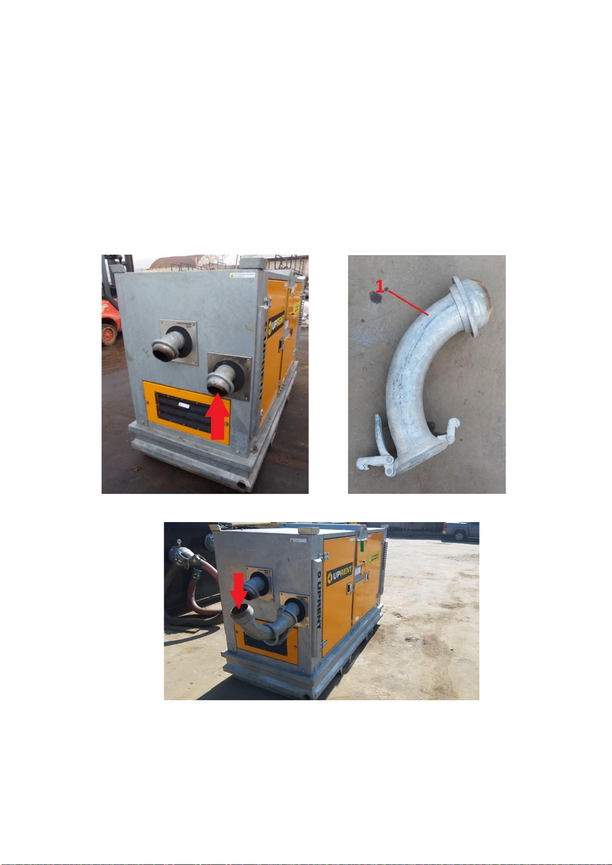
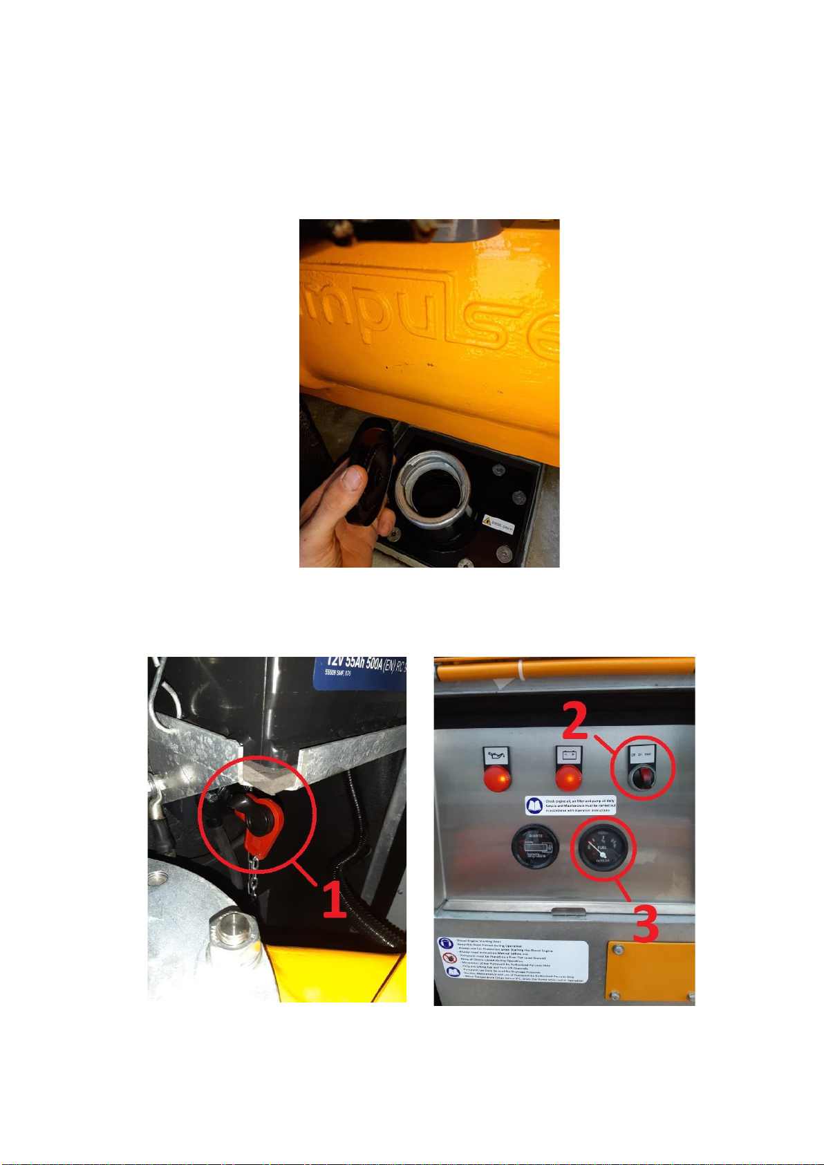
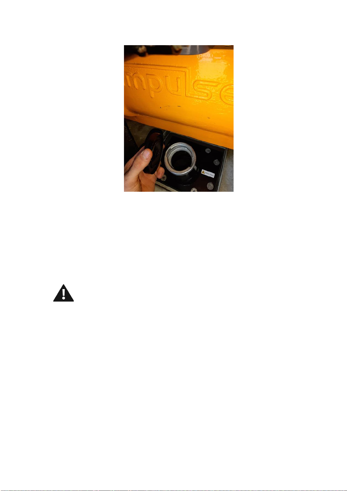
6.2 To fill the pump housing with water:
1.
Fill fully stone catcher with water, through suction side connector it is easier do connecting D100
F/M 90 degree connector (1)
2.
Start the engine, and keep filling the stone catcher with water till its start coming out through
discharge side. When its start coming out pump housing is fully filled with water.
15
6.3 Pump –general
Type 1
Open the fuel tank cup and visually inspect fuel level if necessary fill up.
2 tips
Turn on earth switch 1 and turn egnition switch 2 to posittion “ON”, read reading from fuel level
gauge, if its low fill the fuel.
16
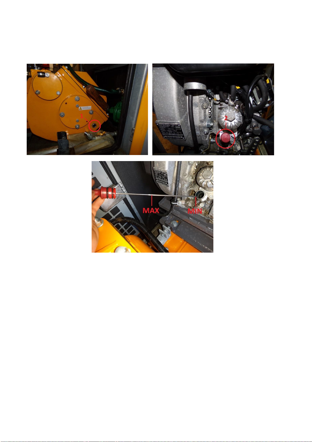
6.4 Preparations for starting
1.
Check the oil level in the drive unit (1) and engine (2).
17
2.
Check fuel level, open the fuel tank cup and visually inspect if fuel is in tank, fill up if necessary
3.
Check fuel lines, for leakage
4.
If applicable, the pump is now warmed up to an adequate temperature (whether it is necessary
to warm up the pump depends on the pumped liquid and the ambient conditions)
5.
Completely open the suction and pressure shut-off valves.
6.
In the case of a bypass line, open the shut-off valve in the bypass line
7.
On a non-enclosed pump set, check whether the protection grilles are in place over the piston
rods
8.
Check whether all the drain plugs and covers are in place.
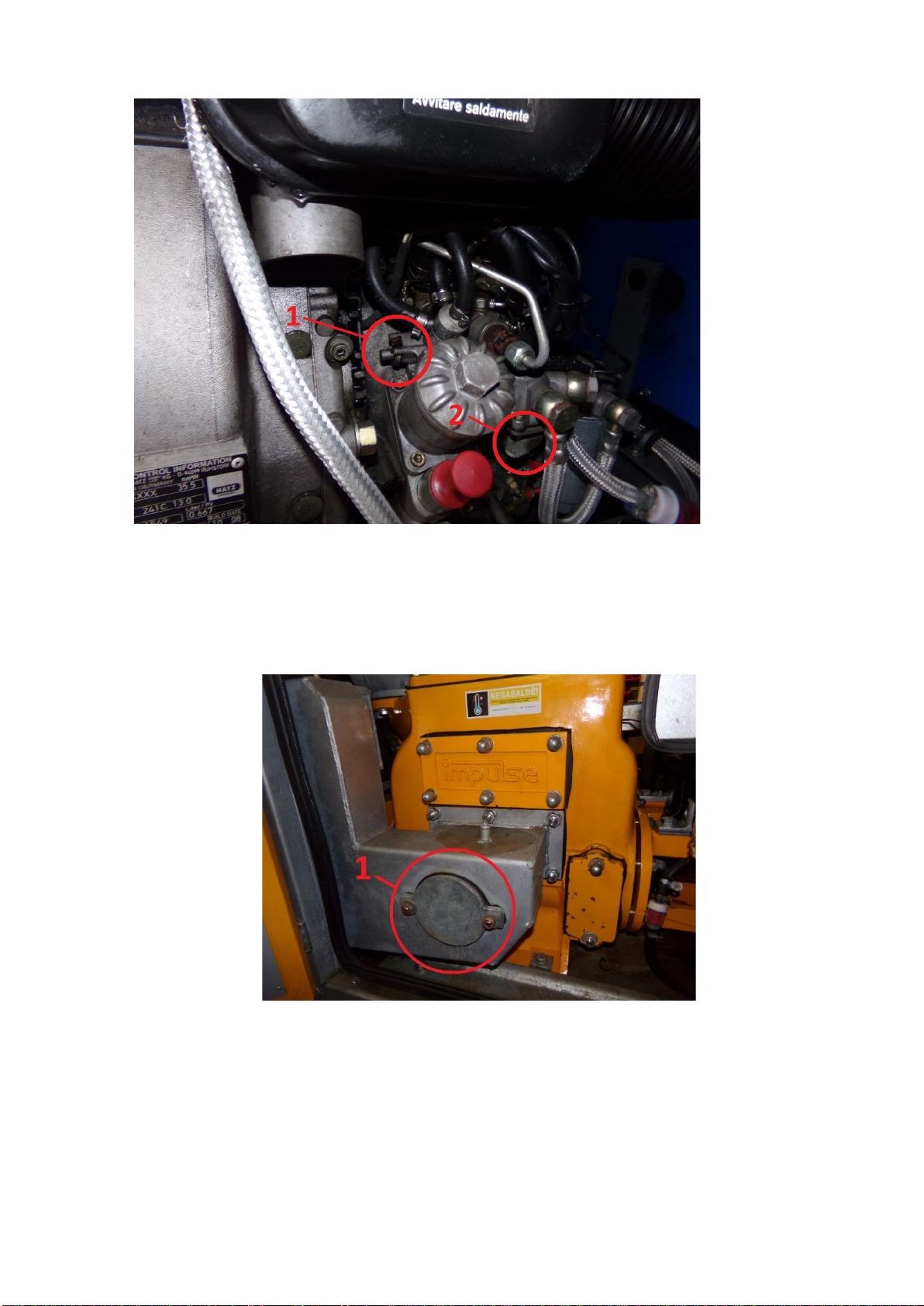
6.5 Priming fuel system
WARNING
Always check fuel level in fuel tank. Don’t start the pump when fuel is running low.
In this case air can get in fuel system.
If air enters the fuel system, the air must be purged from the fuel system before the engine can
be started.
Air can enter the fuel system when the following events occur:
• The fuel tank is empty or the fuel tank has been partially drained.
• The low pressure fuel lines are disconnected.
• A leak exists in the low pressure fuel system.
• The fuel filter is replaced
If air get in the fuel system, its possible to priming system in following steps.
1.
Push lever (1) and hold it.
2.
Pump the lever of feed pump (2) till system is full its can take 1-2 minutes.
18
6.6 Stone catcher cleaning
To clean stone catcher can be done by following steps:
1. Open cover (1), remove all stones and debris.
2. Check conduction of rubber gasket. If it’s in bad conduction replace it.
3. Close cover (1)
4. Open panel (2)

19
5. Open cover (3)
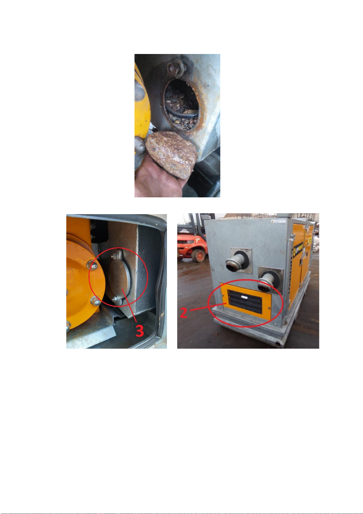
20
6. Remove all debris from stone catcher.
7. Close cover (3) and panel (2).
Table of contents
Popular Water Pump manuals by other brands


GORMAN-RUPP
GORMAN-RUPP SUPER T SERIES Installation, operation and maintenance manual

Lilie
Lilie Shurflo 8000 Series Installation and operation manual

KIRLOSKAR
KIRLOSKAR IN 40/160 IL Instructions on Installation, Operation and Maintenance Manual

K2 Pumps
K2 Pumps Contractor Series owner's manual

MPS
MPS HR1200 user guide

Fluke
Fluke 700HTP-1 instruction sheet

WITA
WITA Wita UPH 15 Installation and operating instructions

emaux
emaux SPV Series user manual

Becker
Becker VASF 1.120/1 operating instructions

Piusi
Piusi Delphin PRO AC Installation, use and maintenance guide

GÜDE
GÜDE RFP 18-0 Translation of the original instructions

samhydraulik
samhydraulik MD10V Installation and commissioning