MPS HR1200 User manual

AN103
User Guide for the HR1200 I2C Kit and GUI
AN103 Rev. 1.0 MonolithicPower.com 1
8/4/2017 MPS Proprietary Information. Patent Protected. Unauthorized Photocopy and Duplication Prohibited.
© 2017 MPS. All Rights Reserved.
User Guide for the
HR1200 I2C Kit and GUI
Application Note
Prepared by Danica Jiang
August 2017

AN103 – USER GUIDE FOR THE HR1200 I2C KIT AND GUI
AN103 Rev. 1.0 MonolithicPower.com 2
8/4/2017 MPS Proprietary Information. Patent Protected. Unauthorized Photocopy and Duplication Prohibited.
© 2017 MPS. All Rights Reserved.
ABSTRACT
This user guide contains guidelines to configure the electrical parameters and program the HR1200.
This guide also provides step-by-step instructions on how to use the GUI and I2C Kit.
AN103 – USER GUIDE FOR THE HR1200 I2C KIT AND GUI
AN103 Rev. 1.0 MonolithicPower.com 3
8/4/2017 MPS Proprietary Information. Patent Protected. Unauthorized Photocopy and Duplication Prohibited.
© 2017 MPS. All Rights Reserved.
QUICK START GUIDE
Preconditions
1) Ensure that the PCB layout of the IC meets our requirements detailed in the AN102 application note,
“HR1200 High Performance PFC+LLC Controller”.
2) Connect the pins of the Kit correctly to the corresponding pins of the IC in the EVB.
Operation Sequence
Start
Connect Kit to USB Port
Press “Scan”
Open GUI
Close GUI
Press “Scan”
Open GUI
Close GUI
Reset Kit and EVB (1)
Reset Kit and EVB (1)
End
Design / Import / Export / ProgramDesign / Import / Export / Program / Monitor / Debug
NOTE:
1) Reset Kit: Ensure that VCC of the Kit is fully discharged below 2V. The discharge time may vary with different application designs.
Reset EVB: Offline mode: Ensure that VCC of the EVB is fully discharged.
Online mode: Ensure that VCC of the EVB is fully discharged and the bus bulk capacitor is discharged below 10V.

AN103 – USER GUIDE FOR THE HR1200 I2C KIT AND GUI
AN103 Rev. 1.0 MonolithicPower.com 4
8/4/2017 MPS Proprietary Information. Patent Protected. Unauthorized Photocopy and Duplication Prohibited.
© 2017 MPS. All Rights Reserved.
TABLE OF CONTENTS
1.Introduction........................................................................................................................................5
2.I2C Function of the HR1200...............................................................................................................5
3.I2C Kit ................................................................................................................................................5
4.USB Isolator ......................................................................................................................................6
5.I2C Interface and Protocols................................................................................................................6
6.Step-by-Step Guide for Offline Programming....................................................................................7
7. Step-by-Step Guide for Online Programming and Monitoring .........................................................15
8.Appendix A: USB Driver Installation ................................................................................................18
9.Appendix B: Register Address.........................................................................................................21
10.Appendix C: Common Faults and Troubleshooting.........................................................................23

AN103 – USER GUIDE FOR THE HR1200 I2C KIT AND GUI
AN103 Rev. 1.0 MonolithicPower.com 5
8/4/2017 MPS Proprietary Information. Patent Protected. Unauthorized Photocopy and Duplication Prohibited.
© 2017 MPS. All Rights Reserved.
1. INTRODUCTION
The HR1200 integrates a digital PFC controller and an analog LLC controller into a single chip. Under
different input and output conditions, the digital PFC enables customers to optimize PFC performance
through programming.
There are 1k bytes of EEPROM available. All design parameters can be written into the chip through
the I2C interface and GUI.
2. I2C FUNCTION OF THE HR1200
The I2C function is workable under two conditions:
1) The IC is in normal operation and no protection has been triggered, particularly under-voltage
lockout (UVLO) and X-cap discharge, which can affect the programming.
2) The IC enters a dedicated test mode when given a pre-determined pulse group on BURST.
Figure 1 shows the HR1200 pins. Pins required for the I2C function are indicated in the red dotted
boxes. For programming, RES and CSP should be connected to GNDD through a 20kresistor. V3.3
should be connected to GNDS through a 4.7 ~ 10µF decoupling ceramic capacitor. GNDS should be
connected with GNDD. For BURST, considering the pull-down resistor in the Kit, the HR1200 BURST
capacitor should be selected carefully to guarantee a full discharge within 100µs.
Figure 1: Pins of the HR1200
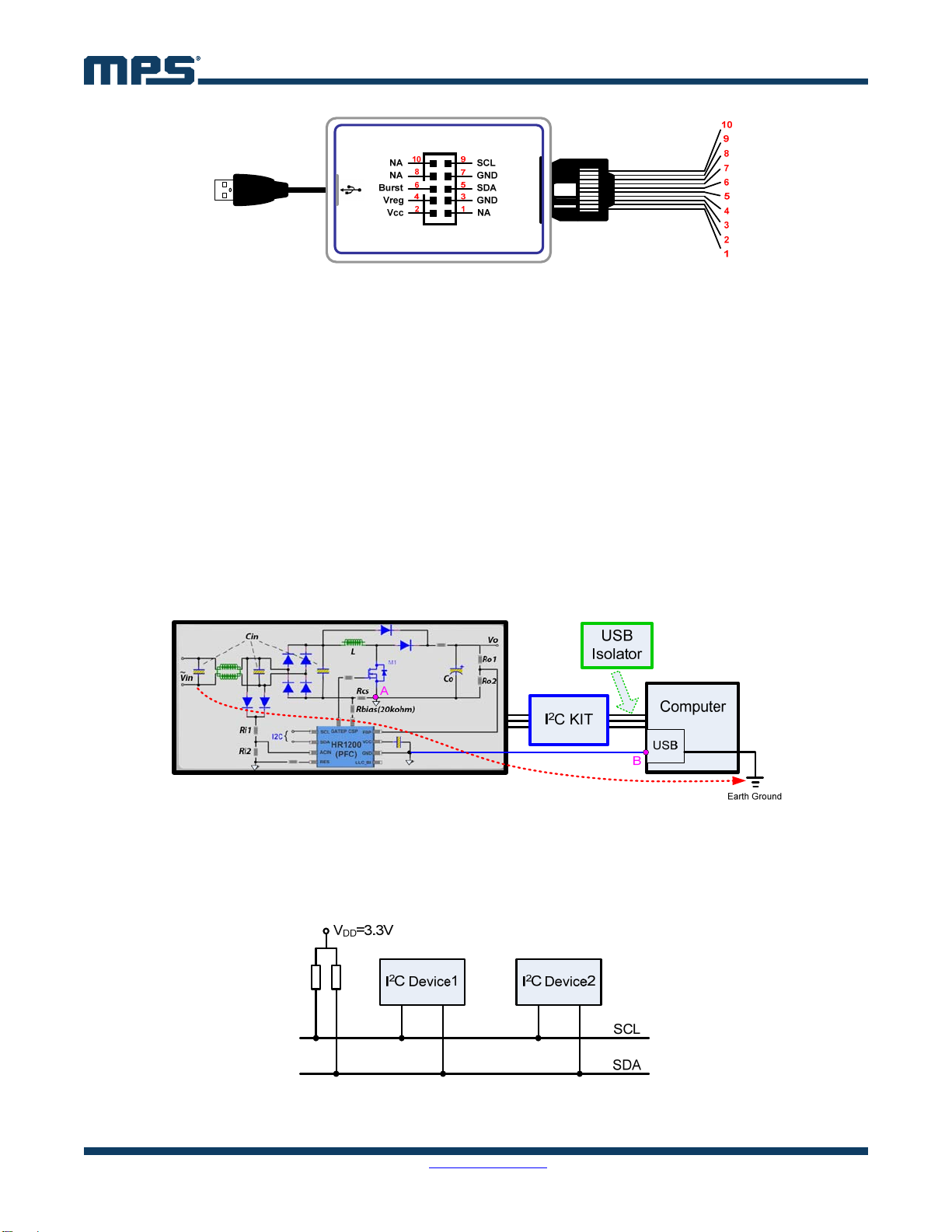
3. I2C KIT
The Kit has six output signals (see Figure 2). GND is the ground reference. SCL and SDA are standard
I2C communication pins. VCC and VREG are power supply pins. BURST is the mode control pin. Kit
pins should be connected to the IC pins in the EVB accordingly.
The computer’s USB port can provide the Kit with 5V DC voltage. Once the Kit connects successfully
with both the USB port and EVB, it can operate in two different modes by detecting the VCC voltage.
Online Mode: If the Kit detects that VCC is higher than 8V when it is hooked up, it will provide
power to VCC only.
Offline Mode: If the Kit detects that VCC is lower than 8V when it is hooked up, it will provide
power to VCC, VREG, and send a pre-determined signal to BURST.
AN103 – USER GUIDE FOR THE HR1200 I2C KIT AND GUI
AN103 Rev. 1.0 MonolithicPower.com 6
8/4/2017 MPS Proprietary Information. Patent Protected. Unauthorized Photocopy and Duplication Prohibited.
© 2017 MPS. All Rights Reserved.
Figure 2: Pins of I2C Kit
When starting up for the first time, it is recommended to program the Kit in offline mode. If the chip is
pre-programmed, this step can be skipped. When programming is finished, remember to close the GUI
and exit the program. To reset the Kit and EVB, disconnect the Kit from the USB port to fully discharge
VCC.
To monitor the input and output of the PFC stage or achieve real-time programming, it is recommended
to run in online mode. For standby power, no load or light load evaluations, it is not recommended to
keep the Kit connected to the board, as the current consumption of the IC will be influenced.
4. USB ISOLATOR
Since the HR1200 is a primary-side controller, its reference ground is coupled to the AC line (point A).
Through the Kit, point A is connected to the USB reference ground of the computer (point B, the
negative side of 5V DC voltage). If the USB reference ground connects with earth ground, there is a
short-circuit path from the line or neutral to earth ground, as shown in Figure 3 with the red dotted line.
Components along the path such as the rectifier bridge and the USB port are at risk of being damaged.
To avoid this, a USB isolator is needed between the I2C Kit and computer USB port.
Figure 3: Short-Circuit Risk
5. I2C INTERFACE AND PROTOCOLS
Aside from the reference ground, the standard I2C/PMBus interface consists of SCL and SDA lines. For
multiple I2C devices, both masters and slaves can be connected to the I2C bus (see Figure 4).
Figure 4: Standard I2C Bus Connection
AN103 – USER GUIDE FOR THE HR1200 I2C KIT AND GUI
AN103 Rev. 1.0 MonolithicPower.com 7
8/4/2017 MPS Proprietary Information. Patent Protected. Unauthorized Photocopy and Duplication Prohibited.
© 2017 MPS. All Rights Reserved.
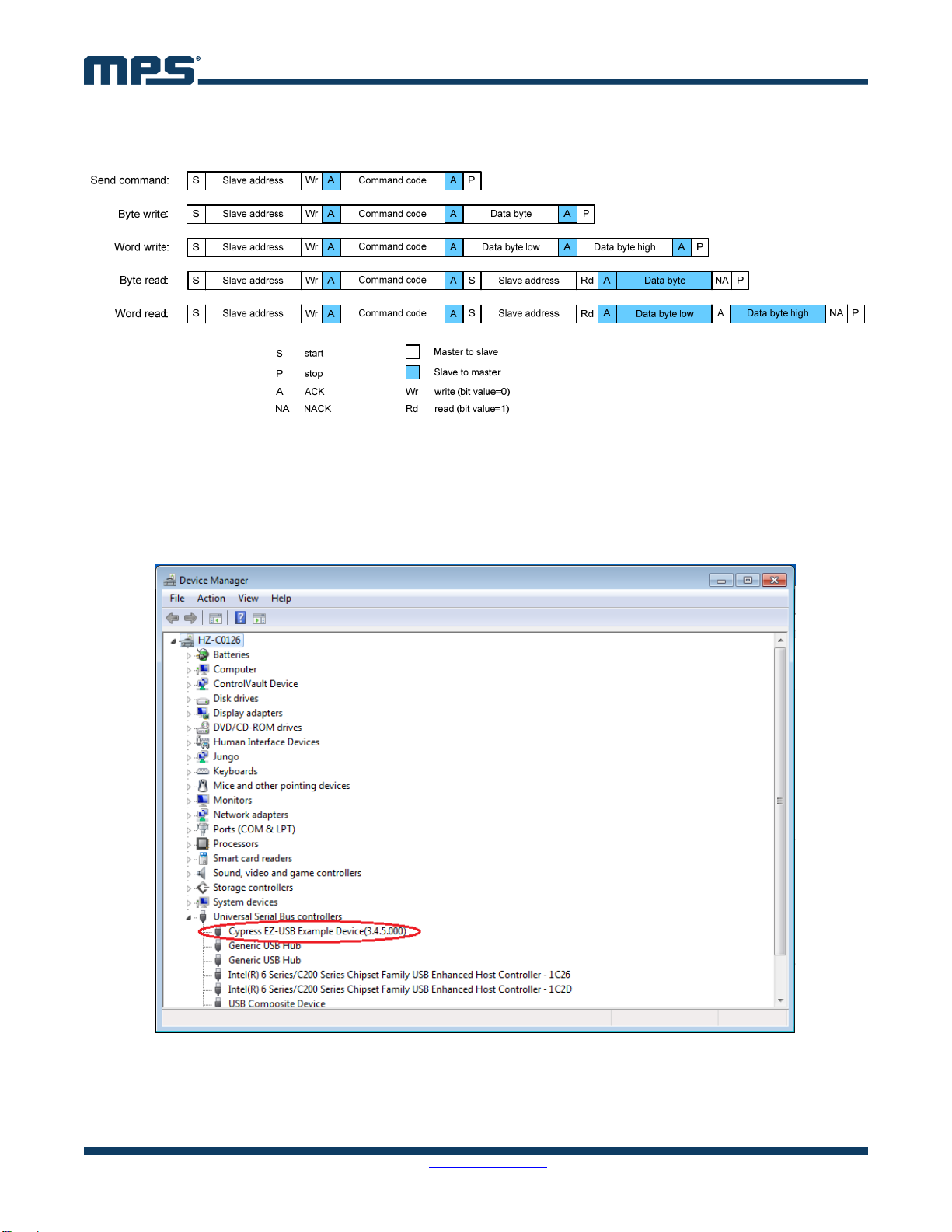
Figure 5 shows various I2C/PMBus protocols supported by the HR1200 under different conditions. The
relevant USB driver should be installed in advance. Refer to Appendix A for installation instructions.
Figure 5: HR1200 I2C Protocols
6. STEP-BY-STEP GUIDE FOR OFFLINE PROGRAMMING
Step 1: Connect the Kit to the computer USB port.
Step 2: Connect the Kit with the EVB after the Kit is recognized by the computer (see Figure 6).
Figure 6: Kit Recognized by Computer
Step 3: Load the GUI folder and double click “HR1200” to start up the GUI (see Figure 7). Then the
interface shown in Figure 8 appears.

AN103 – USER GUIDE FOR THE HR1200 I2C KIT AND GUI
AN103 Rev. 1.0 MonolithicPower.com 8
8/4/2017 MPS Proprietary Information. Patent Protected. Unauthorized Photocopy and Duplication Prohibited.
© 2017 MPS. All Rights Reserved.
Figure 7: GUI Start-Up
Figure 8: GUI Start-Up Interface
Step 4: Press “SCAN”. The Kit performs the following actions automatically.
A. Connection Check
If there is something wrong with the connection between the Kit and USB port, the prompt
box shows: “Please connect I2C Kit to USB port correctly.”
If there is something wrong with the connection between the Kit and EVB, the prompt box
shows: “Please check whether Kit connects to EVB correctly.”
If the Kit connects successfully with both the USB port and EVB, then the Kit proceeds to
Mode Recognition.

AN103 – USER GUIDE FOR THE HR1200 I2C KIT AND GUI
AN103 Rev. 1.0 MonolithicPower.com 9
8/4/2017 MPS Proprietary Information. Patent Protected. Unauthorized Photocopy and Duplication Prohibited.
© 2017 MPS. All Rights Reserved.
B. Mode Recognition: In this case, VCC is below 8V, and the IC enters offline mode (see Figure
9). Fixed VCC, VREG, and pre-determined BURST values are sent to the EVB.
Warning:
DO NOT CONNECT THE AC INPUT in offline mode.
RESET THE KIT AND EVB every time before restarting the GUI. Detach the Kit from USB port and
make sure VCC of both the Kit and EVB is fully discharged before making the connection again.
Figure 9: Main Interface in Offline Mode
Step 5: Configure the parameters of the digital PFC part of the HR1200 by selecting various menu
items on the GUI interface (see the below list). Personal design parameters can also be imported.
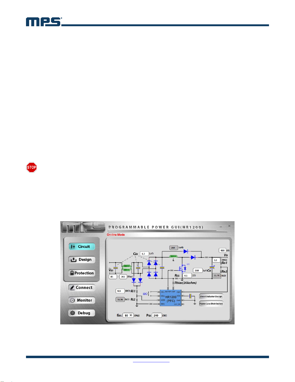
A. Circuit Panel
This panel configures EVB inputs, outputs, and several key design parameters (see Figure 9).
Table 1 explains the circuit panel parameters. Po, Rcs, and Co must be consistent with the actual
circuit. They also affect the bode plots of the power stage in “Loop Design” panel.
Table 1: Circuit Panel Parameters
Item Unit Description Range
Vin_min VAC Minimum input voltage 0 ~ 305
Vin_max VAC Maximum input voltage 0 ~ 305
fin Hz Input voltage frequency 50/60
Cin µF Total input capacitance
Ri1, Ri2 Divider resistor to sense input voltage Ratio is fixed at 0.0032
L µH PFC inductor
Vo V Output voltage 0 ~ 500
Po W Rated output power
Co µF Output capacitance
Ro1, Ro2 Divider resistor to sense output voltage Ratio is fixed at 0.0032
Rcs Current sense resistor
AN103 – USER GUIDE FOR THE HR1200 I2C KIT AND GUI
AN103 Rev. 1.0 MonolithicPower.com 10
8/4/2017 MPS Proprietary Information. Patent Protected. Unauthorized Photocopy and Duplication Prohibited.
© 2017 MPS. All Rights Reserved.
Po and Rcs determine VCOMP_MAX. Since VCOMP_MAX is also limited internally by the chip, the larger Po
is, the smaller Rcs should be. See Equation (1):
256
12
0032.05.06.1)(
2
_
_
refADC
numberbitADC
MAXCOMP V
RcsPodigitalV
(1)
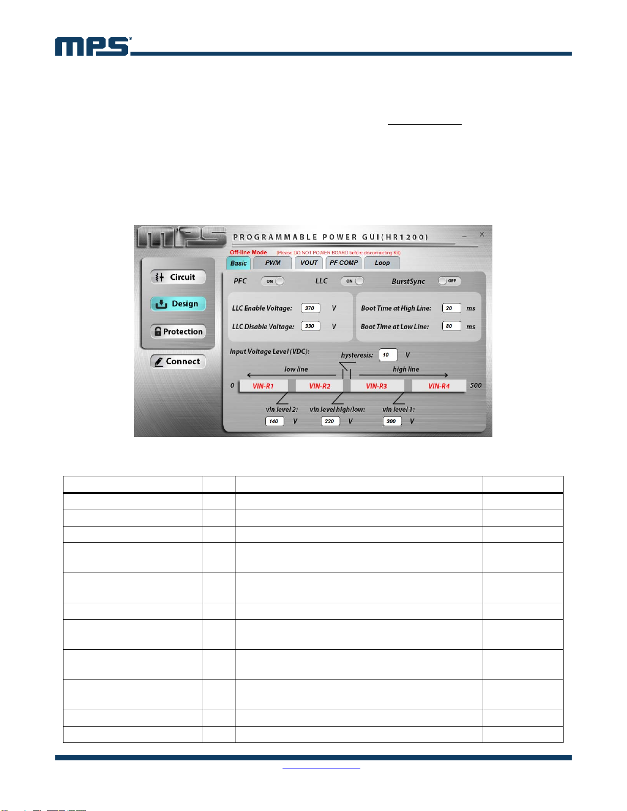
B. Design Panel, Basic
This panel controls the working state of the PFC and LLC separately and configures some basic
parameters (see Figure 10). Table 2 explains the parameters of this panel. The difference between
LLC Enable Voltage and LLC Disable Voltage affects the hold-up time of the converter. The input
voltage is divided into four ranges by vin level 1, vin level high/low, and vin level 2.
Figure 10: Basic Design Panel
Table 2: Basic Design Panel Parameters
Item Unit Description Range
PFC Power on the system ON/OFF
LLC Enable or disable the LLC part ON/OFF
Burst Sync PFC and LLC with same burst frequency ON/OFF
LLC Enable Voltage V Threshold to turn on LLC.
LLC is turned on if the PFC output voltage is larger. 0 ~ 430
LLC Disable Voltage V Threshold to turn off LLC.
LLC is turned off if the PFC output voltage is less.
Less than LLC
Enable Voltage
hysteresis V Input voltage level hysteresis 0 ~ 30
vin level 2 V VIN-R2: vin level 2 + hys < Vin < vin level high/low
VIN-R1: Vin < vin level 2 0 ~ 430
vin level high/low V High line: Vin > vin level high/low + hys
Low line: Vin < vin level high/low 0 ~ 430
vin level 1 V VIN-R4: Vin > vin level 1 + hys
VIN-R3: vin level high/low + hys < Vin < vin level 1 0 ~ 430
Boot Time at High Line ms Soft-start time of the PFC at high-line voltage
Boot Time at Low Line ms Soft-start time of the PFC at low-line voltage

AN103 – USER GUIDE FOR THE HR1200 I2C KIT AND GUI
AN103 Rev. 1.0 MonolithicPower.com 11
8/4/2017 MPS Proprietary Information. Patent Protected. Unauthorized Photocopy and Duplication Prohibited.
© 2017 MPS. All Rights Reserved.
C. Design Panel, PWM
This panel configures parameters related to the PWM switching of the PFC (see Figure 11).
Specific parameter descriptions are shown in Table 3.
Figure 11: PWM Design Panel
Table 3: PWM Design Panel Parameters
Item Unit Description Range
Maximum Frequency kHz Set different maximum switching frequencies
according to different input ranges 40 ~ 160
Minimum Frequency kHz Set different minimum switching frequencies
according to different input ranges 20 ~ 160
Min. Turn-On Time µs Minimum turn-on time of the PFC MOSFET 0 ~ 1.5
Min. Turn-Off Time µs Minimum turn-off time of the PFC MOSFET 0 ~ 1.5
Frequency Jitter Enable or disable frequency jitter function ON/OFF
Frequency Jitter Amp (2) kHz Amplitude of frequency jitter 0 ~ 100
Jitter Modulation Freq (2) Hz Modulation frequency of frequency jitter 100 ~ 4000
Valley Turn-On (ZCD) Valley turn-on or turn-off in DCM ON/OFF
ZCD Period (high line) (3) µs
Average resonant period of MOSFET VDS at
high line in DCM 0 ~ 6
ZCD Period (low line) (3) µs
Average resonant period of MOSFET VDS at
low line in DCM 0 ~ 6
NOTES:
2) Frequency Jitter Amp and Jitter Modulation Freq can only be changed online when Frequency Jitter is enabled.
3) To achieve zero-voltage switching (ZVS) in discontinuous conduction mode (DCM), ZCD Period must be measured manually before it
can be filled in.
AN103 – USER GUIDE FOR THE HR1200 I2C KIT AND GUI
AN103 Rev. 1.0 MonolithicPower.com 12
8/4/2017 MPS Proprietary Information. Patent Protected. Unauthorized Photocopy and Duplication Prohibited.
© 2017 MPS. All Rights Reserved.
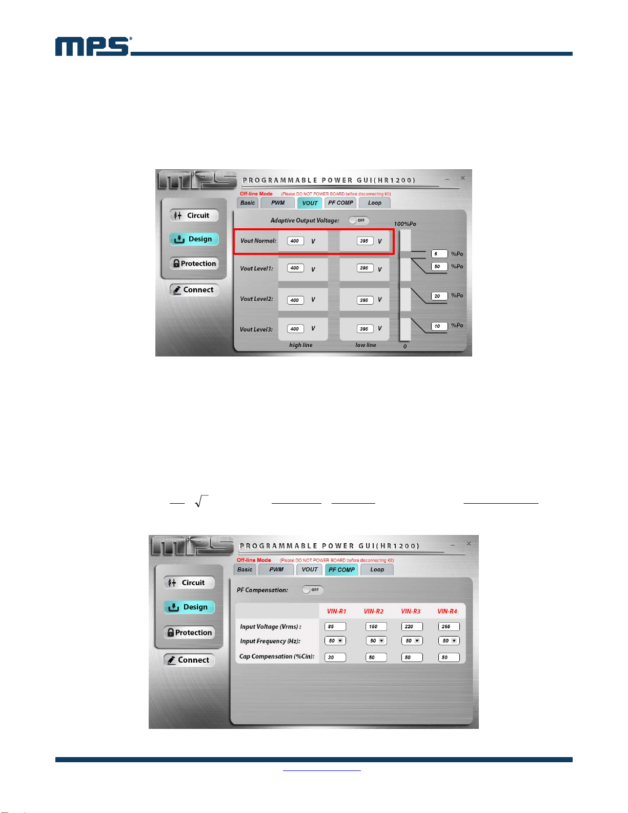
D. Design Panel, VOUT
This panel can configure the PFC output voltage according to different input ranges and output
power to optimize efficiency.
When Adaptive Output Voltage is enabled, there are eight adjustable PFC output voltages. When
Adaptive Output Voltage is disabled, the PFC output voltage only can be set according to the high-
line or low-line input (see red box in Figure 12).
Figure 12: VOUT Design Panel
E. Design Panel, PF COMP
This panel configures the PF compensation parameters, which can improve the power factor (PF)
of the PFC stage. Compensation can be controlled in different degrees according to different input
ranges (see Figure 13). Five factors influence the compensation degree: Cin and Rcs in “Circuit”
panel, Input Voltage, Input Frequency, and Cap Compensation.
For example, the compensation amplitude of input current reference in VIN-R1 can be calculated
with Equation (2):
refADC
numberbitADC
REF_COMP V
RcsfinPF
CinCapPF
VinPF
π
I
_
3
1
12
1_
1000000100
1_
1_2
4
(2)
Figure 13: PF COMP Design Panel

AN103 – USER GUIDE FOR THE HR1200 I2C KIT AND GUI
AN103 Rev. 1.0 MonolithicPower.com 13
8/4/2017 MPS Proprietary Information. Patent Protected. Unauthorized Photocopy and Duplication Prohibited.
© 2017 MPS. All Rights Reserved.
F. Design Panel, Loop
This panel can determine the load point to enter burst mode by configuring Burst Mode Load.
Additionally, Kp and Ki of the closed-loop control can be set. Figure 14 shows the voltage closed-
loop control block diagram.
ooCSV
sCVRR
1
5.0
1
V
R
s
KsK
ip
refo
V
_
o
V
error
comp
V
Figure 14: Voltage Closed-Loop Control
If Setup Mode is set as “Auto”, Kp and Ki are kept as defaults.
If Setup Mode is set as “Manual”, Kp and Ki can be changed. The related bode plots are shown to
help check gain and phase margin of the loop (see Figure 15).
During load dynamics, if the PFC output voltage decreases from Vset to Vset minus FastLoop
Voltage, the internal Ki and Kp increase FastLoop Gain times. In this way, the PFC has a very fast
loop gain, allowing it to reach the target value faster.
Figure 15: Loop Design Panel
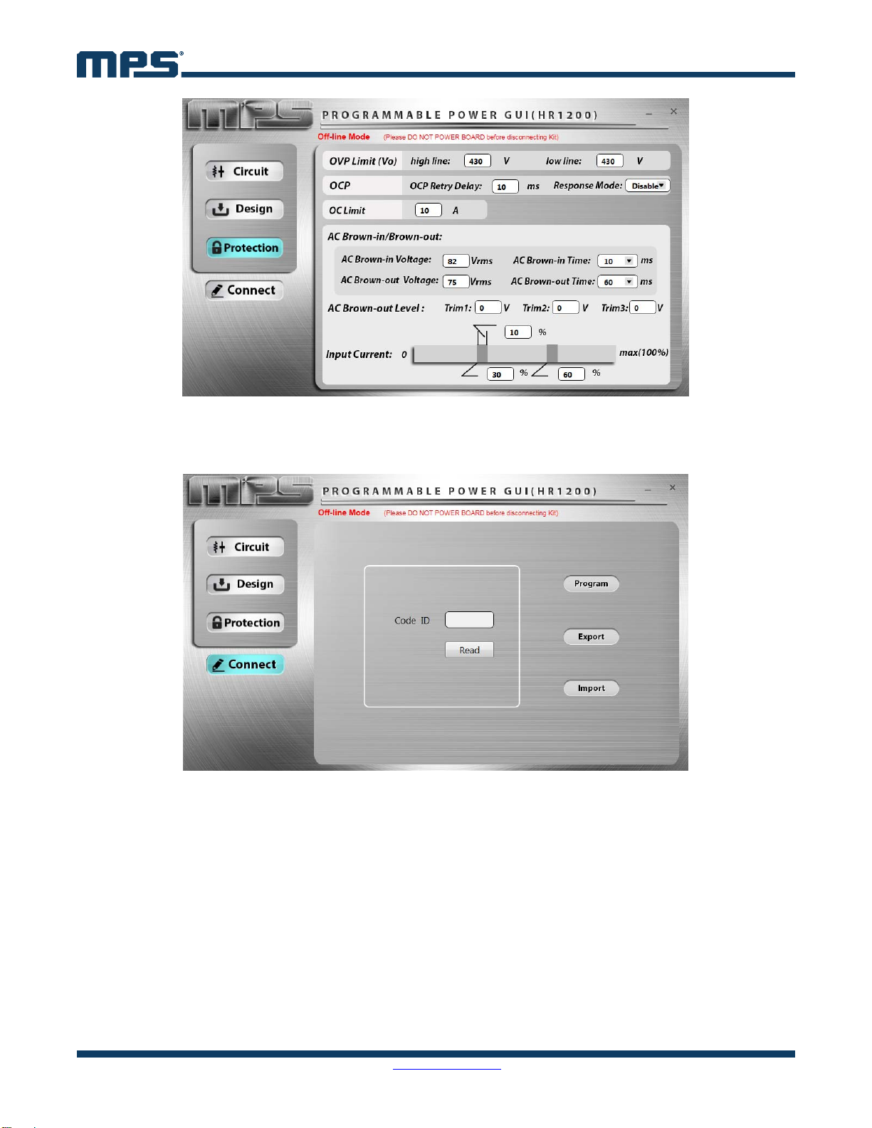
G. Protection Panel
This panel configures the AC brown-in/brown-out voltage and several protection parameters
including OVP, OCP, OC limit, etc (see Figure 16).
To precisely compensate the AC brown-out voltage, Trim1, Trim2 and Trim3 are introduced.
Please refer to Appendix B for the corresponding register address.
AN103 – USER GUIDE FOR THE HR1200 I2C KIT AND GUI
AN103 Rev. 1.0 MonolithicPower.com 14
8/4/2017 MPS Proprietary Information. Patent Protected. Unauthorized Photocopy and Duplication Prohibited.
© 2017 MPS. All Rights Reserved.
Figure 16: Protection Panel
Step 6: Go to “Connect” panel to program the IC after all of the parameters have been configured (see
Figure 17).
Figure 17: Connect Panel
Press “Program” to program all panel parameters to the EEPROM of the HR1200. When programming
is finished, the EEPROM data are read out and compared with the original written values to perform a
self-check. If something is wrong, a corresponding prompt box displays. If there are no errors, following
prompt box is displayed: “Program successfully.”
Press “Export” to save all the panel parameters in a Microsoft Excel spreadsheet.
Press “Import” to load data from a external Excel spreadsheet into the GUI panels. Ensure that the
external Excel spreadsheet has the same form as the one exported from the GUI.
Step 7: Close the GUI. As the panel parameters restore default values every time restarting the GUI, it
is better to save the current panel parameters before exiting.
Step 8: Reset Kit and EVB (1).
AN103 – USER GUIDE FOR THE HR1200 I2C KIT AND GUI
AN103 Rev. 1.0 MonolithicPower.com 15
8/4/2017 MPS Proprietary Information. Patent Protected. Unauthorized Photocopy and Duplication Prohibited.
© 2017 MPS. All Rights Reserved.
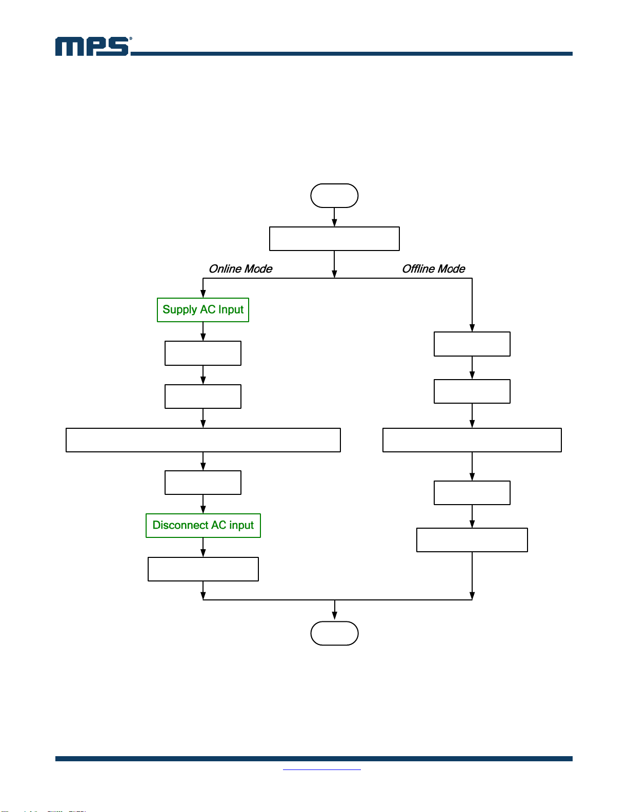
7. STEP-BY-STEP GUIDE FOR ONLINE PROGRAMMING AND MONITORING
To operate the HR1200 GUI in online mode, follow the steps below.
Step 1: Connect the Kit to the computer USB port.
Step 2: Connect the Kit to the EVB after the Kit is recognized (see Figure 6).
Step 3: Supply AC input to power up the EVB.
Step 4: Load the GUI folder and open the GUI (see Figure 7 and Figure 8).
Step 5: Press “SCAN”. The Kit performs the following actions automatically.
A. Connection Check
If there is something wrong with the connection between the Kit and USB port, the prompt
box displays: “Please connect I2C Kit to USB port correctly.”
If there is something wrong with the connection between the Kit and EVB, the prompt box
displays: “Please check whether Kit connects to EVB correctly.”
If the Kit connects successfully with both the USB port and EVB, the Kit proceeds to Mode
Recognition.
B. Mode Recognition: In this case, VCC is above 8V, and the IC enters online mode (see Figure
18). Only the fixed VCC value is sent to the EVB.
Warning:
USE A USB ISOLATOR between the Kit and USB port as suggested in Section 4.
KEEP THE AC INPUT IN CONNECTION in online mode.
DO NOT PLUG OR UNPLUG ANY DEVICE in online mode to prevent damaging the EVB.
RESET THE KIT and EVB every time before restarting the GUI. Detach Kit from the USB port and
make sure VCC of both the Kit and EVB is fully discharged. In online mode, the bus bulk capacitor
should be discharged below 10V to prevent false triggering before making connection again.
Figure 18: Main Interface in Online Mode
Step 6: Configure the parameters of the digital PFC part of the HR1200 through the GUI. In addition to
the panels introduced in Section 6, there is a special panel in online mode.

AN103 – USER GUIDE FOR THE HR1200 I2C KIT AND GUI
AN103 Rev. 1.0 MonolithicPower.com 16
8/4/2017 MPS Proprietary Information. Patent Protected. Unauthorized Photocopy and Duplication Prohibited.
© 2017 MPS. All Rights Reserved.
H. Monitor Panel
This panel provides the function of monitoring the status of the HR1200. The input/output of the
PFC stage can be checked to determine the fault state (see Figure 19).
Figure 19: Monitor Panel
Step 7: If the parameters in “Circuit”, “Design”, or “Protection” panels have been changed and need to
be programmed to the chip, use “Connect” panel, which is still effective in online mode.
Online mode also has a special “Debug” button. This controls the turning-on and turning-off of the real-
time programming function (see Figure 20).
Real-Time Programming
When pressed, the “Debug” button becomes orange. Then the real-time programming function
is turned on. Any single change in any panel can be programmed to the chip in real time by
pressing ENTER immediately. Under this condition, the “Import” function is disabled.
Press “Debug” again to turn off real-time programming function. Then the button restores gray.
Figure 20: Debug Button

AN103 – USER GUIDE FOR THE HR1200 I2C KIT AND GUI
AN103 Rev. 1.0 MonolithicPower.com 17
8/4/2017 MPS Proprietary Information. Patent Protected. Unauthorized Photocopy and Duplication Prohibited.
© 2017 MPS. All Rights Reserved.
Warning:
REAL-TIME PROGRAMMING IS A RISKY PROGRAMMING MODE. If you make a change in a data
box and press ENTER, then all panel parameters, not only the one changed, will be programmed to
the chip. PLEASE CONFIRM PANEL PARAMETERS before pressing ENTER.
DO NOT FORGET TO PRESS ENTER during real-time programming. Otherwise, the data change in
GUI will not be updated to the chip
Step 7: Close the GUI. Since the panel parameters restore the default values whenever the GUI
restarts, it is better to save current panel parameters before exiting.
Step 8: Disconnect the AC input.
Step 9: Reset the Kit and EVB (1).
AN103 – USER GUIDE FOR THE HR1200 I2C KIT AND GUI
AN103 Rev. 1.0 MonolithicPower.com 18
8/4/2017 MPS Proprietary Information. Patent Protected. Unauthorized Photocopy and Duplication Prohibited.
© 2017 MPS. All Rights Reserved.
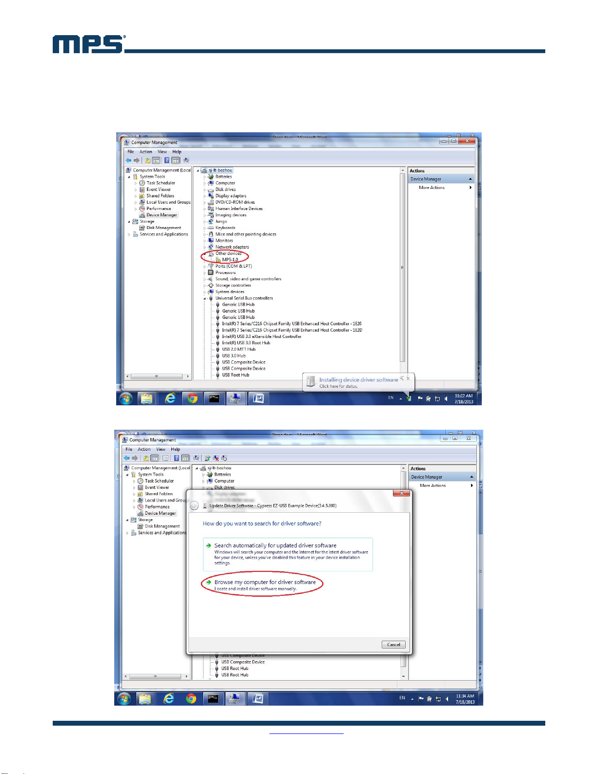
8. APPENDIX A: USB DRIVER INSTALLATION
Step 1: Disconnect the SDL, SDA, and GND cable.
Step 2: Connect the USB board to the computer via USB cable. There should be an unrecognized
device in the device manager.
Step 3: Update the drivers.
AN103 – USER GUIDE FOR THE HR1200 I2C KIT AND GUI
AN103 Rev. 1.0 MonolithicPower.com 19
8/4/2017 MPS Proprietary Information. Patent Protected. Unauthorized Photocopy and Duplication Prohibited.
© 2017 MPS. All Rights Reserved.
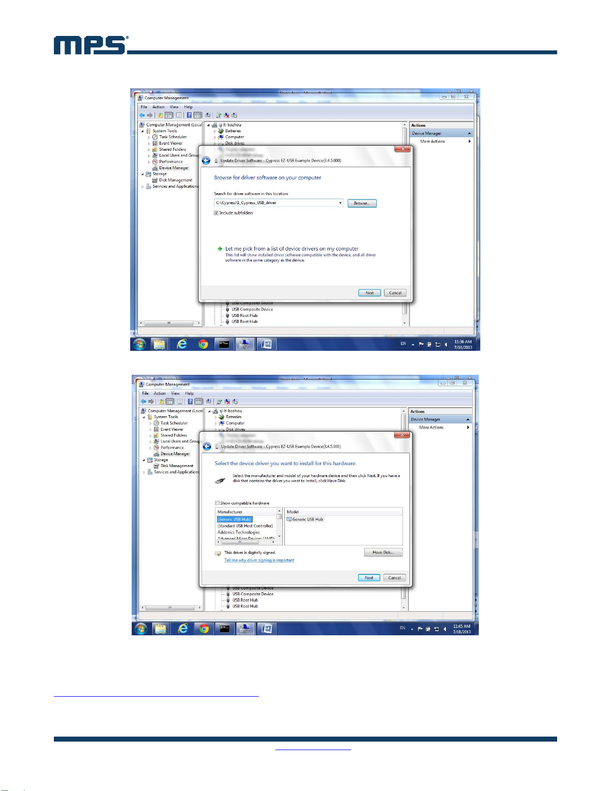
Step 4: Click on “Browse my computer for driver software”.
Step 5: Navigate to X:\1_Cypress_USB_driver\
This folder includes all the digitally signed CyUSB driver .inf, .cat, and .sys files. Only the digitally
signed USB driver could work with a 64-bit operation system.
You may also find this resource from Cypress Website signed CyUSB.sys driver:
http://www.cypress.com/?id=4&rID=53338
For WINXP and WIN7 32-bit OS, the system searches for the driver file automatically. Follow the
instructions and click “Next”.
AN103 – USER GUIDE FOR THE HR1200 I2C KIT AND GUI
AN103 Rev. 1.0 MonolithicPower.com 20
8/4/2017 MPS Proprietary Information. Patent Protected. Unauthorized Photocopy and Duplication Prohibited.
© 2017 MPS. All Rights Reserved.
WINXP: the driver is under X:\1_Cypress_USB_driver\cyusbfx1_fx2lp\wxp\
WIN7 32-bit: the driver is under X:\1_Cypress_USB_driver\cyusbfx1_fx2lp\wlh-win7\x86
For WIN7 64-bit OS, the USB driver can only be installed manually. Select “Let me pick from a list of
device drivers on my computer”.
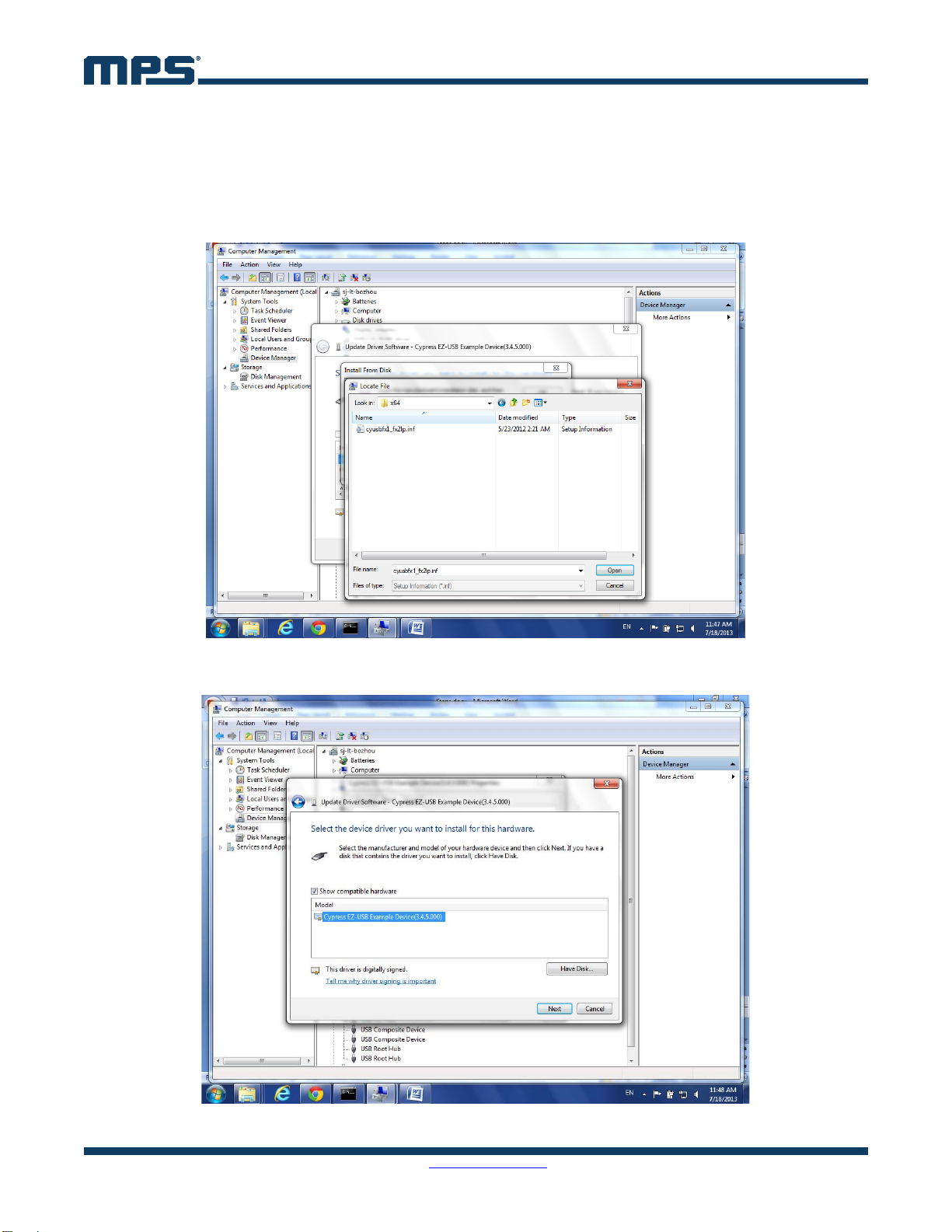
Step 6: Click on “Have Disk” and select “Browse”.
Step 7: Navigate to X:\ MPS\MPSDemo\Drivers\cyusbfx1_fx2lp\wlh-win7\x64\cyusbfx1_fx2lp.inf. Click
on “Open” and select “OK”.
Step 8: Choose “Cypress EZ-USB Example Device” and select “Next”. The USB driver will be installed.
Table of contents
Other MPS Water Pump manuals


Popular Water Pump manuals by other brands


Clarke
Clarke Strong Arm CS10PRH Operating & maintenance instructions

Accudyne Industries
Accudyne Industries Milton Roy Milroyal Series instruction manual

Bijur Delimon
Bijur Delimon BS-B operating instructions

Clarke
Clarke IVP14A Operation & maintenance instructions

Flotec
Flotec EVO-MULTIMAX 340 LOGIC SAFE instruction manual

Sealey
Sealey TP6801 instructions