IMV SmartVibro VM-3024S User manual

-1-
VM-3024S/H Instruction Manual
(Compatible with Version 2.16 or later)
Instruction Manual
Portable Vibrometer
SmartVibro Series
Model: VM-3024S
VM-3024H
Manufacture: IMV CORPORATION
Document No.: TVE-6-3790E
Revision Date: 18th June, 2021
Page: 44
Revision: 3.0.0
-2-
VM-3024S/H Instruction Manual
(Compatible with Version 2.16 or later)
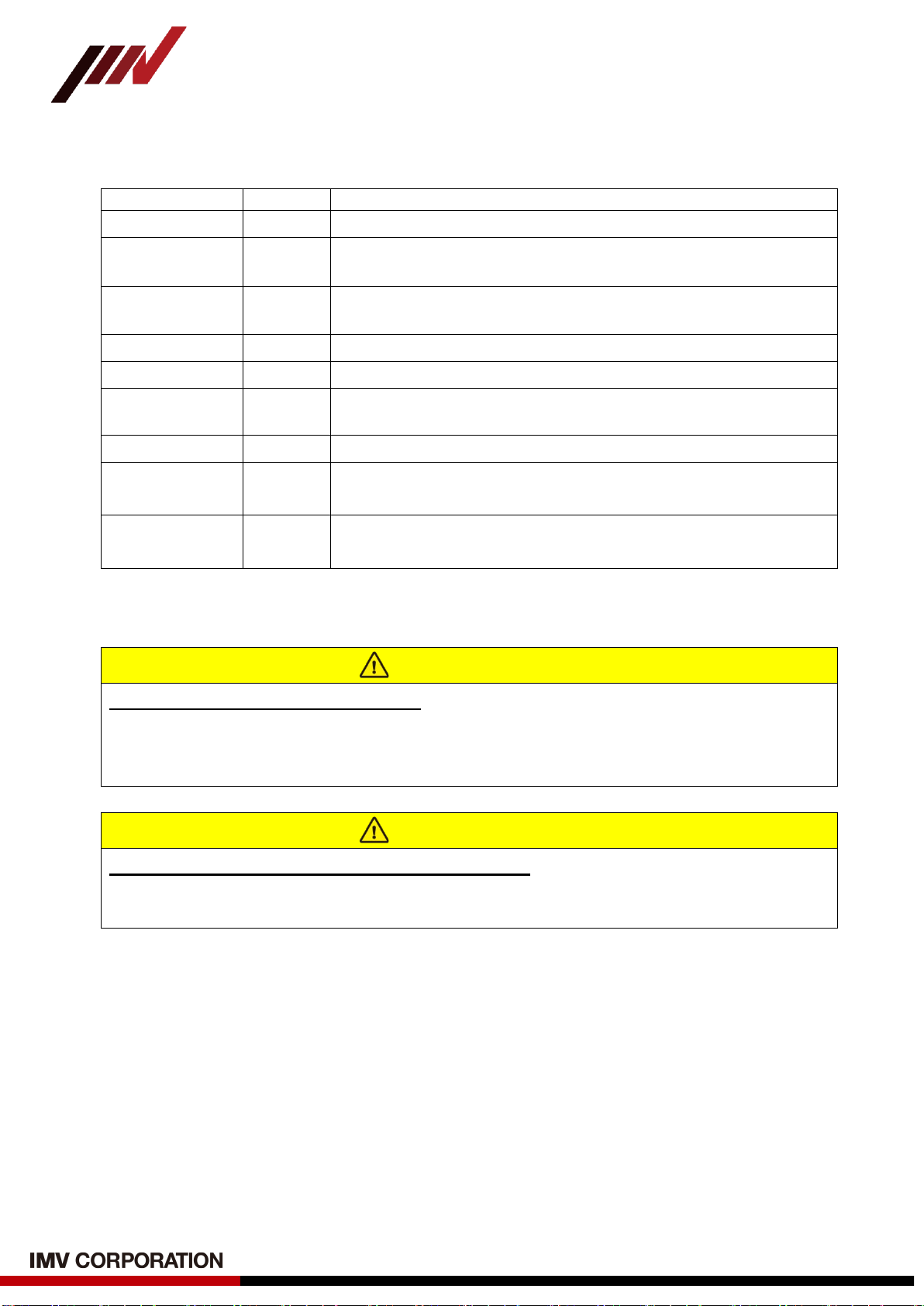
Revision History
Date
Rev.
Details
3rd Feb, 2012
1.0.0
New Issue.
22th Mar, 2012 1.0.1 (1) Corrected Figures and phrases.
(2) Added optional accessories.
6th Apr, 2012 1.0.2
(1) Added Preparation (3-1).
(2) Added “How to Fix the Pickup” (10).
3rd Oct, 2012
1.0.3
Corrected AC OUT Sensitivity (4-4)
21th Dec, 2012
1.5.0
Added “Password Function” (4-11).
20th Feb, 2013 1.5.1
Corrected Cable Model.
CE-3004
→
CE-3024
28th Jan, 2016
1.5.3
Corrected AC Adapter Model Number.
10th May, 2016 2.0.0 (1) Ver2.00 and overall review.
(2) SmartVibro screen and wording were corrected.
18th June, 2021 3.0.0 (1) Ve r2.16 or later compatible and overall review.
(2) Removed “Chinese” from language (end of support).
Important Notice
EOL of Standard Model (VM-3024S)
The standard model (VM-3024S) was discontinued as of 30th
September, 2014.
Thank you in advance for your understanding.
Please contact us for product maintenance.
Important Notice
End of support about language display "Chinese"
The support of language display "Chinese" has ended 17th June, 2021.
Thank you in advance for your understanding.

-3-
VM-3024S/H Instruction Manual
(Compatible with Version 2.16 or later)
INDEX
1. Introduction ............................................................................................................................. 4
1-1. Panel Description.............................................................................................................. 5
1-2. Package Contents .............................................................................................................. 6
2. Outline..................................................................................................................................... 7
2-1. SmartVibro Overview ....................................................................................................... 7
2-2. Features............................................................................................................................. 7
3. Measurement ........................................................................................................................... 8
3-1. Before Getting Started ...................................................................................................... 9
3-2. Measurement Screen ....................................................................................................... 10
3-3. Operations during Measurement ......................................................................................11
4. Setting.................................................................................................................................... 13
4-1. Mode Setting................................................................................................................... 15
4-2. Calculation Setting.......................................................................................................... 16
4-3. Setting of Auto Range..................................................................................................... 18
4-4. Sensitivity Setting of AC and DC Output ....................................................................... 19
4-5. Setting of Battery Type, Auto Power Off, and Contrast.................................................. 21
4-5-1. Setting of Battery Type ............................................................................................ 22
4-5-2. Setting of Auto Power Off Function......................................................................... 22
4-5-3. Setting of Contrast ................................................................................................... 22
4-6. Language Setting ............................................................................................................ 23
4-6-1. Language Setting...................................................................................................... 23
4-6-2. Version Information ................................................................................................. 24
4-7. Password Function .......................................................................................................... 25
4-7-1. Password Setting ...................................................................................................... 25
4-7-2. Password Input......................................................................................................... 27
4-8. Battery Indicator ............................................................................................................. 28
5. FFT and Data Save ................................................................................................................ 29
5-1. FFT ................................................................................................................................. 30
5-1-1. FFT Indication.......................................................................................................... 30
5-1-2. FFT Setting .............................................................................................................. 32
5-2. Data Save ........................................................................................................................ 32
5-2-1. Waveform Data Save................................................................................................ 32
5-2-2. Setting of Waveform Data Save ............................................................................... 35
6. Conversion Table ................................................................................................................... 37
7. Specifications ........................................................................................................................ 38
7-1. SmartVibro...................................................................................................................... 38
7-2. Pickup ............................................................................................................................. 38
7-3. Outer Dimensions of SmartVibro.................................................................................... 39
7-4. Outer Dimensions of Pickup and Probe .......................................................................... 40
8. Troubleshooting..................................................................................................................... 41
9. Precautions ............................................................................................................................ 41
10. How to Fix the Pickup and Frequency Characteristics ........................................................ 42
11. Definitions ........................................................................................................................... 44

-4-
VM-3024S/H Instruction Manual
(Compatible with Version 2.16 or later)
1. Introduction
Thank you for purchasing Portable Vibrometer “VM-3024S/H”.
Please read this manual carefully before use and follow the cautions below for your safety.
Safety Precautions
This chapter describes several items which we would like to you observe in order to use
the product safety and prevent injury to customers and other persons and damage to
property. Please be sure to read this instruction manuals and attached documents before
use, and fully understand the contents for use.
After reading this manual, be sure to place it in a location so that you can always refer to it.
●Expressions of safety instructions
Calls attention to a procedure, practice, or condition that could possibly
cause death or bodily injury.
Calls attention to a procedure, practice, or condition that could possibly
cause bodily injury or damage to instrument.
Represent handling precautions or notes on product specifications.
Indicates product specification information and actual usage information.
●For safe use
In case of the place of objective instrument is high temperature, near rotating
shaft and near a moving element, the mounting of pick-up, please go to when
the machine is stopped.
In such a place, measuring the vibration with pick-up in one’s hand, it causes
burn injury and cable engulfment. It is very dangerous, please stop
absolutely.
Stop using the instrument, when producing smoke, bad smell or noise. It
causes fire or shock hazard.
Turn off the power switch and unplug the power cable from outlet as soon
as possible, please contact the agency or IMV. To reduce risk of injury, take
it to a qualified serviceman when service or repair is required.
Do not substitute parts or modify instrument.
It causes bodily injury, fire or shock hazard.
Stop using the instrument, when an object or liquid falls/spills into the
instrument. It causes fire or shock hazard.
Turn off the power switch and unplug the power cable from outlet as soon
as possible, please contact the agency or IMV.
Do not expose the instrument to moisture or dust.
If causes fire or shock hazard.
When replacing or disposing of the battery, follow the precautions on the
battery.
Also, pay attention to the polarity when replacing.
When the product is not used for a long time, turn off the power switch and
store it with the battery removed.
Storing the battery with the battery inside may cause a malfunction due to
liquid leakage.
Danger
Warning
Caution
Danger
Warning
Warning
Warning
Caution
Caution
Caution

-5-
VM-3024S/H Instruction Manual
(Compatible with Version 2.16 or later)
1-1. Panel Description
VM-3024 is available in Standard Model (VM-3024S) or High-End Model (VM-3024H).
Icons appeared on the display are different in each model. Each screen display example
is shown below.
High-end model has these two icons when the machine is turned on.
VM-3024 can be switched freely between Japanese and English.
●Standard Model (VM-3024S)
(Japanese) (English)
●High-End Model (VM-3024H)
(Japanese) (English)
The basic measurement operations will be explained on the screen of the high-end model
(VM-3024H) (Section 3). Operation method is the same for the standard model (VM-3024S)
as well. Additional functions of the high-end model, VM-3024H, will follow in section 5.
-6-
VM-3024S/H Instruction Manual
(Compatible with Version 2.16 or later)
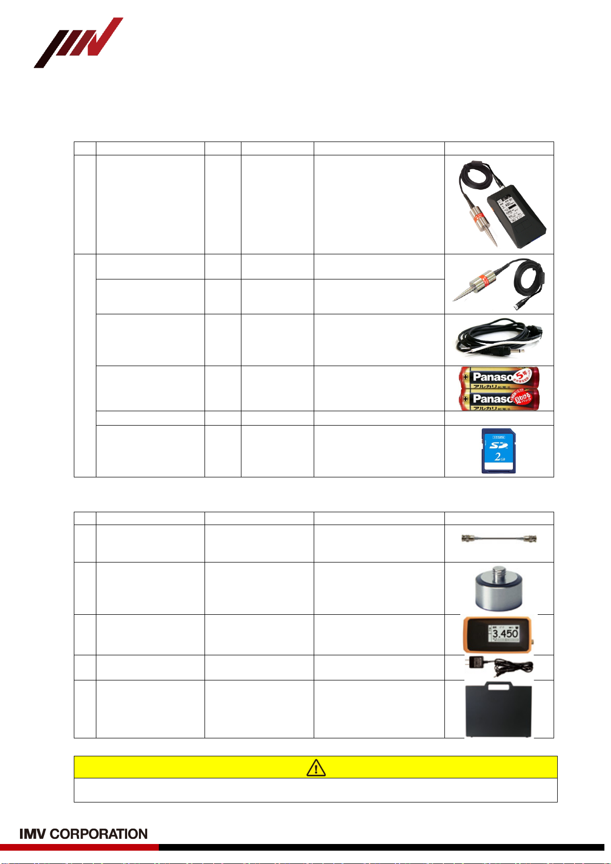
1-2. Package Contents
Product and Accessories for the VM-3024.
(1) Basic Product and Accessories
Products
Qty
Model
Note
Figure
Main Unit
SmartVibro 1
VM-3024S
or
VM-3024H
Accessories
Pickup 1 VP-3024
Electrodynamic Velocity
Type
Probe 1 -Handheld probe
φ10×50mm
Output Cable 1 -
1.5m cable with a plug at
one end.
For output to a recorder
etc.
Battery 1 -AA Alkaline
Batteries
Instruction Manuals
1
-
with Inspection Sheet
SD Card 1 -VM-3024H only
(2) Option Accessories
Products
Model
Note
Figure
1 Long Pickup
Cable
CE-3024-3 (3m)
CE-3024-6 (6m)
CE-3024-10 (10m)
To keep a distance from the
subject of measurement.
(Example)
2 Magnet
Plane: MH-202R
Curve: MH-203R
(Fig is MH-202R)
To fix the pickup on the
subject of measurement.
3 Cover PC-3024 Silicone jacket
4 AC Adapter PS-3024-3 100 to 240VAC
5 Carrying Case C-3024 To store the SmartVibro
and pickup.
Specifications and appearances of the items above are subject to change without notice.

-7-
VM-3024S/H Instruction Manual
(Compatible with Version 2.16 or later)
2. Outline
2-1. SmartVibro Overview
SmartVibro is a portable digital vibrometer designed to measure the displacement,
velocity, and acceleration of vibration of various machineries such as machine tools,
rolling mills, forge rolling machines, pumps, air blowers, compressors, electric motors, and
turbines. Ideal for JIS standard inspection, quality control, and maintenance inspection.
In addition, vibration severity can be measured in accordance with “Instrument for
measuring vibration of rotating machines and reciprocating machines (ISO2954 *)” defined
by ISO (International Organization for Standardization).
* ISO2954 is available from ISO website.
(https://www.iso.org/home.html)
2-2. Features
■Frequency Range
10Hz to 1kHz
■Simultaneous Measurement
High-speed processing CPU enabled simultaneous display of acceleration, velocity and
displacement of velocity signal coming from the pickup.
■LCD Screen
Various settings like measurement conditions are possible by a touch panel.
■Electrodynamic Velocity Pickup
The electrodynamic velocity pickup complies with the ISO2954.
High-sensitive measurement is possible.
■FFT Analysis Function (Only VM-3024H)
Real-time FFT analysis is possible with a minimum condition setting to check vibration
frequency components.
■Waveform Data Save (Only VM-3024H)
Waveform can be stored.
Stored data in the SD card can be exported to a personal computer.
■Language
VM-3024 can be switched freely between Japanese and English.

-8-
VM-3024S/H Instruction Manual
(Compatible with Version 2.16 or later)
3. Measurement
The names of each part of the main unit are as shown in Fig.3-1.
Fig.3-1 Vibrometer Main Unit
DC OUT:
DC output of measurement data
LCD Panel:
Displays and sets measured values.
Function Button:
Displays the setting screen, range
screen during measurement, etc.
Measurement Button
Starts/Stops measurement.
SD Card Slot:
Waveform data storage.
(Only VM-3024H)
Power Connector:
AC adapter is available. (Optional)
Backlight Switch:
Turn ON/OFF backlight.
Power Switch:
Power ON/OFF
Connector:
Attach the pickup cable.
AC OUT:
AC output of measurement data.
Hand Strap Hole
-9-
VM-3024S/H Instruction Manual
(Compatible with Version 2.16 or later)
3-1. Before Getting Started
(1) You can select the computing method for velocity, acceleration, and displacement.
Refer to section 4-2 for more details. Initial settings are as follows:
■Acceleration (ACC): rms
■Velocity: rms
■Displacement: EQP
(1) If you are familiar with our VM-3004 or VM-
3304, EQP setting for the
displacement is highly recommended. Since the measurement data with the VM-
3004 and VM-3304 is indicated in EQP, you may easily compare the data with the
same setting.
(2) For measurement of the vibration severity, velocity setting needs to be “rms.”
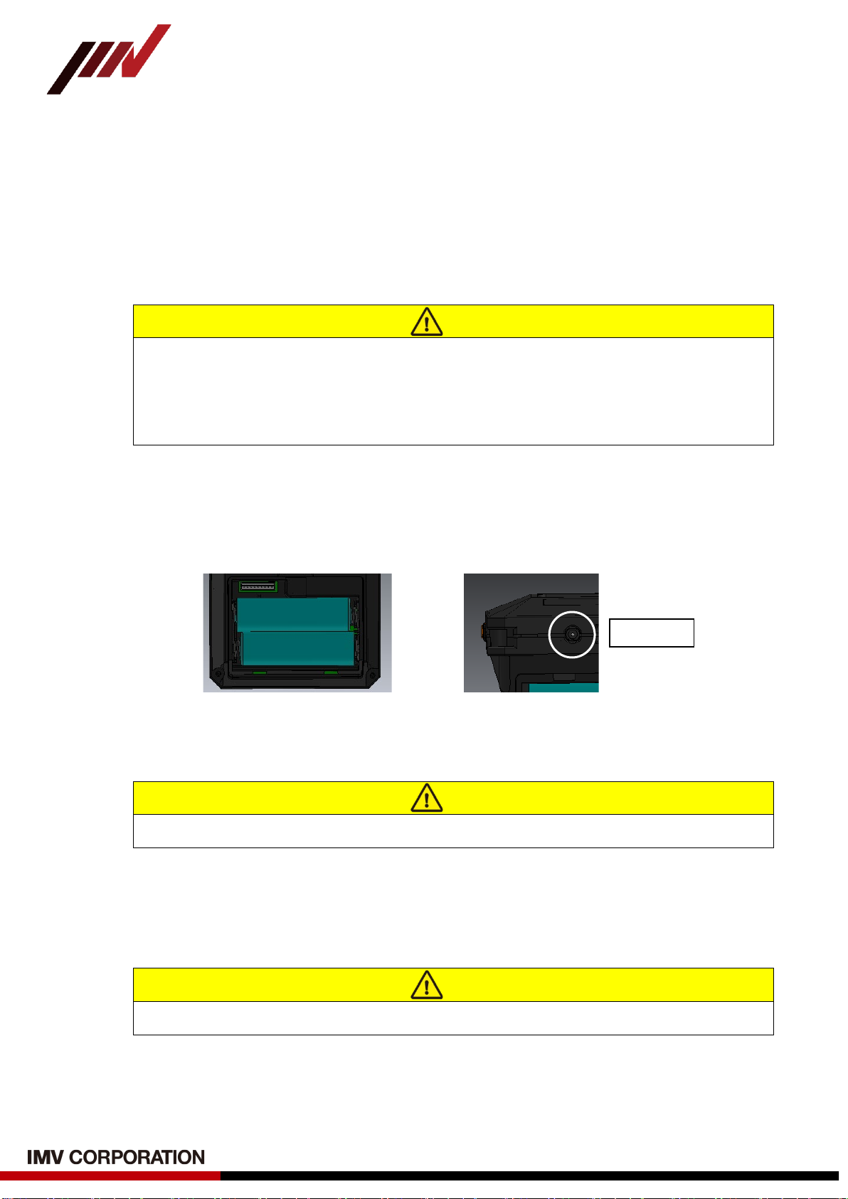
(2) Check the polarity carefully, and set two AA batteries in the battery box (Ni-Cd or
Alkaline) (Fig.3-2).
For the use with the AC adaptor, connect the AC adapter cable to the power connector
in the bottom of the device.
(a) Installing AA batteries (b) Attaching the AC adapter
Fig.3-2 Power Supply Method
Pay attention to the polarity of the battery.
(3) Connect the pickup cable to the pickup connector.
In addition, when measuring, pickup installed or fixed for object. For actual measurement,
refer to the following sections.
Refer to section 10 when fixing the pickup.
(4) Display Language Setting
VM-3024 can switch between Japanese and English as needed. Refer to section 4-6.
+
+
DC Jack
Caution
Caution
Caution
-10 -
VM-3024S/H Instruction Manual
(Compatible with Version 2.16 or later)
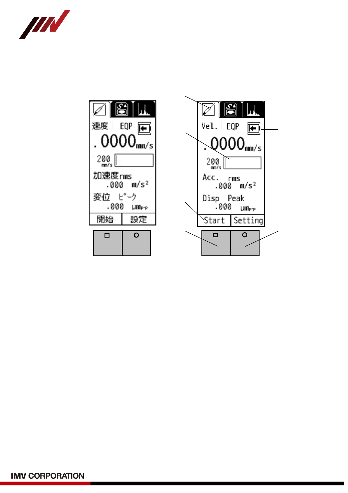
3-2. Measurement Screen
Turn on the SmartVibro by sliding an orange switch on the left side of the device, initial
screen (Fig.3-3) will appear. Operate the device by using the touch screen and two buttons.
(Japanese) (English)
Fig.3-3 Initial Screen
(1) Standard Measurement Mode
VM-3024S is equipped with this mode only.
(2) Measurement Range Bar
This shows the level of measurement data.
The data is not absolute, but rough indication.
(3) Function Indicator
Valid functions are indicated.
In Fig.3-3, “Start” and “Setting” are operative.
(4) Battery Indicator
This appears when the battery level is low.
(5) Measurement Button
In the measurement mode, you can start or hold measurement when you press this
button.
In the setting mode, you can check the battery level (refer to section 4-8).
(6) Function Button
In the measurement mode, range display will appear when you press this button.
In the FFT mode (only VM-3024H), this button would switch the display from
detailed to simple indication of the result, and vice versa (refer to section 5-1).
(1)
(2) (4)
(3)
(5) (6)

-11 -
VM-3024S/H Instruction Manual
(Compatible with Version 2.16 or later)
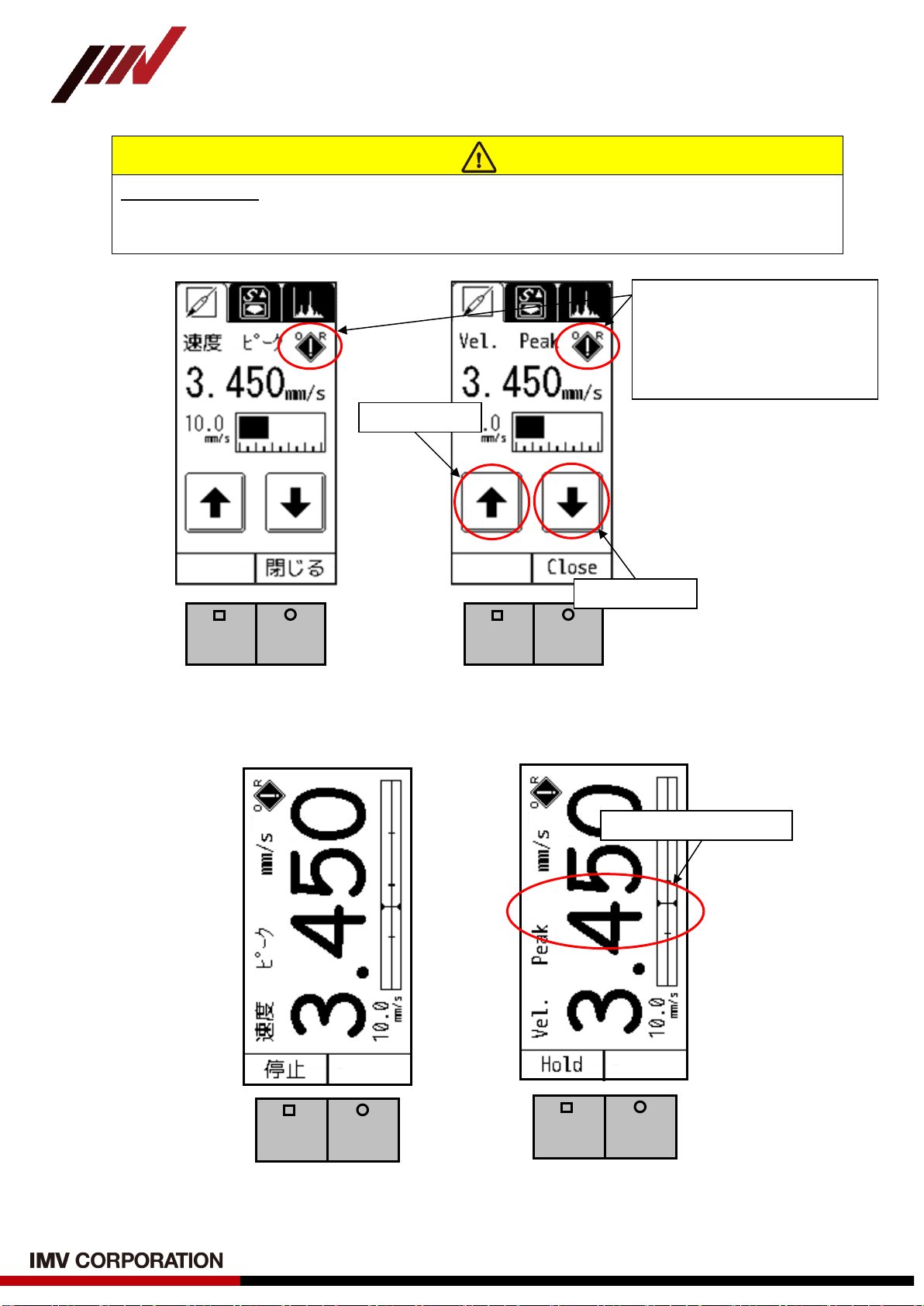
3-3. Operations during Measurement
Touching “Start” on the touch screen or press “Measurement Button” in Fig.3-3 would
start measurement. The screen displays measurement status (Fig.3-4).
Once you touch “Hold” on the touch screen or press “Function Button” would hold
measurement and the display (AC output when stopped is not retained).
(Japanese)(English)
Fig.3-4 Display during Measurement
(1) How to change the Range
When the Auto Range function is “OFF” (refer to section 4-4.), the range key will
be activated during measurement (Fig 3-4).
Touching “Range” on the touch screen or pressing “Function Button” will show the
range setting display. You may adjust the range accordingly.
The icon will appear on the upper right corner of the screen when the value is
over the range (Fig.3-5).
(2) About Excessive Input State (Measurement Impossible State)
When is displayed on the upper right of the screen, regardless of main unit
version, input speed value exceeds the hardware range (amplifier gain), and the
waveform is distorted and unsuitableness state.
In this case, do not use it as a measurement value because it is not possible to
measure accurately.
Touch here to zoom in.
Caution
-12 -
VM-3024S/H Instruction Manual
(Compatible with Version 2.16 or later)
How to Zoom In
Touch the range bar area on the screen to zoom in the image (Fig.3-4). To zoom out,
touch the same area again (Fig.3-6).
(Japanese)(English)
Fig.3-5 Display during Changing the Range
(Japanese) (English)
Fig.3-6 Enlarged
Touch here to zoom out.
Range Up
Range Down
<Excessive Input State>
When this mark display appears,
the measured value is inaccurate.
Please measure with the mark
disappearing.
-13 -
VM-3024S/H Instruction Manual
(Compatible with Version 2.16 or later)
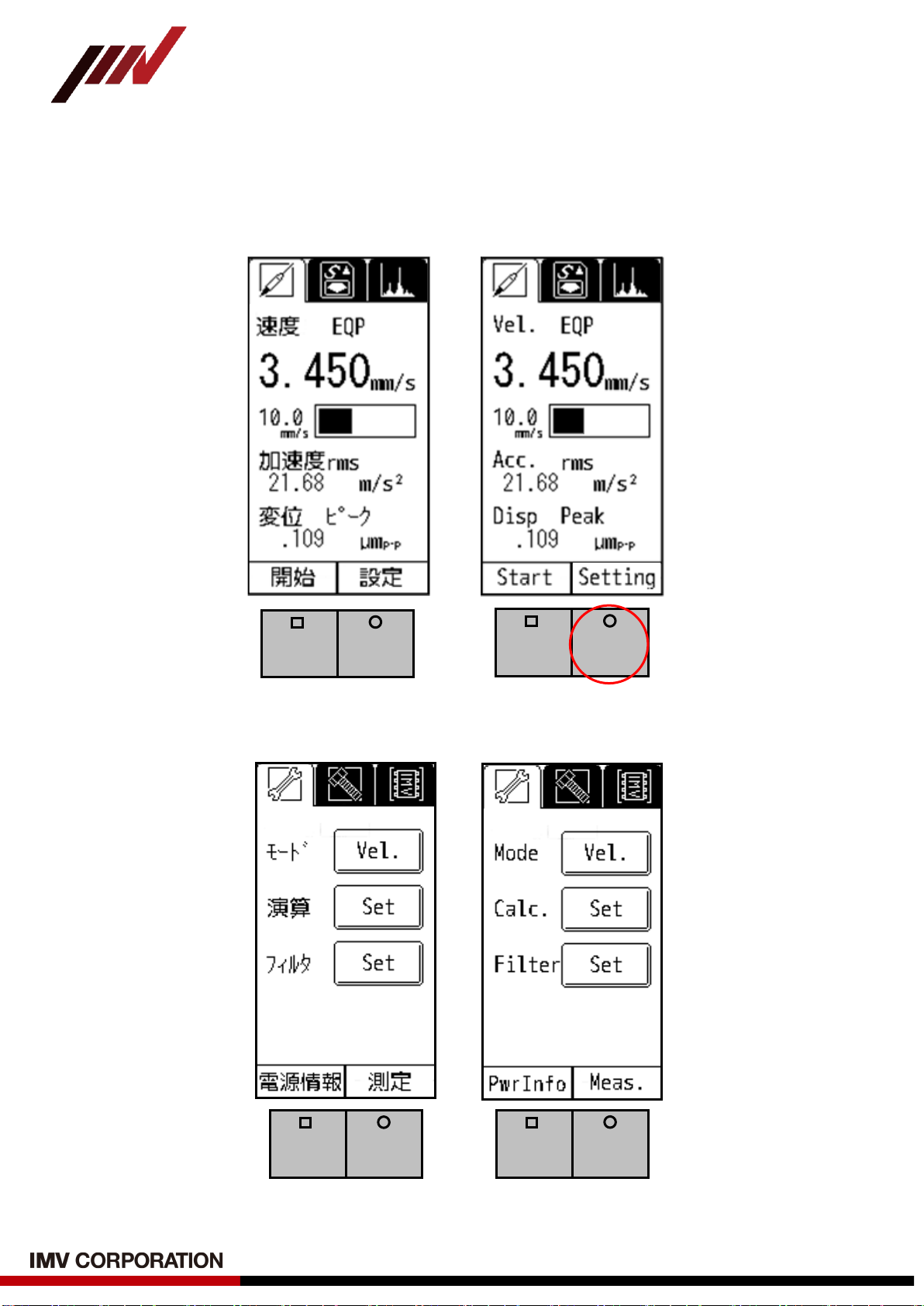
4. Setting
This section explains how to make various settings such as measurement mode.
As shown in Fig.4-1, the setting screen will appear when pressing “Function Button” or touching
"Setting" on the touch screen when “setting” is indicated in the function indicator (Fig.4-2).
(Japanese)(English)
Fig.4-1 “Setting” in the Function Indicator
(Japanese)(English)
Fig.4-2 Mode and Calculation Setting Screen

-14 -
VM-3024S/H Instruction Manual
(Compatible with Version 2.16 or later)
The setting screen can be switched by touching the icon at the top of the screen (Fig.4-3).
(Japanese) (English)
Fig.4-3 Switching the setting screen
Switching is in the following order.
Setting Icon

-15 -
VM-3024S/H Instruction Manual
(Compatible with Version 2.16 or later)
4-1. Mode Setting
When “Vel.” is selected for the Mode (Fig.4-4), the physical amount is shown at the top
of the measurement screen. Also, the enlarged screen will show the physical amount
accordingly.
(Japanese) (English)
Fig.4-4 Mode Setting
In “Mode”, the setting mode changes in the following order each time the button is
touched.
After setting mode, press “Measurement Button” button or touch "Meas." on the touch
screen, return to the measurement screen (Fig.4-5).
(Japanese) (English)
Fig.4-5 How to return to the Measurement Screen
Vel .
Acc.
Disp.
-16 -
VM-3024S/H Instruction Manual
(Compatible with Version 2.16 or later)
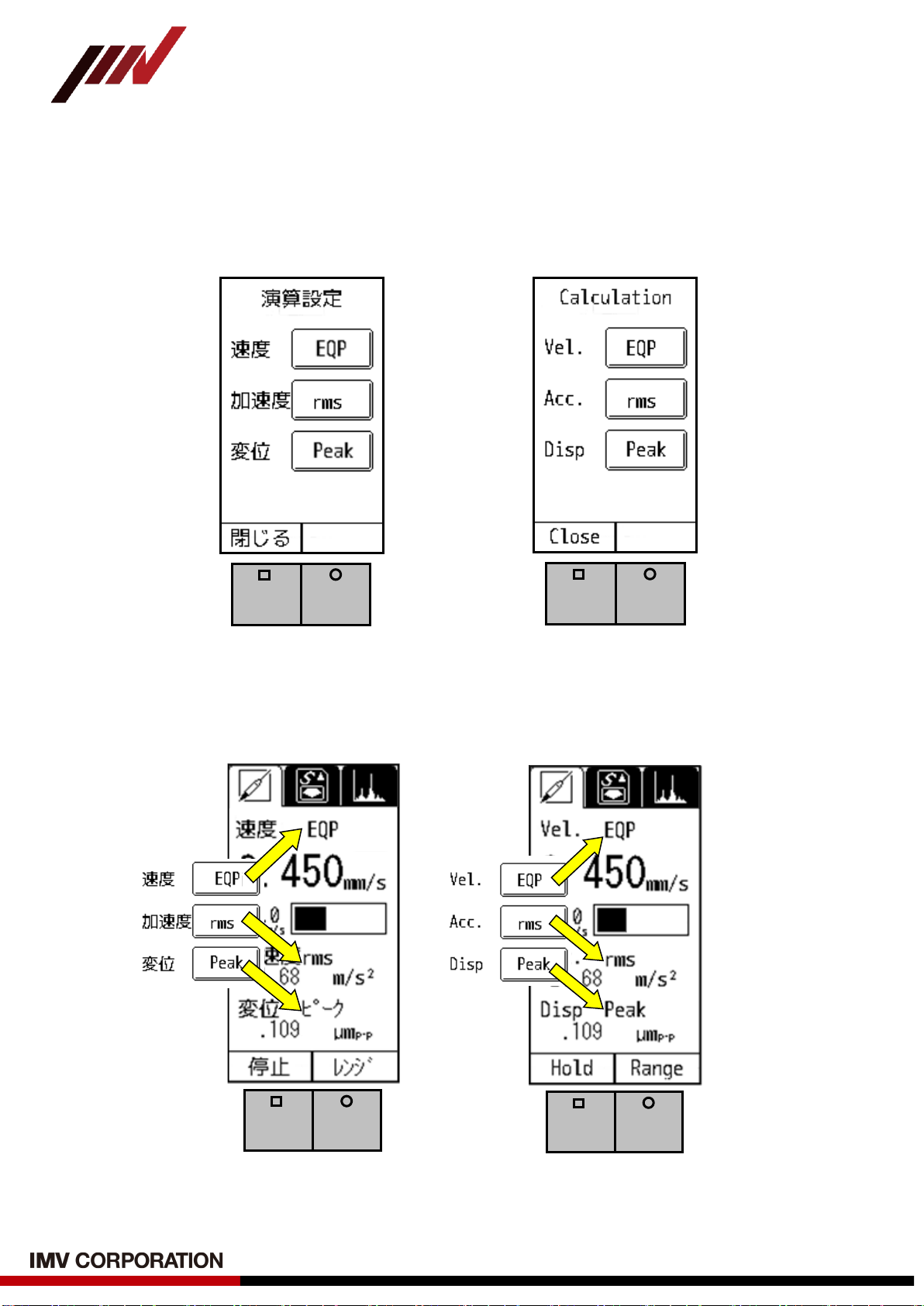
4-2. Calculation Setting
You can set how to indicate the physical amount of measurement results in calculation
setting “Calc.”.
As you touch “Set” in Fig.4-2, Fig.4-6 will appear.
(Japanese) (English)
Fig.4-6 Calculation Setting
The calculation method selected in Fig.4-6 will be displayed on the screen (Fig.4-7).
(Japanese) (English)
Fig.4-7 Example of the Setting Screen

-17 -
VM-3024S/H Instruction Manual
(Compatible with Version 2.16 or later)
Calculation settings change each time the button is touched.
Switching is in the following method.
Acc.
Vel.
Disp.
(1) A brief Description of each Calculation Method
rms: “rms” is “Root Mean Square”. This is the square root of the mean of the squares
of the time-series data gathered from measurement. ISO standard sets RMS as
evaluation criteria of the vibration velocity, which is also known as vibration
severity.
EQP: EQP is a value gained by “rms”× √2
. This formula is suitable to use for
measurement of sine vibration generated by rotational machines, for example.
Peak: The maximum value of the time-series data.
For detailed explanation, refer to the definitions in Section 10.
(2) Setting of VM-3004 and VM-3304
When had used VM-3004 and VM-3304 in past, should not use “Peak” setting, but use
the same setting as VM-3004 or VM-3304.
Recommended settings for VM-3024 are as shown in the table below.
Model
VM-3004
VM-3304
VM-3024S
VM-3024H
Acc.
rms
rms
EQP
EQP
Vel .
rms
rms
EQP
EQP
Disp.
EQP
EQP
―
Peak
rms
EQP
Peak
EQP
Peak
-18 -
VM-3024S/H Instruction Manual
(Compatible with Version 2.16 or later)
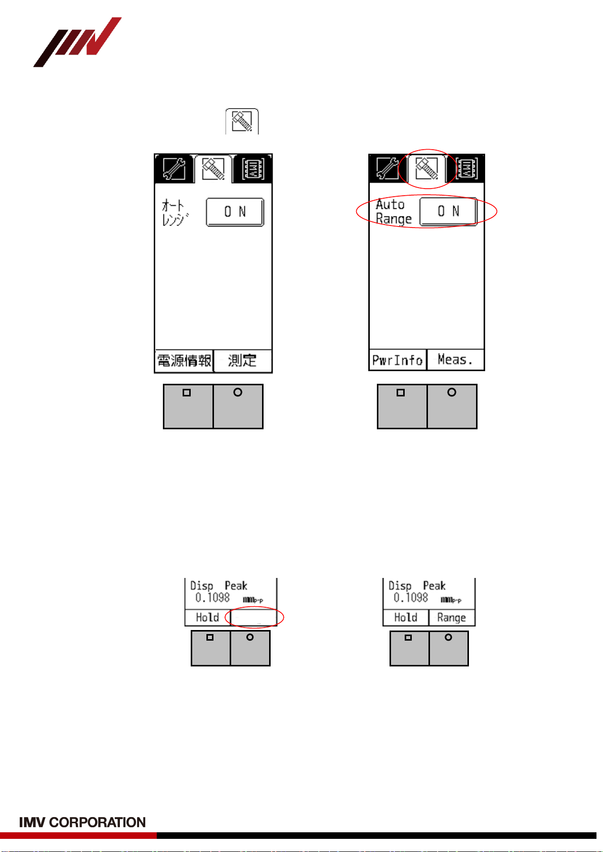
4-3. Setting of Auto Range
To set Auto Range, select tab on the setting screen (Fig.4-8).
(Japanese) (English)
Fig.4-8 Setting Page of Auto Range
When auto range is "ON", range will be adjusted automatically during measurement
(Fig.4-8). “Range” will not be indicated on the measurement display. In this case,
“Function Button” is not effective (Fig.4-9).
You can switch between “ON” and “OFF” by touching Auto Range button on the screen.
(a) Auto Range is “ON” (b) Auto Range is “OFF”
Fig.4-9 Measuring Screen of Auto Range “ON” and “OFF”
-19 -
VM-3024S/H Instruction Manual
(Compatible with Version 2.16 or later)
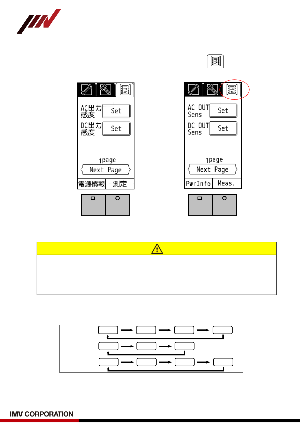
4-4. Sensitivity Setting of AC and DC Output
To set the sensitivity of AC Output and DC Output, select the tab on the setting
screen (Fig.4-10).
(Japanese) (English)
Fig.4-10 AC and DC Output Sensitivity Setting Page
Touch “Next Page” on the setting screen shown in Fig.4-12 to move to the second page.
There are 4 pages in total, and every time you touch “Next Page”, the screen is change
as follow.
“1page” →“2page” →“3page” →“4page” →“1page”→…
For the contents on “2page” and after, refer to section 4-6 and after.
The physical amount of output signal of ACOUT is equivalent to the physical amount designated
in the mode setting, and select the value by pressing the button. The value will switch as follows:
Vel .
mm/s
Acc.
m/s2
Disp.
μmo-p
Fig.4-11 AC Output Sensitivity Setting
15000
1500
150
15
450
45
4.5
75
7.5
0.75
0.075
-20 -
VM-3024S/H Instruction Manual
(Compatible with Version 2.16 or later)
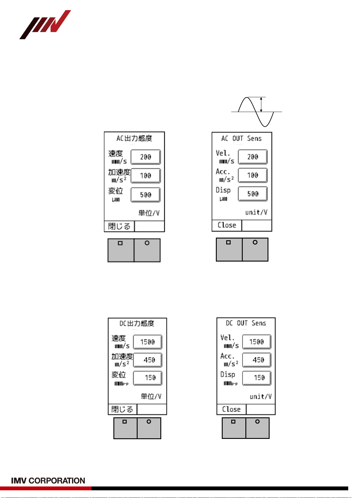
AC output sensitivity specifies the full scale for the ACOUT voltage value. Touching the
“Set” button will display Fig.4-12.
For each of velocity, acceleration, and displacement, set the value of voltage 1V.
In the example shown in Fig.4-12, the settings are as follows.
Vel.: “1V” is equivalent “200mm/s EQP”
Acc.: “1V” is equivalent “100m/s2EQP”
Disp.: “1V” is equivalent “500μmo-p”
(Japanese) (English)
Fig.4-12 AC Output Sensitivity Setting Page
On the other hand, DC output sensitivity specifies the full scale for the DCOUT voltage
value. Touching the “Set” button will display Fig.4-13.
(Japanese) (English)
Fig.4-13 DC Output Sensitivity Setting Page
1V
This manual suits for next models
1
Table of contents
Other IMV Measuring Instrument manuals


